Page 2842 of 5135
510DL±02
D30509
������
������
D30705
LHD:
A
B
RHD:
Matchmarks
Matchmarks
A
B
51±36
±
POWER STEERING RACK & PINION POWER STEERING GEAR ASSY
AVENSIS REPAIR MANUAL (RM1018E)
OVERHAUL
NOTICE:
When installing, coat the parts indicated by the arrows with power steering fluid or molybdenum dis-
ulfide lithium base grease (See page 51±34).
1. INSPECT CENTER FRONT WHEEL
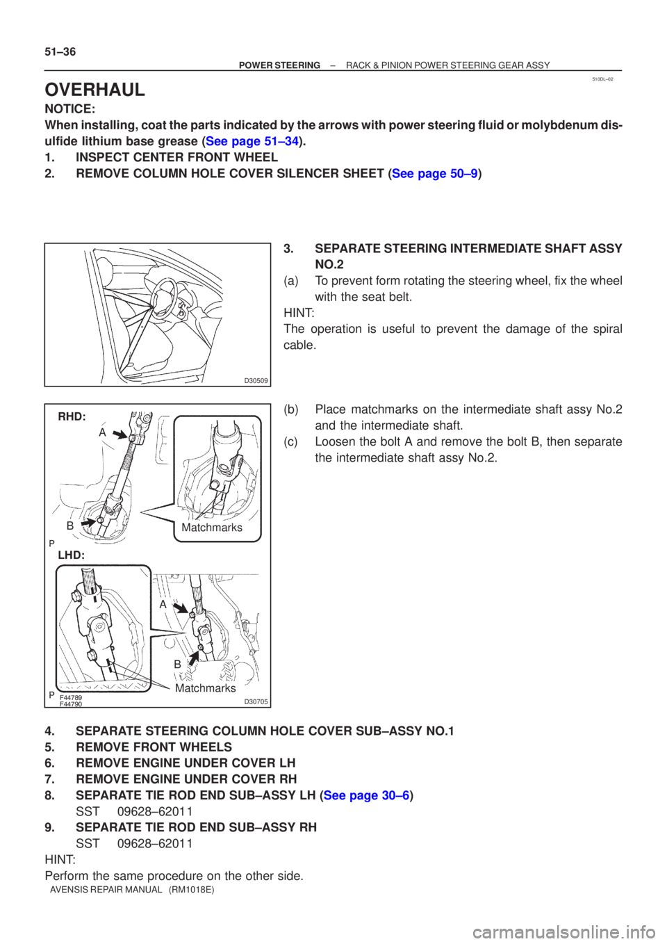
2.REMOVE COLUMN HOLE COVER SILENCER SHEET (See page 50±9) 3. SEPARATE STEERING INTERMEDIATE SHAFT ASSYNO.2
(a) To prevent form rotating the steering wheel, fix the wheel with the seat belt.
HINT:
The operation is useful to prevent the damage of the spiral
cable.
(b) Place matchmarks on the intermediate shaft assy No.2 and the intermediate shaft.
(c) Loosen the bolt A and remove the bolt B, then separate the intermediate shaft assy No.2.
4. SEPARATE STEERING COLUMN HOLE COVER SUB±ASSY NO.1
5. REMOVE FRONT WHEELS
6. REMOVE ENGINE UNDER COVER LH
7. REMOVE ENGINE UNDER COVER RH
8.SEPARATE TIE ROD END SUB±ASSY LH (See page 30±6) SST 09628±62011
9. SEPARATE TIE ROD END SUB±ASSY RH
SST 09628±62011
HINT:
Perform the same procedure on the other side.
Page 2851 of 5135
������
������D30705
LHD:
A
B
RHD:
Matchmarks
Matchmarks
A
B
±
POWER STEERING RACK & PINION POWER STEERING GEAR ASSY
51±45
AVENSIS REPAIR MANUAL (RM1018E)
50. INSTALL HEIGHT CONTROL SENSOR SUB±ASSY FR RH (W/ DISCHARGE HEAD LAMP)
(See page 65±28)
51.INSTALL TIE ROD END SUB±ASSY LH (See page 30±6)
52. INSTALL TIE ROD END SUB±ASSY RH
HINT:
Perform the same procedure on the other side.
53. INSTALL FRONT WHEELS
Torque: 103 N �m (1,050 kgf �cm, 76 ft �lbf)
54. INSTALL STEERING COLUMN HOLE COVER SUB±ASSY NO.1
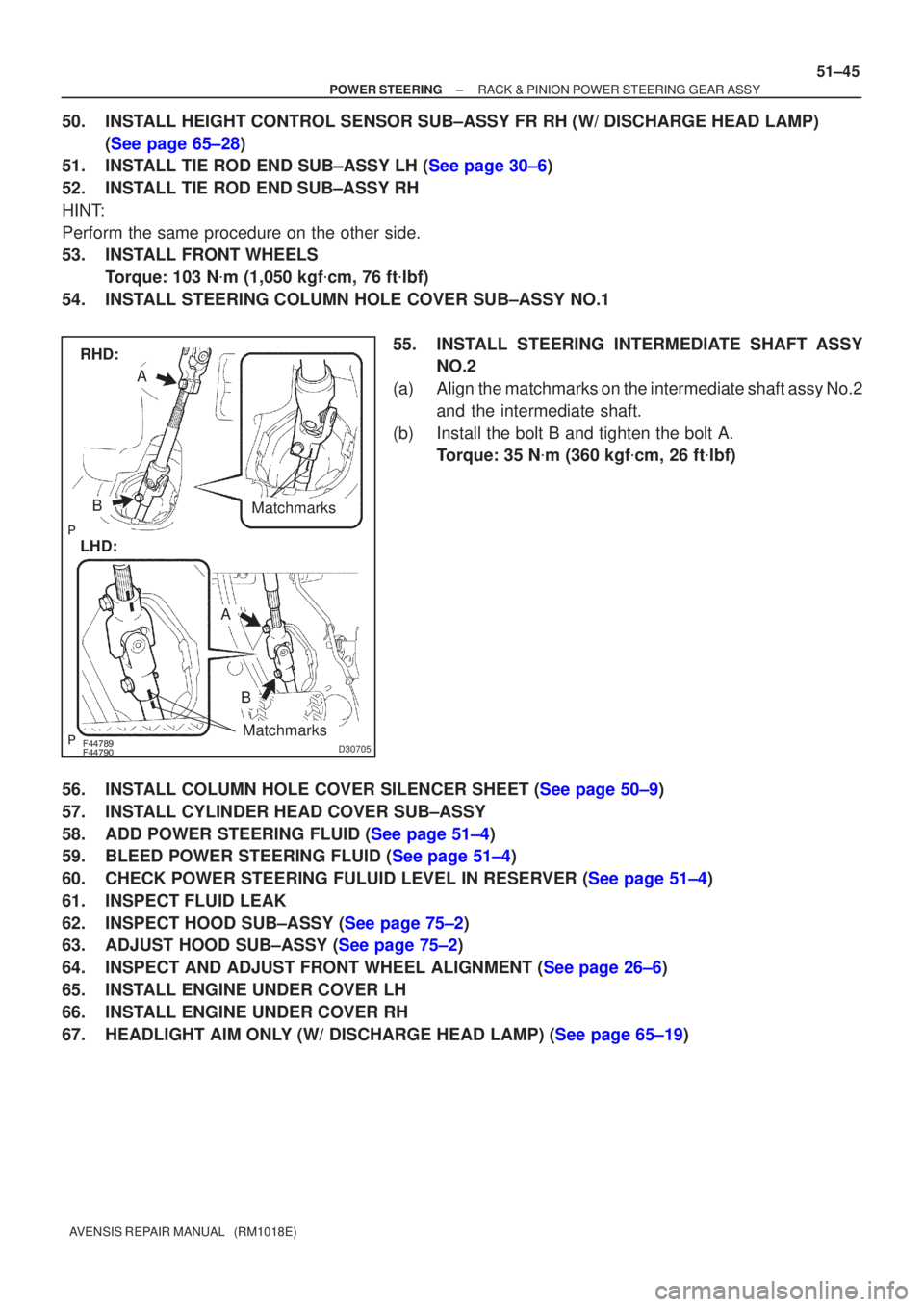
55. INSTALL STEERING INTERMEDIATE SHAFT ASSYNO.2
(a) Align the matchmarks on the intermediate shaft assy No.2 and the intermediate shaft.
(b) Install the bolt B and tighten the bolt A. Torque: 35 N �m (360 kgf �cm, 26 ft �lbf)
56.INSTALL COLUMN HOLE COVER SILENCER SHEET (See page 50±9)
57. INSTALL CYLINDER HEAD COVER SUB±ASSY
58.ADD POWER STEERING FLUID (See page 51±4)
59.BLEED POWER STEERING FLUID (See page 51±4)
60.CHECK POWER STEERING FULUID LEVEL IN RESERVER (See page 51±4)
61. INSPECT FLUID LEAK
62.INSPECT HOOD SUB±ASSY (See page 75±2)
63.ADJUST HOOD SUB±ASSY (See page 75±2)
64.INSPECT AND ADJUST FRONT WHEEL ALIGNMENT (See page 26±6)
65. INSTALL ENGINE UNDER COVER LH
66. INSTALL ENGINE UNDER COVER RH
67.HEADLIGHT AIM ONLY (W/ DISCHARGE HEAD LAMP) (See page 65±19)
Page 2854 of 5135
510DJ±02
D25320
No.1 Engine HangerNo.2 Engine Hanger
Front:Rear:
51±28
±
POWER STEERING STEERING GEAR ASSY
AVENSIS REPAIR MANUAL (RM1018E)
OVERHAUL
NOTICE:
When installing, coat the parts indicated by the arrows with power steering fluid or molybdenum dis-
ulfide lithium base grease (See page 51±27).
1. INSPECT CENTER FRONT WHEEL
2.REMOVE COLUMN HOLE COVER SILENCER SHEET (See page 50±9)
3.SEPARATE STEERING INTERMEDIATE SHAFT ASSY NO.2 (See page 51±36)
4. SEPARATE STEERING COLUMN HOLE COVER SUB±ASSY NO.1
5. REMOVE FRONT WHEELS
6. REMOVE ENGINE UNDER COVER LH
7. REMOVE ENGINE UNDER COVER RH
8.SEPARATE TIE ROD END SUB±ASSY LH (See page 30±6) SST 09628±62011
9. SEPARATE TIE ROD END SUB±ASSY RH SST 09628±62011
HINT:
Perform the same procedure on the other side.
10. REMOVE HEIGHT CONTROL SENSOR SUB±ASSY FR RH (W/ DISCHARGE HEAD LAMP)\
(See page 65±28)
11.SEPARATE FRONT STABILIZER LINK ASSY LH (See page 30±6)
12. SEPARATE FRONT STABILIZER LINK ASSY RH
HINT:
Perform the same procedure on the other side.
13.SEPARATE FRONT SUSPENSION ARM SUB±ASSY LOWER NO.1 LH (See page 30±6)
14. SEPARATE FRONT SUSPENSION ARM SUB±ASSY LOWER NO.1 RH
HINT:
Perform the same procedure on the other side.
15. REMOVE HOOD SUB±ASSY
16. REMOVE CYLINDER HEAD COVER SUB±ASSY
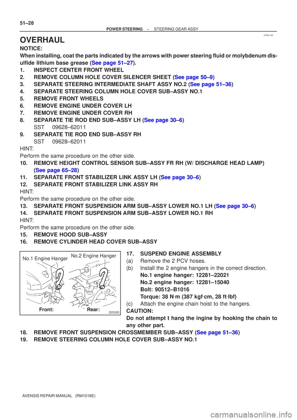
17. SUSPEND ENGINE ASSEMBLY
(a) Remove the 2 PCV hoses.
(b) Install the 2 engine hangers in the correct direction.No.1 engine hanger: 12281±22021
No.2 engine hanger: 12281±15040
Bolt: 90512±B1016
Torque: 38 N �m (387 kgf �cm, 28 ft �lbf)
(c) Attach the engine chain hoist to the hangers.
CAUTION:
Do not attempt t hang the ingine by hooking the chain to
any other part.
18.REMOVE FRONT SUSPENSION CROSSMEMBER SUB±ASSY (See page 51±36)
19. REMOVE STEERING COLUMN HOLE COVER SUB±ASSY NO.1
Page 2859 of 5135
±
POWER STEERING STEERING GEAR ASSY
51±33
AVENSIS REPAIR MANUAL (RM1018E)
46.INSTALL FRONT SUSPENSION ARM SUB±ASSY LOWER NO.1 LH (See page 30±6)
47. INSTALL FRONT SUSPENSION ARM SUB±ASSY LOWER NO.1 RH
HINT:
Perform the same procedure on the other side.
48.INSTALL FRONT STABILIZER LINK ASSY LH (See page 30±6)
49. INSTALL FRONT STABILIZER LINK ASSY RH
HINT:
Perform the same procedure on the other side.
50. INSTALL HEIGHT CONTROL SENSOR SUB±ASSY FR RH (W/ DISCHARGE HEAD LAMP)
(See page 65±28)
51.INSTALL TIE ROD END SUB±ASSY LH (See page 30±6)
52. INSTALL TIE ROD END SUB±ASSY RH
HINT:
Perform the same procedure on the other side.
53. INSTALL FRONT WHEELS Torque: 103 N �m (1,050 kgf �cm, 76 ft �lbf)
54. INSTALL STEERING COLUMN HOLE COVER SUB±ASSY NO.1
55.INSTALL STEERING INTERMEDIATE SHAFT ASSY NO.2 (See page 51±36)
56.INSTALL COLUMN HOLE COVER SILENCER SHEET (See page 50±9)
57. INSTALL CYLINDER HEAD COVER SUB±ASSY
58.INSPECT HOOD SUB±ASSY (See page 75±2)
59.ADJUST HOOD SUB±ASSY (See page 75±2)
60.INSPECT AND ADJUST FRONT WHEEL ALIGNMENT (See page 26±6)
61. INSTALL ENGINE UNDER COVER LH
62. INSTALL ENGINE UNDER COVER RH
63.HEADLIGHT AIM ONLY (W/ DISCHARGE HEAD LAMP) (See page 65±19)
Page 2870 of 5135
510DG±02
F40529
Turn
Hold
D30330
SST(s)
A
B
F40247
SST(s)
±
POWER STEERING VANE PUMP ASSY (AZ Series)
51±9
AVENSIS REPAIR MANUAL (RM1018E)
OVERHAUL
NOTICE:
�When using a vise, do not over tighten.
�When installing, coat the parts indicated by the arrows with power steer\
ing fluid
(See page 51±8).
1. REMOVE FRONT WHEEL RH
2. REMOVE ENGINE UNDER COVER RH
3. REMOVE FAN AND GENERATOR V BELT 1AZ±FE: (See page 14±105)
1AZ±FSE: (See page 14±185)
4. DISCONNECT OIL RESERVOIR TO PUMP HOSE NO.1
(a) Remove the clip and disconnect the oil reservoir to pump hose No.1.
NOTICE:
Take care not to spill fluid on the V belt.
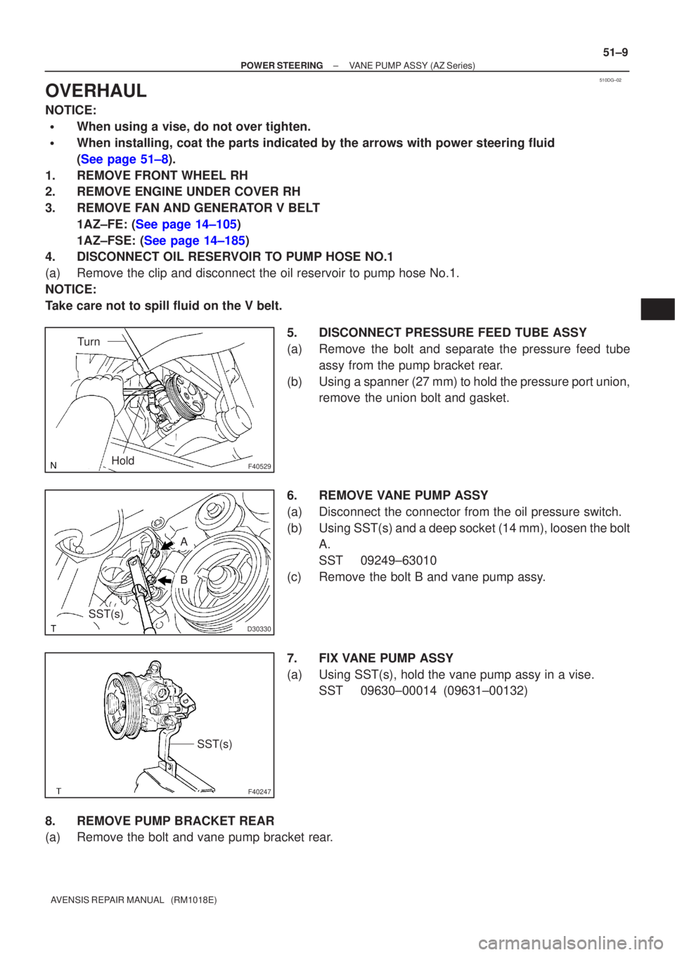
5. DISCONNECT PRESSURE FEED TUBE ASSY
(a) Remove the bolt and separate the pressure feed tubeassy from the pump bracket rear.
(b) Using a spanner (27 mm) to hold the pressure port union, remove the union bolt and gasket.
6. REMOVE VANE PUMP ASSY
(a) Disconnect the connector from the oil pressure switch.
(b) Using SST(s) and a deep socket (14 mm), loosen the bolt A.
SST 09249±63010
(c) Remove the bolt B and vane pump assy.
7. FIX VANE PUMP ASSY
(a) Using SST(s), hold the vane pump assy in a vise. SST 09630±00014 (09631±00132)
8. REMOVE PUMP BRACKET REAR
(a) Remove the bolt and vane pump bracket rear.
Page 2878 of 5135
±
POWER STEERING VANE PUMP ASSY (AZ Series)
51±17
AVENSIS REPAIR MANUAL (RM1018E)
37. CONNECT OIL RESERVOIR TO PUMP HOSE NO.1
(a) Connect the oil reservoir to pump hose No.1 with the clip.
NOTICE:
Take care not to spill fluid on the V belt.
38. INSTALL FAN AND GENERATOR V BELT
1AZ±FE: (See page 14±105)
1AZ±FSE: (See page 14±185)
39. INSTALL ENGINE UNDER COVER RH
40. INSTALL FRONT WHEEL RH Torque: 103 N �m (1,050 kgf �cm, 76 ft �lbf)
41.ADD POWER STEERING FLUID (See page 51±4)
42.BLEED POWER STEERING FLUID (See page 51±4)
43.CHECK POWER STEERING FULUID LEVEL IN RESERVER (See page 51±4)
44. INSPECT FLUID LEAK
Page 2880 of 5135
510DE±02
F40449
R11229
Normal
Abnormal
R00427
51±4
± POWER STEERINGPOWER STEERING SYSTEM
AVENSIS REPAIR MANUAL (RM1018E)
ON±VEHICLE INSPECTION
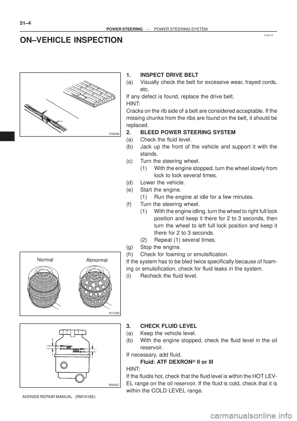
1. INSPECT DRIVE BELT
(a) Visually check the belt for excessive wear, frayed cords,
etc.
If any defect is found, replace the drive belt.
HINT:
Cracks on the rib side of a belt are considered acceptable. If the
missing chunks from the ribs are found on the belt, it should be
replaced.
2. BLEED POWER STEERING SYSTEM
(a) Check the fluid level.
(b) Jack up the front of the vehicle and support it with the
stands.
(c) Turn the steering wheel.
(1) With the engine stopped, turn the wheel slowly from
lock to lock several times.
(d) Lower the vehicle.
(e) Start the engine.
(1) Run the engine at idle for a few minutes.
(f) Turn the steering wheel.
(1) With the engine idling, turn the wheel to right full lock
position and keep it there for 2 to 3 seconds, then
turn the wheel to left full lock position and keep it
there for 2 to 3 seconds.
(2) Repeat (1) several times.
(g) Stop the engine.
(h) Check for foaming or emulsification.
If the system has to be bled twice specifically because of foam-
ing or emulsification, check for fluid leaks in the system.
(i) Recheck the fluid level.
3. CHECK FLUID LEVEL
(a) Keep the vehicle level.
(b) With the engine stopped, check the fluid level in the oil
reservoir.
If necessary, add fluid.
Fluid: ATF DEXRON� II or III
HINT:
If the fluidis hot, check that the fluid level is within the HOT LEV-
EL range on the oil reservoir. If the fluid is cold, check that it is
within the COLD LEVEL range.
Page 2881 of 5135
R11229
NormalAbnormal
R11786Engine Idling Engine Stopped5 mm (0.20 in.)
or less
±
POWER STEERING POWER STEERING SYSTEM
51±5
AVENSIS REPAIR MANUAL (RM1018E)
(c) Start the engine and run it at idle.
(d) Turn the steering wheel from lock to lock several times to
boost fluid temperature.
Fluid temperature: 80 �C (176 �F)
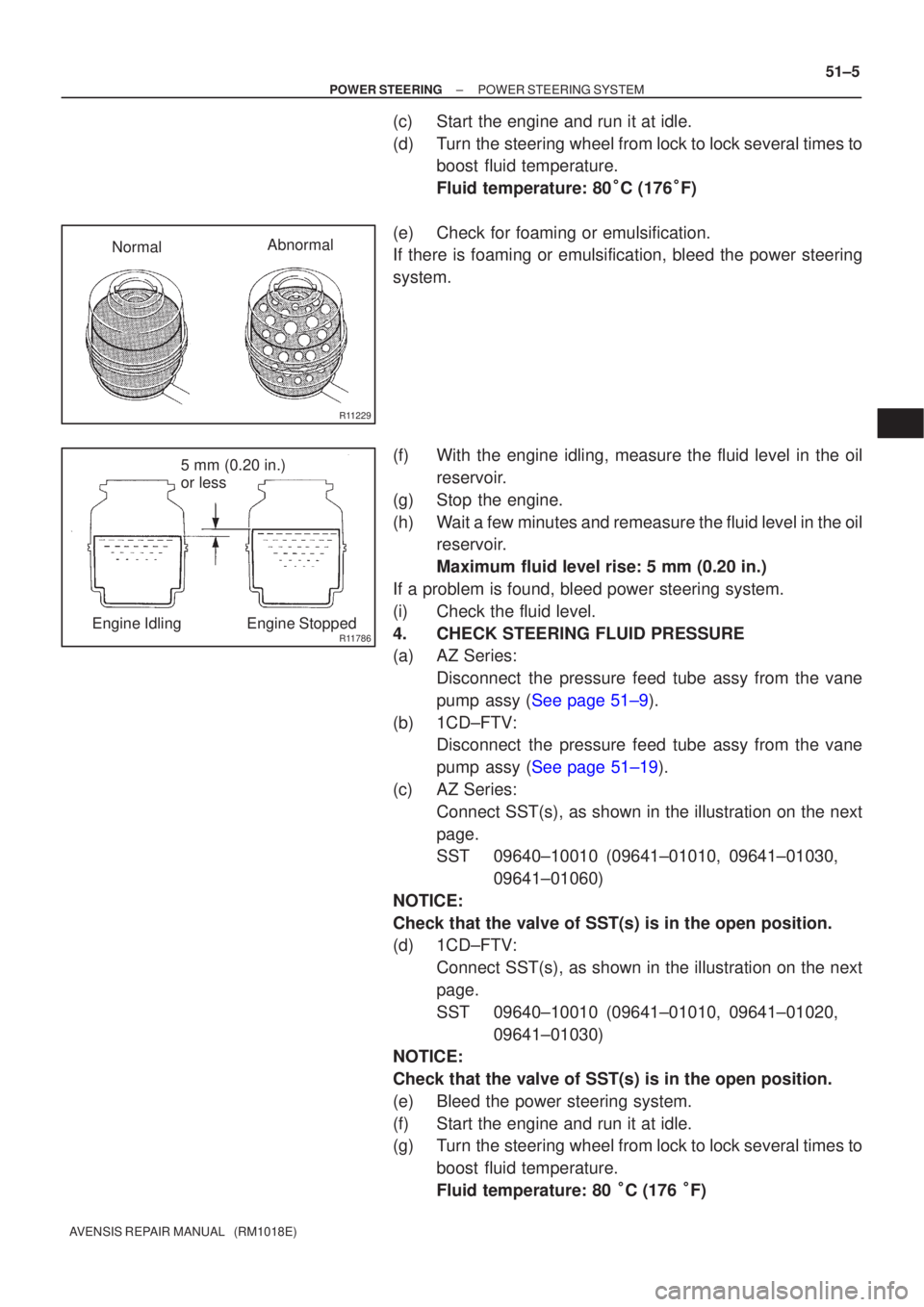
(e) Check for foaming or emulsification.
If there is foaming or emulsification, bleed the power steering
system.
(f) With the engine idling, measure the fluid level in the oil reservoir.
(g) Stop the engine.
(h) Wait a few minutes and remeasure the fluid level in the oil reservoir.
Maximum fluid level rise: 5 mm (0.20 in.)
If a problem is found, bleed power steering system.
(i) Check the fluid level.
4. CHECK STEERING FLUID PRESSURE
(a) AZ Series: Disconnect the pressure feed tube assy from the vane
pump assy (See page 51±9).
(b) 1CD±FTV: Disconnect the pressure feed tube assy from the vane
pump assy (See page 51±19).
(c) AZ Series: Connect SST(s), as shown in the illustration on the next
page.
SST 09640±10010 (09641±01010, 09641±01030, 09641±01060)
NOTICE:
Check that the valve of SST(s) is in the open position.
(d) 1CD±FTV: Connect SST(s), as shown in the illustration on the next
page.
SST 09640±10010 (09641±01010, 09641±01020, 09641±01030)
NOTICE:
Check that the valve of SST(s) is in the open position.
(e) Bleed the power steering system.
(f) Start the engine and run it at idle.
(g) Turn the steering wheel from lock to lock several times to
boost fluid temperature.
Fluid temperature: 80 �C (176 �F)