Page 2982 of 5135
600JV±01
H42615
H42616
H43001
Horn Button Contact Plate
H42618
±
SUPPLEMENTAL RESTRAINT SYSTEM SUPPLEMENTAL RESTRAINT SYSTEM
60±11
AVENSIS REPAIR MANUAL (RM1018E)
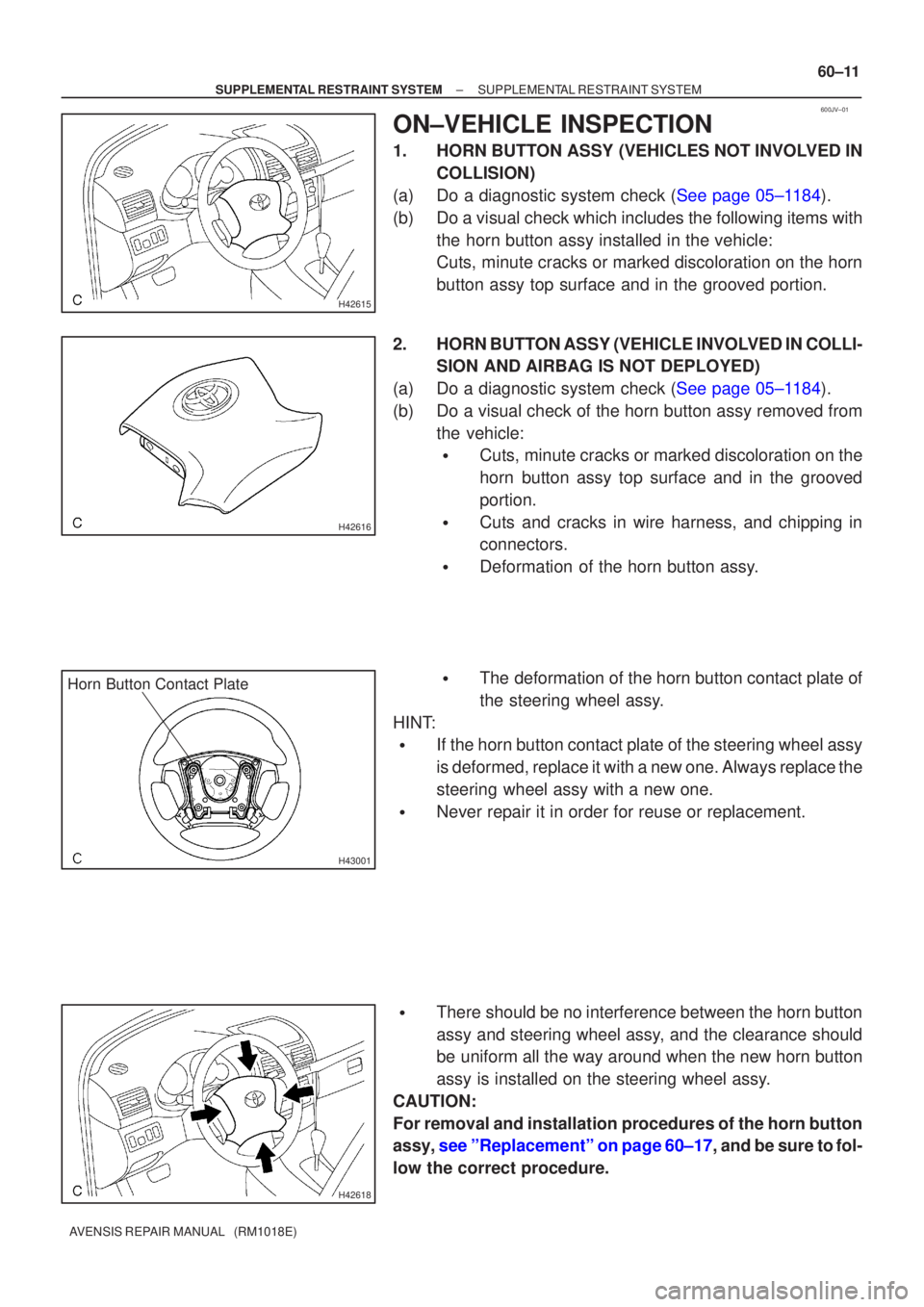
ON±VEHICLE INSPECTION
1. HORN BUTTON ASSY (VEHICLES NOT INVOLVED IN
COLLISION)
(a)Do a diagnostic system check (See page 05±1184).
(b) Do a visual check which includes the following items with the horn button assy installed in the vehicle:
Cuts, minute cracks or marked discoloration on the horn
button assy top surface and in the grooved portion.
2. HORN BUTTON ASSY (VEHICLE INVOLVED IN COLLI- SION AND AIRBAG IS NOT DEPLOYED)
(a)Do a diagnostic system check (See page 05±1184).
(b) Do a visual check of the horn button assy removed from the vehicle:
�Cuts, minute cracks or marked discoloration on the
horn button assy top surface and in the grooved
portion.
�Cuts and cracks in wire harness, and chipping in
connectors.
�Deformation of the horn button assy.
�The deformation of the horn button contact plate of
the steering wheel assy.
HINT:
�If the horn button contact plate of the steering wheel assy
is deformed, replace it with a new one. Always replace the
steering wheel assy with a new one.
�Never repair it in order for reuse or replacement.
�There should be no interference between the horn button
assy and steering wheel assy, and the clearance should
be uniform all the way around when the new horn button
assy is installed on the steering wheel assy.
CAUTION:
For removal and installation procedures of the horn button
assy, see ºReplacementº on page 60±17, and be sure to fol-
low the correct procedure.
Page 2985 of 5135
H42657
H42659
60±14
±
SUPPLEMENTAL RESTRAINT SYSTEM SUPPLEMENTAL RESTRAINT SYSTEM
AVENSIS REPAIR MANUAL (RM1018E)
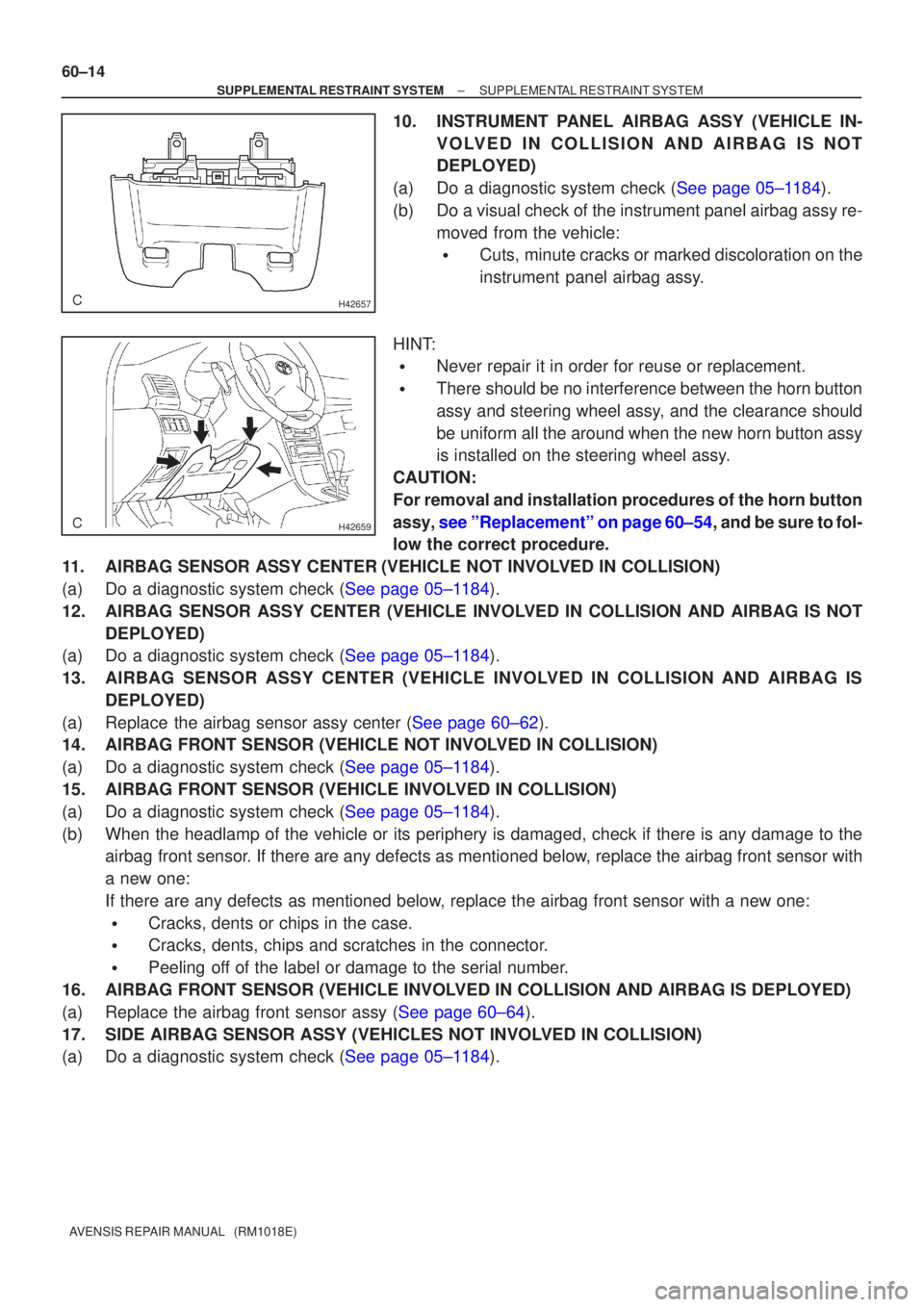
10. INSTRUMENT PANEL AIRBAG ASSY (VEHICLE IN- VOLVED IN COLLISION AND AIRBAG IS NOT
DEPLOYED)
(a)Do a diagnostic system check (See page 05±1184).
(b) Do a visual check of the instrument panel airbag assy re- moved from the vehicle:
�Cuts, minute cracks or marked discoloration on the
instrument panel airbag assy.
HINT:
�Never repair it in order for reuse or replacement.
�There should be no interference between the horn button
assy and steering wheel assy, and the clearance should
be uniform all the around when the new horn button assy
is installed on the steering wheel assy.
CAUTION:
For removal and installation procedures of the horn button
assy, see ºReplacementº on page 60±54, and be sure to fol-
low the correct procedure.
11. AIRBAG SENSOR ASSY CENTER (VEHICLE NOT INVOLVED IN COLLISION)
(a)Do a diagnostic system check (See page 05±1184).
12. AIRBAG SENSOR ASSY CENTER (VEHICLE INVOLVED IN COLLISION AND AIRBAG IS NOT DEPLOYED)
(a)Do a diagnostic system check (See page 05±1184).
13. AIRBAG SENSOR ASSY CENTER (VEHICLE INVOLVED IN COLLISION AND AIRBAG IS
DEPLOYED)
(a)Replace the airbag sensor assy center (See page 60±62).
14. AIRBAG FRONT SENSOR (VEHICLE NOT INVOLVED IN COLLISION)
(a)Do a diagnostic system check (See page 05±1184).
15. AIRBAG FRONT SENSOR (VEHICLE INVOLVED IN COLLISION)
(a)Do a diagnostic system check (See page 05±1184).
(b) When the headlamp of the vehicle or its periphery is damaged, check if t\
here is any damage to the airbag front sensor. If there are any defects as mentioned below, replace the airbag front sensor with
a new one:
If there are any defects as mentioned below, replace the airbag front sensor with a new one:
�Cracks, dents or chips in the case.
�Cracks, dents, chips and scratches in the connector.
�Peeling off of the label or damage to the serial number.
16. AIRBAG FRONT SENSOR (VEHICLE INVOLVED IN COLLISION AND AIRBAG IS DEPLOYED)
(a)Replace the airbag front sensor assy (See page 60±64).
17. SIDE AIRBAG SENSOR ASSY (VEHICLES NOT INVOLVED IN COLLISION)
(a)Do a diagnostic system check (See page 05±1184).
Page 3225 of 5135
B70029: 4 Clips
A/T Transaxle:
M/T Transaxle:
B66045Claw
±
INSTRUMENT PANEL/METER INSTRUMENT PANEL SUB±ASSY LOWER
71±15
AVENSIS REPAIR MANUAL (RM1018E)
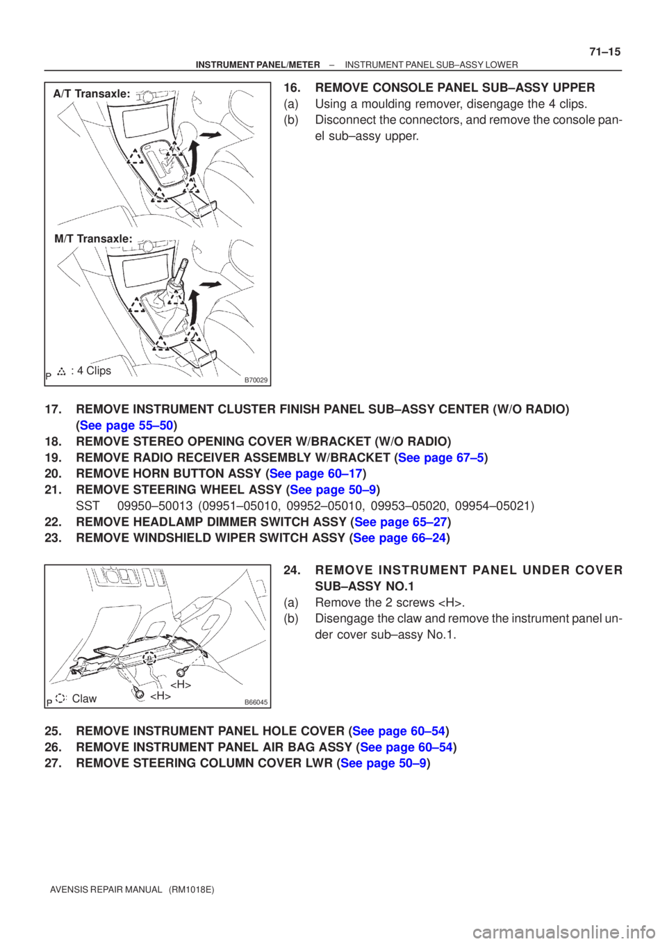
16.REMOVE CONSOLE PANEL SUB±ASSY UPPER
(a)Using a moulding remover, disengage the 4 clips.
(b)Disconnect the connectors, and remove the console pan-
el sub±assy upper.
17.REMOVE INSTRUMENT CLUSTER FINISH PANEL SUB±ASSY CENTER (W/O RADIO) (See page 55±50)
18.REMOVE STEREO OPENING COVER W/BRACKET (W/O RADIO)
19.REMOVE RADIO RECEIVER ASSEMBLY W/BRACKET (See page 67±5)
20.REMOVE HORN BUTTON ASSY (See page 60±17)
21.REMOVE STEERING WHEEL ASSY (See page 50±9) SST09950±50013 (09951±05010, 09952±05010, 09953±05020, 09954±\
05021)
22.REMOVE HEADLAMP DIMMER SWITCH ASSY (See page 65±27)
23.REMOVE WINDSHIELD WIPER SWITCH ASSY (See page 66±24)
24.REMOVE INSTRUMENT PANEL UNDER COVERSUB±ASSY NO.1
(a)Remove the 2 screws .
(b)Disengage the claw and remove the instrument panel un- der cover sub±assy No.1.
25.REMOVE INSTRUMENT PANEL HOLE COVER (See page 60±54)
26.REMOVE INSTRUMENT PANEL AIR BAG ASSY (See page 60±54)
27.REMOVE STEERING COLUMN COVER LWR (See page 50±9)
Page 3230 of 5135
71±20
±
INSTRUMENT PANEL/METER INSTRUMENT PANEL SUB±ASSY LOWER
AVENSIS REPAIR MANUAL (RM1018E)
46.ADJUST SPIRAL CABLE SUB±ASSY (See page 60±26)
47.INSTALL STEERING WHEEL ASSY (See page 50±9)
48.INSTALL HORN BUTTON ASSY (See page 60±17)
49.INSPECT HORN BUTTON ASSY (See page 60±11)
50.INSPECT SRS WARNING LIGHT (See page 05±1184)
Page 3233 of 5135
B66038
Heater to Register Duct No.2
Instrument Panel Lower Assy
Cowl Side Trim
Board RH
Front Door
Scuff Plate
RH
Floor Shift
Shift Lever
Knob Sub±assy Console Panel
Sub±assy Upper
Console Panel Sub±assy Lower
Console Box Assy RR Front Door
Scuff Plate LHCowl Side Trim
Board LH
Instrument Panel Airbag Assy
Console Rear End
Panel
Radio Receiver
Assembly w/ Bracket
Windshield
Wiper Switch Assy
Instrument Panel
Hole CoverHead lamp
Dimmer Switch Assy
Instrument Panel Under
Cover Sub±assy No.2
Horn Button Assy Steering Wheel Assy
Instrument Panel Under Cover
Sub±assy No.1
H
N´m (kgf´cm, ft´lbf) : Specified torqueM/T Transaxle: A/T Transaxle:
A/T Only:
M/T Only:
50 (510, 37)
8.8 (90, 78 in.´lbf)
orEF
D
B
Bor
EF
I
or
EF
or
EF
H
HH
H
H
HH
H
H
CC
CC
H
HConsole Panel
Sub±assy Upper
18 (184, 13)
18 (184, 13)
71±8
± INSTRUMENT PANEL/METERINSTRUMENT PANEL/METER
AVENSIS REPAIR MANUAL (RM1018E)
Page 3463 of 5135
01±8
± INTRODUCTIONTERMS
1AZ±FSE ENGINE REPAIR MANUAL (RM1019E)Abbreviations Meaning
DFLDeflector
DIFF.Differential
DIFF. LOCKDifferential Lock
D/INJDirect Injection
DLCData Link Connector
DLIDistributorless Ignition
DOHCDouble Overhead Camshaft
DPDash Pot
DSDead Soak
DSPDigital Signal Processor
DTCDiagnostic Trouble Code
DVDDigital Versatile Disc
EBDElectric Brake Force Distribution
ECAMEngine Control And Measurement System
ECDElectronic Controlled Diesel
ECDYEddy Current Dynamometer
ECTElectronic Control Transmission
ECUElectronic Control Unit
EDElectro±Deposited Coating
EDUElectronic Driving Unit
EDICElectric Diesel Injection Control
EFIElectronic Fuel Injection
E/GEngine
EGRExhaust Gas Recirculation
EGR±VMEGR±Vacuum Modulator
ELREmergency Locking Retractor
EMPSElectric Motor Power Steering
ENGEngine
ESAElectronic Spark Advance
ETCS±iElectronic Throttle Control System±intelligent
EVAPEvaporative Emission Control
EVPEvaporator
E±VRVElectric Vacuum Regulating Valve
EXExhaust
FEFuel Economy
FFFront±Engine Front±Wheel±Drive
F/GFuel Gauge
FIPGFormed In Place Gasket
FLFusible Link
F/PFuel Pump
FPUFuel Pressure Up
FrFront
F/WFlywheel
FW/DFlywheel Damper
FWDFront±Wheel±Drive
GASGasoline
GNDGround
GPSGlobal Positioning System
HACHigh Altitude Compensator
H/BHatchback
H±FUSEHigh Current Fuse
Page 3465 of 5135
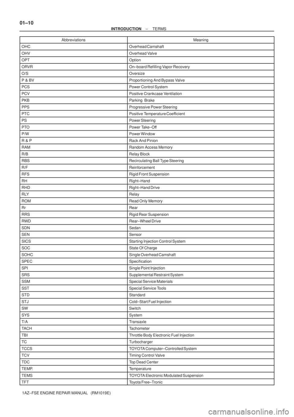
01±10
± INTRODUCTIONTERMS
1AZ±FSE ENGINE REPAIR MANUAL (RM1019E)Abbreviations Meaning
OHCOverhead Camshaft
OHVOverhead Valve
OPTOption
ORVROn±board Refilling Vapor Recovery
O/SOversize
P & BVProportioning And Bypass Valve
PCSPower Control System
PCVPositive Crankcase Ventilation
PKBParking Brake
PPSProgressive Power Steering
PTCPositive Temperature Coefficient
PSPower Steering
PTOPower Take±Off
P/WPower Window
R & PRack And Pinion
RAMRandom Access Memory
R/BRelay Block
RBSRecirculating Ball Type Steering
R/FReinforcement
RFSRigid Front Suspension
RHRight±Hand
RHDRight±Hand Drive
RLYRelay
ROMRead Only Memory
RrRear
RRSRigid Rear Suspension
RWDRear±Wheel Drive
SDNSedan
SENSensor
SICSStarting Injection Control System
SOCState Of Charge
SOHCSingle Overhead Camshaft
SPECSpecification
SPISingle Point Injection
SRSSupplemental Restraint System
SSMSpecial Service Materials
SSTSpecial Service Tools
STDStandard
STJCold±Start Fuel Injection
SWSwitch
SYSSystem
T/ATransaxle
TACHTachometer
TBIThrottle Body Electronic Fuel Injection
TCTurbocharger
TCCSTOYOTA Computer±Controlled System
TCVTiming Control Valve
TDCTop Dead Center
TEMP.Temperature
TEMSTOYOTA Electronic Modulated Suspension
TFTToyota Free±Tronic
Page 3466 of 5135
± INTRODUCTIONTERMS
01±11
1AZ±FSE ENGINE REPAIR MANUAL (RM1019E)Abbreviations Meaning
TISTotal Information System For Vehicle Development
T/MTransmission
TMCTOYOTA Motor Corporation
TMMKTOYOTA Motor Manufacturing Kentucky, Inc.
TRCTraction Control System
TURBOTurbocharge
TWCThree±Way Catalyst
U/DUnderdrive
U/SUndersize
VCVVacuum Control Valve
VENTVentilator
VINVehicle Identification Number
VPSVariable Power Steering
VSCVehicle Stability Control
VSVVacuum Switching Valve
VTVVacuum Transmitting Valve
VVT±iVariable Valve Timing±intelligent
w/With
WGNWagon
W/HWire Harness
w/oWithout
WU±TWCWarm Up Three±way Catalytic Converter
WU±OCWarm Up Oxidation Catalytic Converter
1stFirst
2ndSecond
2WDTwo Wheel Drive Vehicle (4 x 2)
3rdThird
4thFourth
4WDFour Wheel Drive Vehicle (4 x 4)
4WSFour Wheel Steering System
5thFifth