Page 2524 of 5135
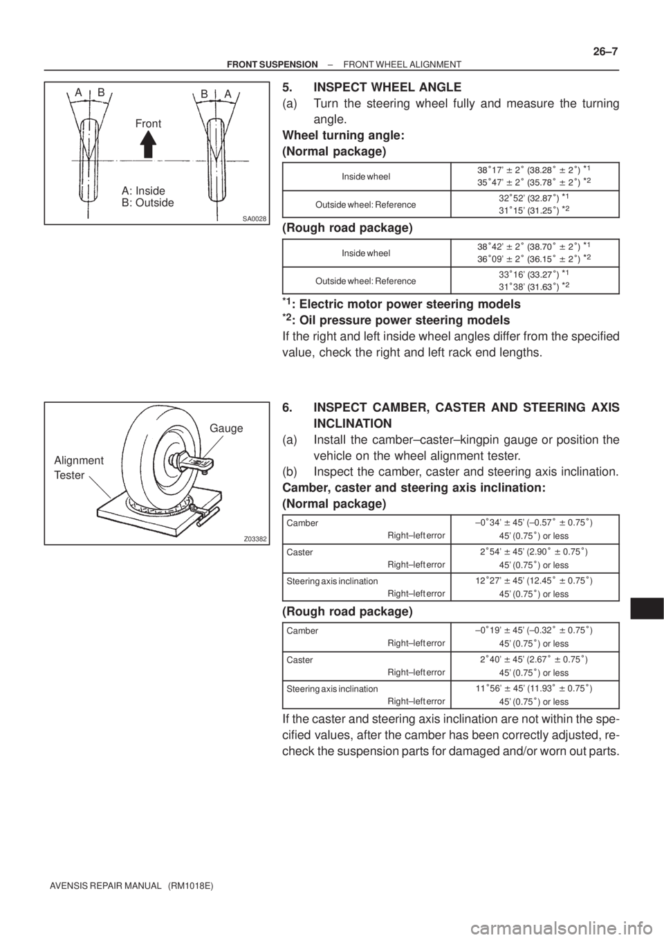
SA0028
AB
FrontA B
A: Inside
B: Outside
Z03382
Alignment
TesterGauge
± FRONT SUSPENSIONFRONT WHEEL ALIGNMENT
26±7
AVENSIS REPAIR MANUAL (RM1018E)
5. INSPECT WHEEL ANGLE
(a) Turn the steering wheel fully and measure the turning
angle.
Wheel turning angle:
(Normal package)
Inside wheel
�17' � 2� �
��
� � �����
�47' � 2� �
��
� � �����
Outside wheel: Reference32�52' � ��
�����
31��5' � ���
����
(Rough road package)
Inside wheel
�42' � 2� �
���� � �����
��09' � 2� � ���
� � �����
Outside wheel: Reference33�16' � �������
31�38' � ��� ����
*1: Electric motor power steering models
*2: Oil pressure power steering models
If the right and left inside wheel angles differ from the specified
value, check the right and left rack end lengths.
6. INSPECT CAMBER, CASTER AND STEERING AXIS
INCLINATION
(a) Install the camber±caster±kingpin gauge or position the
vehicle on the wheel alignment tester.
(b) Inspect the camber, caster and steering axis inclination.
Camber, caster and steering axis inclination:
(Normal package)
Camber
Right±left error±0�34' � 45' (±0.57� � 0.75�)
45' (0.75�) or less
Caster
Right±left error��54' � 45' (2.90� � 0.75�)
45' (0.75�) or less
Steering axis inclination
Right±left error���27' � 45' (12.45� � 0.75�)
45' (0.75�) or less
(Rough road package)
Camber
Right±left error±0�19' � 45' (±0.32� � 0.75�)
45' (0.75�) or less
Caster
Right±left error��40' � 45' (2.67� � 0.75�)
45' (0.75�) or less
Steering axis inclination
Right±left error���56' � 45' (11.93� � 0.75�)
45' (0.75�) or less
If the caster and steering axis inclination are not within the spe-
cified values, after the camber has been correctly adjusted, re-
check the suspension parts for damaged and/or worn out parts.
Page 2525 of 5135
F13683
26±8
± FRONT SUSPENSIONFRONT WHEEL ALIGNMENT
AVENSIS REPAIR MANUAL (RM1018E)
7. ADJUST CAMBER
NOTICE:
After the camber has been adjusted, inspect the toe±in.
(a) Remove the front wheel.
(b) Remove the 2 bolts and nuts on the lower side of the
shock absorber.
If reusing the bolts and/or nuts, coat the threads of nuts with en-
gine oil.
(c) Clean the installation surfaces of the shock absorber and
the steering knuckle.
(d) Temporarily install the 2 bolts and nuts.
Page 2528 of 5135
300JY±01
������F45751
SST
C80291
F44775
C67088
30±22
±
DRIVE SHAFT / PROPELLER SHAFT FRONT AXLE HUB SUB±ASSY LH
AVENSIS REPAIR MANUAL (RM1018E)
REPLACEMENT
HINT:
Replace the RH side by the same procedures as the LH side.
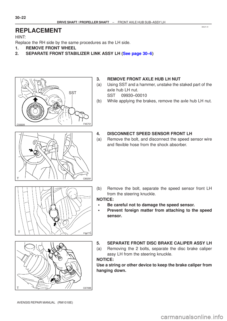
1. REMOVE FRONT WHEEL
2.SEPARATE FRONT STABILIZER LINK ASSY LH (See page 30±6) 3. REMOVE FRONT AXLE HUB LH NUT
(a) Using SST and a hammer, unstake the staked part of theaxle hub LH nut.
SST 09930±00010
(b) While applying the brakes, remove the axle hub LH nut.
4. DISCONNECT SPEED SENSOR FRONT LH
(a) Remove the bolt, and disconnect the speed sensor wire and flexible hose from the shock absorber.
(b) Remove the bolt, separate the speed sensor front LH from the steering knuckle.
NOTICE:
�Be careful not to damage the speed sensor.
�Prevent foreign matter from attaching to the speed
sensor.
5. SEPARATE FRONT DISC BRAKE CALIPER ASSY LH
(a) Removing the 2 bolts, separate the disc brake caliper assy LH from the steering knuckle.
NOTICE:
Use a string or other device to keep the brake caliper from
hanging down.
Page 2670 of 5135
320G5±02
F45426
F45427
F42642
±
BRAKE STEERING SENSOR
32±65
AVENSIS REPAIR MANUAL (RM1018E)
STEERING SENSOR
REPLACEMENT
1.PRECAUTION (See page 60±1)
2. REMOVE PLACE FRONT WHEELS FACING STRAIGHT AHEAD
3.DISCONNECT BATTERY NEGATIVE TERMINAL (See page 60±1)
4.REMOVE HORN BUTTON ASSY (See page 60±17)
5.REMOVE STEERING WHEEL ASSY (See page 50±9)
6.REMOVE STEERING COLUMN COVER LWR (See page 50±9)
7. REMOVE STEERING COLUMN COVER W/INSTRUMENT CLUSTER FINISH PANEL ASSY
(See page 50±9)
8.REMOVE STEERING COLUMN ASSY(See page 50±9)
9.REMOVE STEERING INTERMEDIATE SHAFT ASSY NO.2 (See page 50±9)
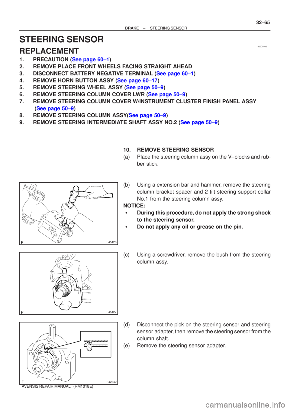
10. REMOVE STEERING SENSOR
(a) Place the steering column assy on the V±blocks and rub-ber stick.
(b) Using a extension bar and hammer, remove the steering column bracket spacer and 2 tilt steering support collar
No.1 from the steering column assy.
NOTICE:
�During this procedure, do not apply the strong shock
to the steering sensor.
�Do not apply any oil or grease on the pin.
(c) Using a screwdriver, remove the bush from the steering column assy.
(d) Disconnect the pick on the steering sensor and steering sensor adapter, then remove the steering sensor from the
column shaft.
(e) Remove the steering sensor adapter.
Page 2671 of 5135
F42641
F42642
F45427
F45426
32±66
±
BRAKE STEERING SENSOR
AVENSIS REPAIR MANUAL (RM1018E)
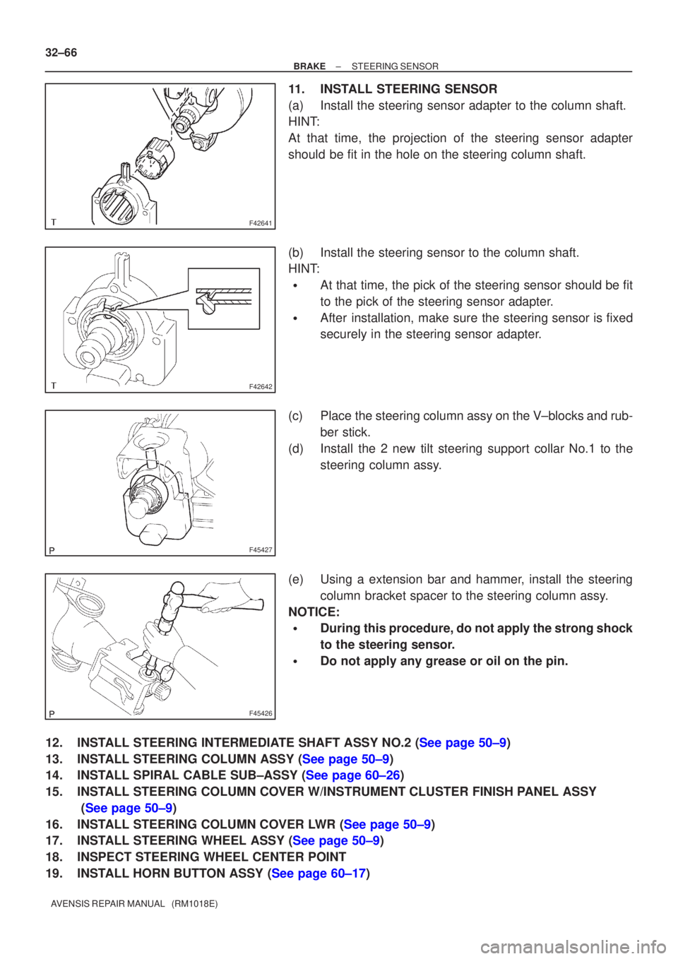
11. INSTALL STEERING SENSOR
(a) Install the steering sensor adapter to the column shaft.
HINT:
At that time, the projection of the steering sensor adapter
should be fit in the hole on the steering column shaft.
(b) Install the steering sensor to the column shaft.
HINT:
�At that time, the pick of the steering sensor should be fit
to the pick of the steering sensor adapter.
�After installation, make sure the steering sensor is fixed
securely in the steering sensor adapter.
(c) Place the steering column assy on the V±blocks and rub- ber stick.
(d) Install the 2 new tilt steering support collar No.1 to the steering column assy.
(e) Using a extension bar and hammer, install the steering column bracket spacer to the steering column assy.
NOTICE:
�During this procedure, do not apply the strong shock
to the steering sensor.
�Do not apply any grease or oil on the pin.
12.INSTALL STEERING INTERMEDIATE SHAFT ASSY NO.2 (See page 50±9)
13.INSTALL STEERING COLUMN ASSY (See page 50±9)
14.INSTALL SPIRAL CABLE SUB±ASSY (See page 60±26)
15. INSTALL STEERING COLUMN COVER W/INSTRUMENT CLUSTER FINISH PANEL ASSY (See page 50±9)
16.INSTALL STEERING COLUMN COVER LWR (See page 50±9)
17.INSTALL STEERING WHEEL ASSY (See page 50±9)
18. INSPECT STEERING WHEEL CENTER POINT
19.INSTALL HORN BUTTON ASSY (See page 60±17)
Page 2739 of 5135
±
AUTOMATIC TRANSMISSION / TRANS TRANSMISSION CONTROL CABLE ASSY
40±73
AVENSIS REPAIR MANUAL (RM1018E)
7. INSTALL INSTRUMENT PANEL SUB±ASSY UPPER W/INSTR PNL PASS L/DOOR AIR BAG ASSY
(See page 71±11)
8.ADJUST SPIRAL CABLE SUB±ASSY (See page 60±26)
9.INSTALL STEERING WHEEL ASSY (See page 50±9)
10.INSTALL HORN BUTTON ASSY (See page 60±17)
11.INSTALL EXHAUST PIPE ASSY FRONT (1ZZ±FE ENGINE TYPE) (See page 15±2)
12.INSTALL EXHAUST PIPE ASSY FRONT (1AZ±FE/1AZ±FSE ENGINE TYPE) (See page 15±7)
13.INSPECT HORN BUTTON ASSY (See page 60±17)
14.INSPECT SRS WARNING LIGHT (See page 05±1184)
15. CHECK FOR EXHAUST GAS LEAKS
16.ADJUST SHIFT LEVER POSITION (See page 40±69)
17.INSPECT SHIFT LEVER POSITION (See page 40±69)
18.CHARGE REFRIGERANT (See page 55±38)
SST 07110±58060 (07117±58060, 07117±58070, 07117±58080, 07117±58090, 07117±78050, 07117±88060, 07117±88070, 07117±88080)
19.INSPECT LEAKAGE OF REFRIGERANT (See page 55±38)
Page 2770 of 5135
410DY±01
D26902
D26903
±
MANUAL TRANSMISSION/TRANSAXLE MANUAL TRANSAXLE ASSY (1CD±FTV)
41±33
AVENSIS REPAIR MANUAL (RM1018E)
REPLACEMENT
1. INSPECT CENTER FRONT WHEEL
2.REMOVE COLUMN HOLE COVER SILENCER SHEET (See page 50±9)
3.SEPARATE STEERING INTERMEDIATE SHAFT ASSY NO.2 (See page 50±9)
4.REMOVE STEERING COLUMN HOLE COVER SUB±ASSY NO.1 (See page 50±9)
5.REMOVE STEERING INTERMEDIATE SHAFT (See page 50±9)
6. REMOVE FRONT WHEELS
7. REMOVE ENGINE UNDER COVER RH
8. REMOVE ENGINE UNDER COVER LH
9. DRAIN TRANSAXLE OIL
Torque: 49 N �m (500 kgf �cm, 36 ft �lbf)
10. REMOVE HOOD SUB±ASSY
11. REMOVE RADIATOR SUPPORT OPENING COVER
12. REMOVE ENGINE ROOM COVER SIDE
13. REMOVE ENGINE COVER NO.1
14. REMOVE AIR CLEANER ASSY
15. REMOVE BATTERY CLAMP SUB±ASSY
16. REMOVE BATTERY
17. REMOVE BATTERY TRAY
18.REMOVE AIR TUBE NO.1 (See page 14±286)
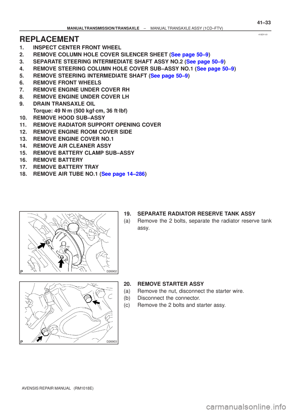
19. SEPARATE RADIATOR RESERVE TANK ASSY
(a) Remove the 2 bolts, separate the radiator reserve tankassy.
20. REMOVE STARTER ASSY
(a) Remove the nut, disconnect the starter wire.
(b) Disconnect the connector.
(c) Remove the 2 bolts and starter assy.
Page 2776 of 5135
D30815
(b)(a)
D26903
D26902
±
MANUAL TRANSMISSION/TRANSAXLE MANUAL TRANSAXLE ASSY (1CD±FTV)
41±39
AVENSIS REPAIR MANUAL (RM1018E)
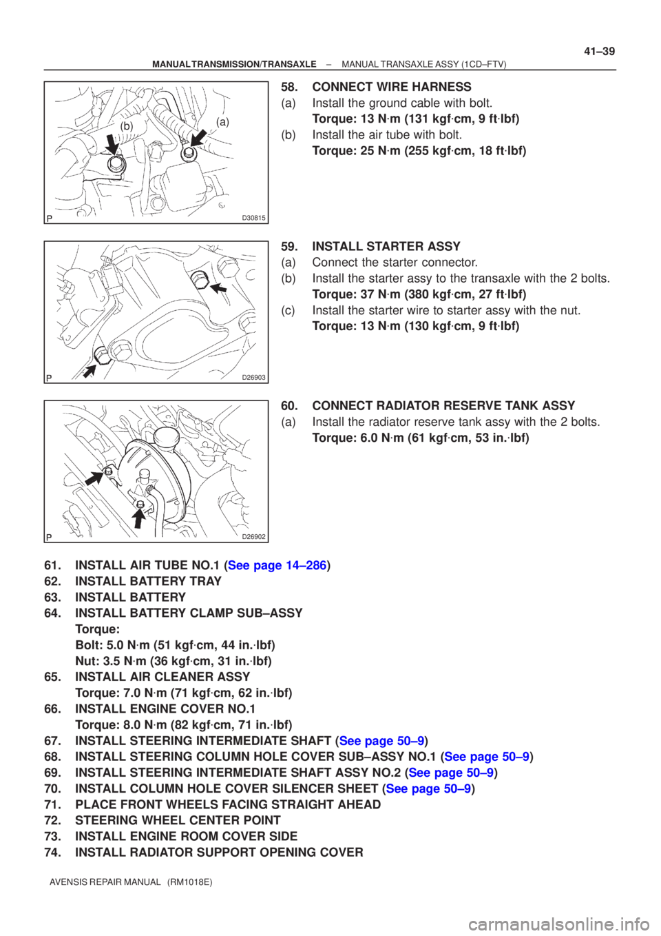
58. CONNECT WIRE HARNESS
(a) Install the ground cable with bolt.
Torque: 13 N �m (131 kgf �cm, 9 ft �lbf)
(b) Install the air tube with bolt. Torque: 25 N �m (255 kgf �cm, 18 ft �lbf)
59. INSTALL STARTER ASSY
(a) Connect the starter connector.
(b) Install the starter assy to the transaxle with the 2 bolts. Torque: 37 N �m (380 kgf �cm, 27 ft �lbf)
(c) Install the starter wire to starter assy with the nut. Torque: 13 N �m (130 kgf �cm, 9 ft �lbf)
60. CONNECT RADIATOR RESERVE TANK ASSY
(a) Install the radiator reserve tank assy with the 2 bolts. Torque: 6.0 N �m (61 kgf �cm, 53 in. �lbf)
61.INSTALL AIR TUBE NO.1 (See page 14±286)
62. INSTALL BATTERY TRAY
63. INSTALL BATTERY
64. INSTALL BATTERY CLAMP SUB±ASSY Torque:
Bolt: 5.0 N �m (51 kgf �cm, 44 in. �lbf)
Nut: 3.5 N �m (36 kgf �cm, 31 in. �lbf)
65. INSTALL AIR CLEANER ASSY
Torque: 7.0 N �m (71 kgf �cm, 62 in. �lbf)
66. INSTALL ENGINE COVER NO.1 Torque: 8.0 N �m (82 kgf �cm, 71 in. �lbf)
67.INSTALL STEERING INTERMEDIATE SHAFT (See page 50±9)
68.INSTALL STEERING COLUMN HOLE COVER SUB±ASSY NO.1 (See page 50±9)
69.INSTALL STEERING INTERMEDIATE SHAFT ASSY NO.2 (See page 50±9)
70.INSTALL COLUMN HOLE COVER SILENCER SHEET (See page 50±9)
71. PLACE FRONT WHEELS FACING STRAIGHT AHEAD
72. STEERING WHEEL CENTER POINT
73. INSTALL ENGINE ROOM COVER SIDE
74. INSTALL RADIATOR SUPPORT OPENING COVER