Page 2395 of 5135
160MW±01
B12054
SST
B12052
B12053
Pry
PryPry
±
COOLING WATER PUMP ASSY(1AZ±FE)
16±21
AVENSIS REPAIR MANUAL (RM1018E)
WATER PUMP ASSY(1AZ±FE)
REPLACEMENT
1.DRAIN COOLANT (See page 16±19)
2. REMOVE RADIATOR SUPPORT OPENING COVER
3. REMOVE ENGINE ROOM COVER SIDE
4. REMOVE ENGINE UNDER COVER RH
5.REMOVE FAN AND GENERATOR V BELT (See page 14±105)
SST 09249±63010
6.REMOVE GENERATOR ASSY (See page 19±20)
7. REMOVE WATER PUMP PULLEY
(a) Using SST, remove 4 bolts and pump pulley.SST 09960±10010 (09962±01000, 09963±00700)
(b) Disconnect the crankshaft position sensor wire clamp from the water pump.
(c) Disconnect the crankshaft position sensor wire from the clamp on the water pump.
8. REMOVE WATER PUMP ASSY
(a) Remove 4 bolts, 2 nuts, wire clamp and water pump.
(b) Using a screwdriver, pry between the water pump and cyl- inder block, and remove the water pump.
NOTICE:
Be careful not to damage the contact surface of the water
pump and cylinder block.
Page 2397 of 5135
170FP±01
SST
A09582
17±22
±
LUBRICATION OIL PUMP ASSY(1CD±FTV)
AVENSIS REPAIR MANUAL (RM1018E)
OIL PUMP ASSY(1CD±FTV)
REPLACEMENT
1.DRAIN ENGINE OIL(See page 17±30)
2.REMOVE RADIATOR SUPPORT OPENING COVER
3.REMOVE ENGINE ROOM COVER SIDE
4.REMOVE FRONT WHEEL RH
5.REMOVE ENGINE UNDER COVER RH
6.REMOVE ENGINE UNDER COVER SUB±ASSY NO.1
7.REMOVE ENGINE COVER NO.1
(a)Remove the 5 nuts and the engine cover.
8.REMOVE INJECTOR DRIVER(See page 14±307)
9.REMOVE V (COOLER COMPRESSOR TO CRANKSHAFT PULLEY) BELT NO.1 (See page 14±269)
10.REMOVE GENERATOR V BELT (See page 14±269)
11.SEPARATE POWER STEERING IDLE PULLEY BRACKET (See page 14±286)
12.REMOVE ENGINE MOUNTING INSULATOR SUB±ASSY RH(See page 14±307)
13.REMOVE CRANKSHAFT PULLEY(See page 14±307) SST09213±54015 (90105±08076), 09330±00021, 09950±50013 (0995\
1±05010, 09952±05010, 09953±05020, 09954±05031)
14.REMOVE IDLER PULLEY SUB±ASSY(See page 14±307)
15.REMOVE TIMING BELT NO.2 COVER(See page 14±307)
16.REMOVE TIMING BELT NO.1 COVER(See page 14±307)
17.REMOVE TIMING BELT GUIDE
18.REMOVE TRANSVERSE ENGINE ENGINE MOUNTING BRACKET(See page 14±307)
19.SET NO. 1 CYLINDER TO TDC/COMPRESSION(See page 14±307)
20.REMOVE TIMING CHAIN COVER PLATE(See page 14±307)
21.REMOVE TIMING BELT(See page 14±307)
22.REMOVE TIMING BELT IDLER SUB±ASSY NO.2(See page 14±307)
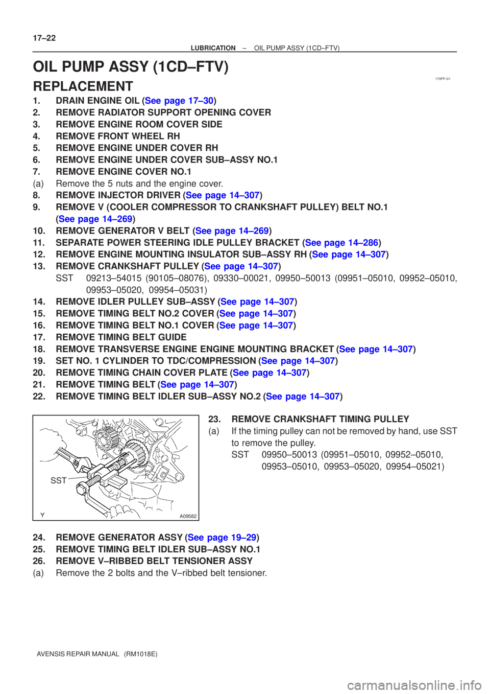
23.REMOVE CRANKSHAFT TIMING PULLEY
(a)If the timing pulley can not be removed by hand, use SSTto remove the pulley.
SST09950±50013 (09951±05010, 09952±05010, 09953±05010, 09953±05020, 09954±05021)
24.REMOVE GENERATOR ASSY(See page 19±29)
25. REMOVE TIMING BELT IDLER SUB±ASSY NO.1
26. REMOVE V±RIBBED BELT TENSIONER ASSY
(a) Remove the 2 bolts and the V±ribbed belt tensioner.
Page 2399 of 5135
B08009
A56697
A56698
A56699
17±24
± LUBRICATIONOIL PUMP ASSY (1CD±FTV)
AVENSIS REPAIR MANUAL (RM1018E)
31. REMOVE OIL PAN INSULATOR
(a) Remove the bolt and the oil pan insulator.
32. REMOVE OIL PAN SUB±ASSY
(a) Remove the 19 bolts and 3 nuts.
(b) Using a screwdriver, remove the oil pan by prying be-
tween the cylinder block and the No. 1 oil pan.
NOTICE:
Be careful not to damage the cylinder block and No. 1 oil
pan.
33. REMOVE CRANKSHAFT POSITION SENSOR
34. REMOVE OIL PUMP ASSY
(a) Remove the 9 bolts.
(b) Remove the oil pump by prying between the oil pump and
the main bearing cap with a screwdriver.
(c) Remove the gasket.
Page 2400 of 5135
A56700
SST
B07987
New Gasket
Seal
Packing Seal Width
2 to 4 mm
B08024
± LUBRICATIONOIL PUMP ASSY (1CD±FTV)
17±25
AVENSIS REPAIR MANUAL (RM1018E)
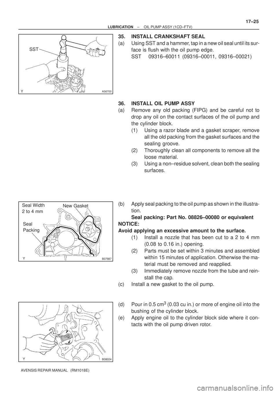
35. INSTALL CRANKSHAFT SEAL
(a) Using SST and a hammer, tap in a new oil seal until its sur-
face is flush with the oil pump edge.
SST 09316±60011 (09316±00011, 09316±00021)
36. INSTALL OIL PUMP ASSY
(a) Remove any old packing (FIPG) and be careful not to
drop any oil on the contact surfaces of the oil pump and
the cylinder block.
(1) Using a razor blade and a gasket scraper, remove
all the old packing from the gasket surfaces and the
sealing groove.
(2) Thoroughly clean all components to remove all the
loose material.
(3) Using a non±residue solvent, clean both the sealing
surfaces.
(b) Apply seal packing to the oil pump as shown in the illustra-
tion.
Seal packing: Part No. 08826±00080 or equivalent
NOTICE:
Avoid applying an excessive amount to the surface.
(1) Install a nozzle that has been cut to a 2 to 4 mm
(0.08 to 0.16 in.) opening.
(2) Parts must be set within 3 minutes and assembled
within 15 minutes of application. Otherwise the ma-
terial must be removed and reapplied.
(3) Immediately remove nozzle from the tube and rein-
stall the cap.
(c) Install a new gasket to the oil pump.
(d) Pour in 0.5 cm
3 (0.03 cu in.) or more of engine oil into the
bushing of the cylinder block.
(e) Apply engine oil to the cylinder block side where it con-
tacts with the oil pump driven rotor.
Page 2404 of 5135
SST
A09583
Inward
Angle Sensor
±
LUBRICATION OIL PUMP ASSY(1CD±FTV)
17±29
AVENSIS REPAIR MANUAL (RM1018E)
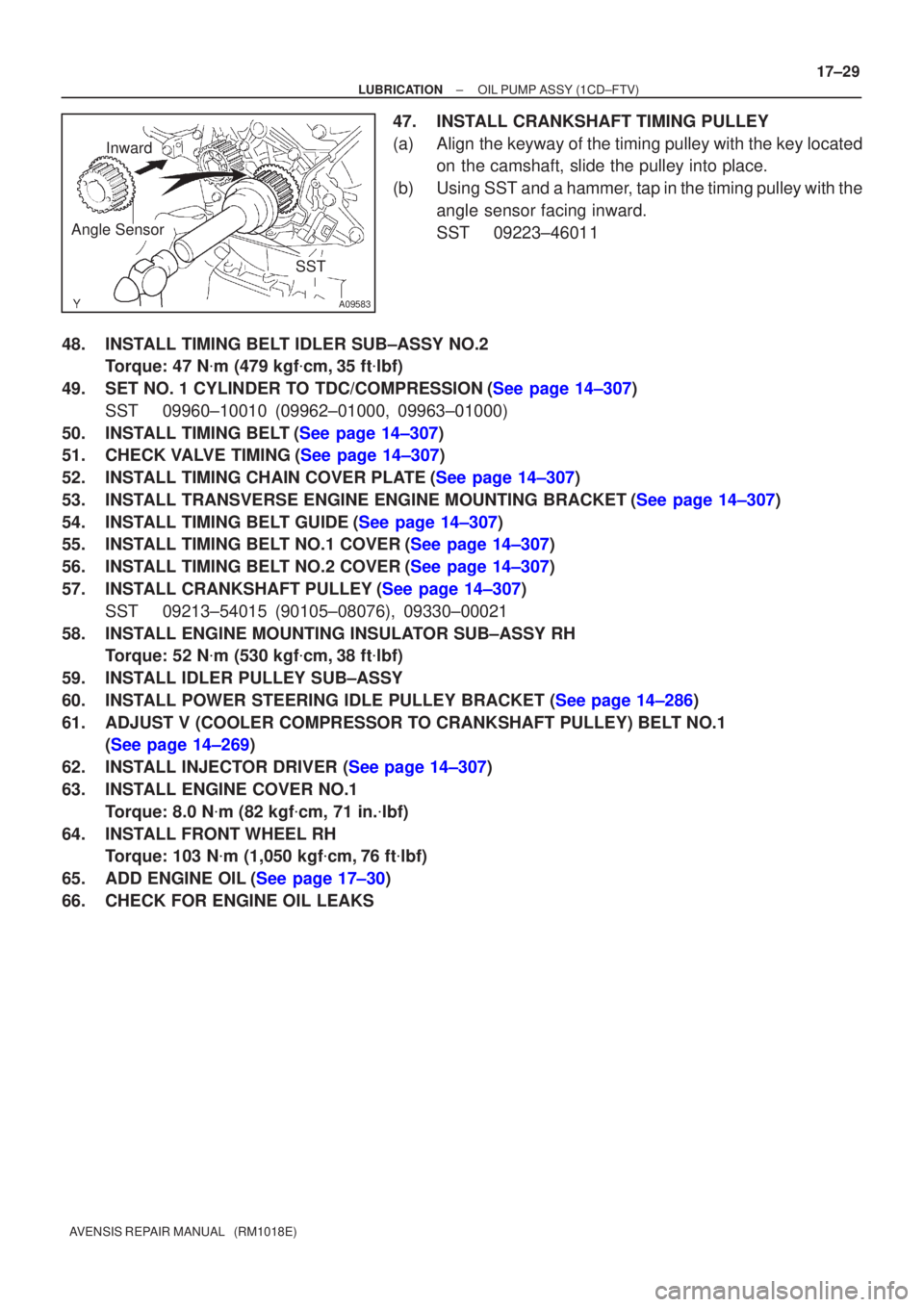
47.INSTALL CRANKSHAFT TIMING PULLEY
(a)Align the keyway of the timing pulley with the key located
on the camshaft, slide the pulley into place.
(b)Using SST and a hammer, tap in the timing pulley with the angle sensor facing inward.
SST09223±46011
48.INSTALL TIMING BELT IDLER SUB±ASSY NO.2 Torque: 47 N �m (479 kgf �cm,35 ft �lbf)
49.SET NO. 1 CYLINDER TO TDC/COMPRESSION(See page 14±307) SST 09960±10010 (09962±01000, 09963±01000)
50.INSTALL TIMING BELT(See page 14±307)
51.CHECK VALVE TIMING(See page 14±307)
52.INSTALL TIMING CHAIN COVER PLATE(See page 14±307)
53.INSTALL TRANSVERSE ENGINE ENGINE MOUNTING BRACKET(See page 14±307)
54.INSTALL TIMING BELT GUIDE(See page 14±307)
55.INSTALL TIMING BELT NO.1 COVER(See page 14±307)
56.INSTALL TIMING BELT NO.2 COVER(See page 14±307)
57.INSTALL CRANKSHAFT PULLEY(See page 14±307) SST 09213±54015 (90105±08076), 09330±00021
58. INSTALL ENGINE MOUNTING INSULATOR SUB±ASSY RH Torque: 52 N �m (530 kgf �cm, 38 ft �lbf)
59. INSTALL IDLER PULLEY SUB±ASSY
60.INSTALL POWER STEERING IDLE PULLEY BRACKET (See page 14±286)
61. ADJUST V (COOLER COMPRESSOR TO CRANKSHAFT PULLEY) BELT NO.1 (See page 14±269)
62.INSTALL INJECTOR DRIVER (See page 14±307)
63. INSTALL ENGINE COVER NO.1 Torque: 8.0 N �m (82 kgf �cm, 71 in. �lbf)
64. INSTALL FRONT WHEEL RH Torque: 103 N �m (1,050 kgf �cm, 76 ft �lbf)
65.ADD ENGINE OIL(See page 17±30)
66. CHECK FOR ENGINE OIL LEAKS
Page 2423 of 5135
170FR±01
B08737
A30890
±
LUBRICATION OIL PUMP ASSY(1ZZ±FE/3ZZ±FE)
17±3
AVENSIS REPAIR MANUAL (RM1018E)
OIL PUMP ASSY(1ZZ±FE/3ZZ±FE)
REPLACEMENT
1.DRAIN ENGINE OIL
(a)Remove the oil pan drain plug and drain engine oil.
2.REMOVAL & INSTALLATION CHAIN SUB±ASSY (See page 14±49)
3.REMOVE CHAIN VIBRATION DAMPER NO.1
(a)Remove the 2 bolts and the chain vibration damper No. 1.
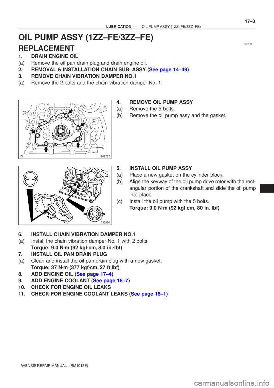
4.REMOVE OIL PUMP ASSY
(a)Remove the 5 bolts.
(b)Remove the oil pump assy and the gasket.
5.INSTALL OIL PUMP ASSY
(a)Place a new gasket on the cylinder block.
(b)Align the keyway of the oil pump drive rotor with the rect-angular portion of the crankshaft and slide the oil pump
into place.
(c)Install the oil pump with the 5 bolts. Torque: 9.0 N �m (92 kgf �cm, 80 in. �lbf)
6.INSTALL CHAIN VIBRATION DAMPER NO.1
(a)Install the chain vibration damper No. 1 with 2 bolts. Torque: 9.0 N �m (92 kgf �cm,8.0 in. �lbf)
7.INSTALL OIL PAN DRAIN PLUG
(a)Clean and install the oil pan drain plug with a new gasket.
Torque: 37 N �m (377 kgf �cm,27 ft �lbf)
8.ADD ENGINE OIL (See page 17±4)
9.ADD ENGINE COOLANT (See page 16±7)
10. CHECK FOR ENGINE OIL LEAKS
11.CHECK FOR ENGINE COOLANT LEAKS (See page 16±1)
Page 2428 of 5135
160ME±01
A79148
SST
16±46
±
COOLING WATER PUMP ASSY(1CD±FTV)
AVENSIS REPAIR MANUAL (RM1018E)
WATER PUMP ASSY(1CD±FTV)
REPLACEMENT
1.REMOVE RADIATOR SUPPORT OPENING COVER
2.REMOVE ENGINE ROOM COVER SIDE
3.DRAIN ENGINE COOLANT(See page 16±44)
4.REMOVE FRONT WHEEL RH
5.REMOVE ENGINE UNDER COVER SUB±ASSY NO.1
6.REMOVE ENGINE UNDER COVER RH
7.REMOVE ENGINE COVER NO.1
(a)Remove the 5 nuts and the engine cover.
8.REMOVE INJECTOR DRIVER (See page 14±286)
9.REMOVE V (COOLER COMPRESSOR TO CRANKSHAFT PULLEY) BELT NO.1 (See page 14±269)
10.REMOVE GENERATOR V BELT (See page 14±269)
11.SEPARATE POWER STEERING IDLE PULLEY BRACKET (See page 14±286)
12.SEPARATE ENGINE MOUNTING INSULATOR SUB±ASSY RH(See page 14±307)
13.REMOVE CRANKSHAFT PULLEY(See page 14±307) SST 09213±54015 (90105±08076), 09330±00021, 09950±50013 (0995\
1±05010, 09952±05010, 09953±05020, 09954±05031)
14. REMOVE IDLER PULLEY SUB±ASSY
(a) Remove the bolt, the washer and the pulley.
15.REMOVE TIMING BELT NO.2 COVER(See page 14±307)
16.REMOVE TIMING BELT NO.1 COVER(See page 14±307)
17. REMOVE TIMING BELT GUIDE
18.REMOVE TRANSVERSE ENGINE ENGINE MOUNTING BRACKET(See page 14±307)
19.SET NO. 1 CYLINDER TO TDC/COMPRESSION(See page 14±307)
20.REMOVE TIMING CHAIN COVER PLATE(See page 14±307)
21.REMOVE TIMING BELT(See page 14±307)
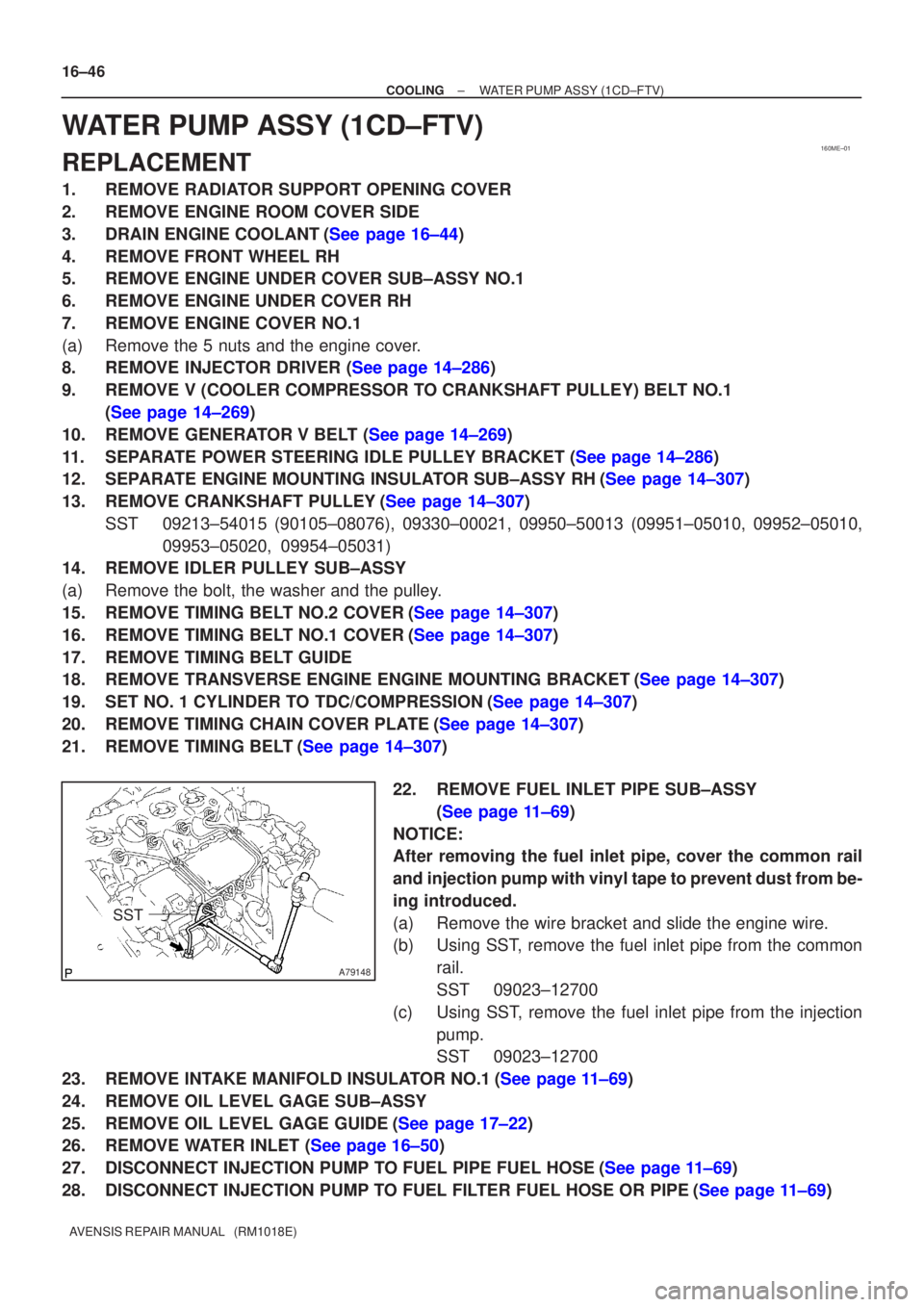
22. REMOVE FUEL INLET PIPE SUB±ASSY(See page 11±69)
NOTICE:
After removing the fuel inlet pipe, cover the common rail
and injection pump with vinyl tape to prevent dust from be-
ing introduced.
(a) Remove the wire bracket and slide the engine wire.
(b) Using SST, remove the fuel inlet pipe from the common rail.
SST 09023±12700
(c) Using SST, remove the fuel inlet pipe from the injection pump.
SST 09023±12700
23.REMOVE INTAKE MANIFOLD INSULATOR NO.1(See page 11±69)
24. REMOVE OIL LEVEL GAGE SUB±ASSY
25.REMOVE OIL LEVEL GAGE GUIDE(See page 17±22)
26.REMOVE WATER INLET (See page 16±50)
27.DISCONNECT INJECTION PUMP TO FUEL PIPE FUEL HOSE(See page 11±69)
28.DISCONNECT INJECTION PUMP TO FUEL FILTER FUEL HOSE OR PIPE(See page 11±69)
Page 2429 of 5135
A09580
8 mm
Hexagon
Wrench
A79170
A79170
A09581
8 mm
Hexagon
Wrench
Plate Washer
±
COOLING WATER PUMP ASSY(1CD±FTV)
16±47
AVENSIS REPAIR MANUAL (RM1018E)
29.REMOVE INJECTION PUMP DRIVE PULLEY(See page 11±69)
SST09960±10010 (09962±01000, 09963±01000), 09950±50013 (0995\
1±05010, 09952±05010, 09953±05020, 09954±05021)
30.REMOVE INJECTION OR SUPPLY PUMP ASSY(See page 11±69)
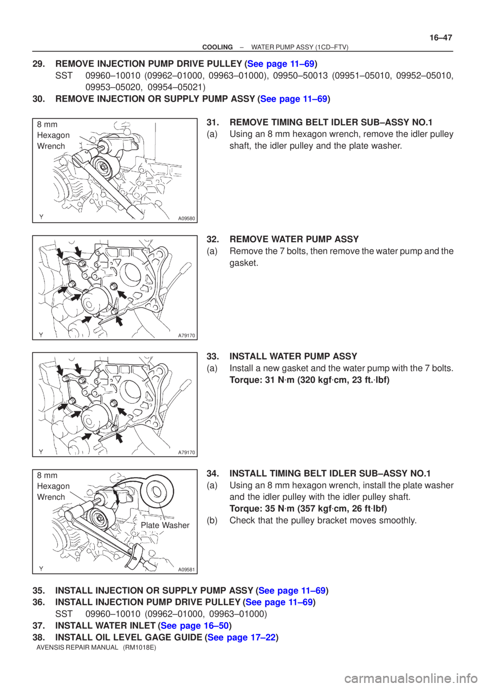
31.REMOVE TIMING BELT IDLER SUB±ASSY NO.1
(a)Using an 8 mm hexagon wrench, remove the idler pulleyshaft, the idler pulley and the plate washer.
32.REMOVE WATER PUMP ASSY
(a)Remove the 7 bolts, then remove the water pump and the gasket.
33.INSTALL WATER PUMP ASSY
(a)Install a new gasket and the water pump with the 7 bolts. Torque: 31 N �m (320 kgf �cm, 23 ft. �lbf)
34.INSTALL TIMING BELT IDLER SUB±ASSY NO.1
(a)Using an 8 mm hexagon wrench, install the plate washer and the idler pulley with the idler pulley shaft.
Torque: 35 N �m (357 kgf �cm, 26 ft �lbf)
(b)Check that the pulley bracket moves smoothly.
35.INSTALL INJECTION OR SUPPLY PUMP ASSY(See page 11±69)
36.INSTALL INJECTION PUMP DRIVE PULLEY(See page 11±69) SST 09960±10010 (09962±01000, 09963±01000)
37.INSTALL WATER INLET(See page 16±50)
38.INSTALL OIL LEVEL GAGE GUIDE(See page 17±22)