Page 2240 of 5135
A79423
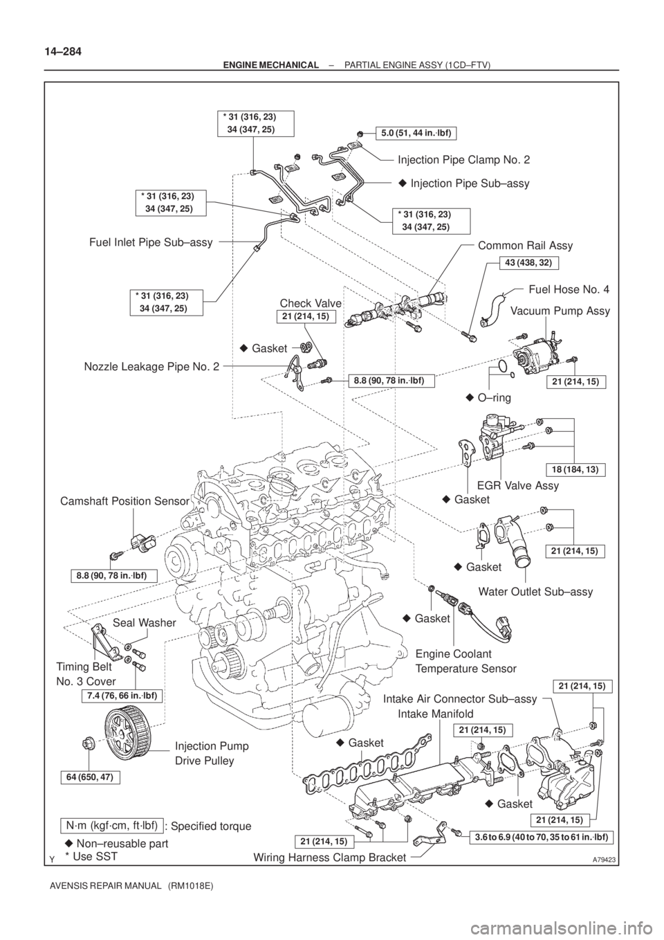
N´m (kgf´cm, ft´lbf)
: Specified torque
� Non±reusable part� Gasket
� O±ring
* Use SST� Gasket � Gasket
� Gasket
� Gasket
� Gasket3.6 to 6.9 (40 to 70, 35 to 61 in.�lbf)
5.0 (51, 44 in.�lbf)
7.4 (76, 66 in.�lbf)
* 31 (316, 23)
34 (347, 25)
43 (438, 32)
21 (214, 15)
18 (184, 13)
21 (214, 15)
21 (214, 15)
21 (214, 15)
64 (650, 47)
21 (214, 15)
* 31 (316, 23)
34 (347, 25)
* 31 (316, 23)
34 (347, 25)
Injection Pipe Clamp No. 2
� Injection Pipe Sub±assy
* 31 (316, 23)
34 (347, 25)
Common Rail Assy
Fuel Hose No. 4
Vacuum Pump Assy
Nozzle Leakage Pipe No. 2Fuel Inlet Pipe Sub±assy
EGR Valve Assy
Water Outlet Sub±assy
Engine Coolant
Temperature Sensor
Intake Air Connector Sub±assy
Intake Manifold
Wiring Harness Clamp Bracket Injection Pump
Drive Pulley Timing Belt
No. 3 CoverSeal Washer Camshaft Position Sensor
Check Valve
8.8 (90, 78 in.�lbf)
8.8 (90, 78 in.�lbf)
21 (214, 15)
21 (214, 15)
14±284
± ENGINE MECHANICALPARTIAL ENGINE ASSY (1CD±FTV)
AVENSIS REPAIR MANUAL (RM1018E)
Page 2244 of 5135
SST (A)
SST (B)
A09616
A09615
Magnetic
Finger
A54826
EXAMPLE (Intake):
Measured valve clearance = 0.45 mm (0.0177 in.)
0.45 mm (0.0177 in.) ± 0.25 mm (0.0098 in.) = 0.20 mm (0.0078 in.)
(Measured ± Specification = Excess clearance)
Used shim measurement = 2.80 mm (0.1102 in.)
0.20 mm (0.0078 in.) + 2.80 mm (0.1102 in.) = 3.00 mm (0.1181 in.)
(Excess clearance + Used shim = Ideal new shim)
Closest new shim = 3.00 mm (0.1181 in.)
Select No. 21 Shim
14±272
± ENGINE MECHANICALVALVE CLEARANCE (1CD±FTV)
AVENSIS REPAIR MANUAL (RM1018E)
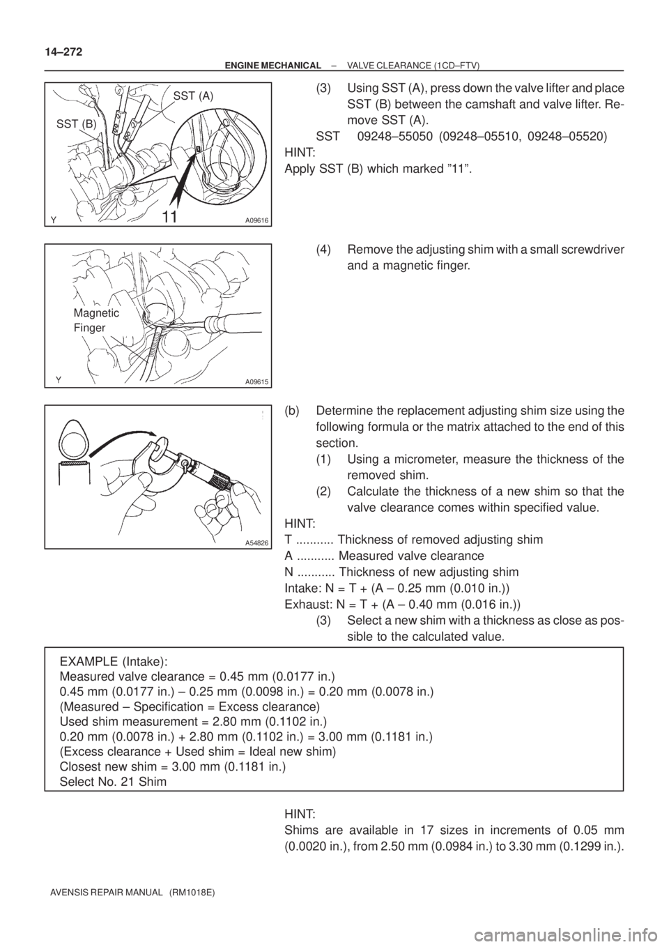
(3) Using SST (A), press down the valve lifter and place
SST (B) between the camshaft and valve lifter. Re-
move SST (A).
SST 09248±55050 (09248±05510, 09248±05520)
HINT:
Apply SST (B) which marked º11º.
(4) Remove the adjusting shim with a small screwdriver
and a magnetic finger.
(b) Determine the replacement adjusting shim size using the
following formula or the matrix attached to the end of this
section.
(1) Using a micrometer, measure the thickness of the
removed shim.
(2) Calculate the thickness of a new shim so that the
valve clearance comes within specified value.
HINT:
T ........... Thickness of removed adjusting shim
A ........... Measured valve clearance
N ........... Thickness of new adjusting shim
Intake: N = T + (A ± 0.25 mm (0.010 in.))
Exhaust: N = T + (A ± 0.40 mm (0.016 in.))
(3) Select a new shim with a thickness as close as pos-
sible to the calculated value.
HINT:
Shims are available in 17 sizes in increments of 0.05 mm
(0.0020 in.), from 2.50 mm (0.0984 in.) to 3.30 mm (0.1299 in.).
Page 2249 of 5135
141C1±01
A56434
AB
A56462
A56434
AB
±
ENGINE MECHANICAL DRIVE BELT(1CD±FTV)
14±269
AVENSIS REPAIR MANUAL (RM1018E)
DRIVE BELT(1CD±FTV)
REPLACEMENT
1.REMOVE RADIATOR SUPPORT OPENING COVER
2.REMOVE ENGINE ROOM COVER SIDE
3.REMOVE ENGINE UNDER COVER RH
4.REMOVE V (COOLER CO MPRESSOR TO
CRANKSHAFT PULLEY) BELT NO.1
(a)Loosen nut A and bolt B.
(b)Remove the V±ribbed belt.
5.REMOVE GENERATOR V BELT
(a)Turn the V±ribbed belt tensioner assy clockwise slowly, and remove the V±ribbed belt.
6.ADJUS T V (COOLER CO MPRESSOR TO
CRANKSHAFT PULLEY) BELT NO.1
(a)Install the V±ribbed belt.
(b)Tighten bolt B and adjust the drive belt tension. (See page 14±266)
(c) Tighten nut A. Torque: 38 N �m (390 kgf �cm, 28 ft �lbf)
Page 2250 of 5135
140DD±03
A57063
Measure Point for Belt
Deflection and Tension
Alternator
Crankshaft Compressor
P/S P/S
Alternator Crankshaft
A/C equipped
A/C not equipped
A61173
B
A
14±266
±
ENGINE MECHANICAL ENGINE(1CD±FTV)
AVENSIS REPAIR MANUAL (RM1018E)
ENGINE(1CD±FTV)
INSPECTION
1.INSPECT COOLANT (See page 16±37)
2.INSPECT ENGINE OIL (See page 17±20)
3.INSPECT BATTERY (See page 19±26)
4. INSPECT AIR CLEANER FILTER ELEMENT SUB±ASSY 5. INSPECT DRIVE BELT
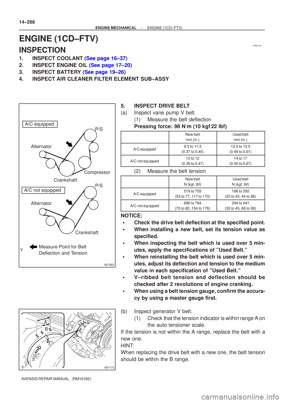
(a) Inspect vane pump V belt.(1) Measure the belt deflection
Pressing force: 98 N �m (10 kgf 22 lbf)
New belt
mm (in.)Used belt mm (in.)
A/C equipped9.5 to 11.5
(0.37 to 0.45)12.5 to 15.5
(0.49 to 0.61)
A/C not equipped10 to 12
(0.39 to 0.47)14 to 17
(0.55 to 0.67)
(2) Measure the belt tension
New belt
N (kgf, lbf)Used belt
N (kgf, lbf)
A/C equipped519 to 755
(53 to 77, 117 to 170)196 to 392
(20 to 40, 44 to 88)
A/C not equipped686 to 784
(70 to 80, 154 to 176)294 to 441
(30 to 45, 66 to 99)
NOTICE:
�Check the drive belt deflection at the specified point.
�When installing a new belt, set its tension value as
specified.
�When inspecting the belt which is used over 5 min-
utes, apply the specifications of ºUsed Belt.º
�When reinstalling the belt which is used over 5 min-
utes, adjust its deflection and tension to the medium
value in each specification of ºUsed Belt.º
�V±ribbed belt tension and deflection should be
checked after 2 revolutions of engine cranking.
�When using a belt tension gauge, confirm the accura-
cy by using a master gauge first.
(b) Inspect generator V belt. (1) Check that the tension indicator is within range A onthe auto tensioner scale.
If the tension is not within the A range, replace the belt with a
new one.
HINT:
When replacing the drive belt with a new one, the belt tension
should be within the B range.
Page 2253 of 5135
141BS±01
A77421
Cut Position
A77422SST
±
ENGINE MECHANICAL ENGINE REAR OIL SEAL(1AZ±FSE)
14±265
AVENSIS REPAIR MANUAL (RM1018E)
ENGINE REAR OIL SEAL(1AZ±FSE)
REPLACEMENT
1.REMOVE MANUAL TRANSAXLE ASSY (M/T TRANSAXLE) (See page 41±24)
2.REMOVE AUTOMATIC TRANSAXLE ASSY (A/T TRANSAXLE) (See page 40±25)
3.REMOVE CLUTCH COVER ASSY (M/T TRANSAXLE) (See page 42±26)
4.REMOVE DRIVE PLATE AND RING GEAR OR FLYWHEEL (See page 14±204)
SST09213±54015 (91651±60855), 09330±00021
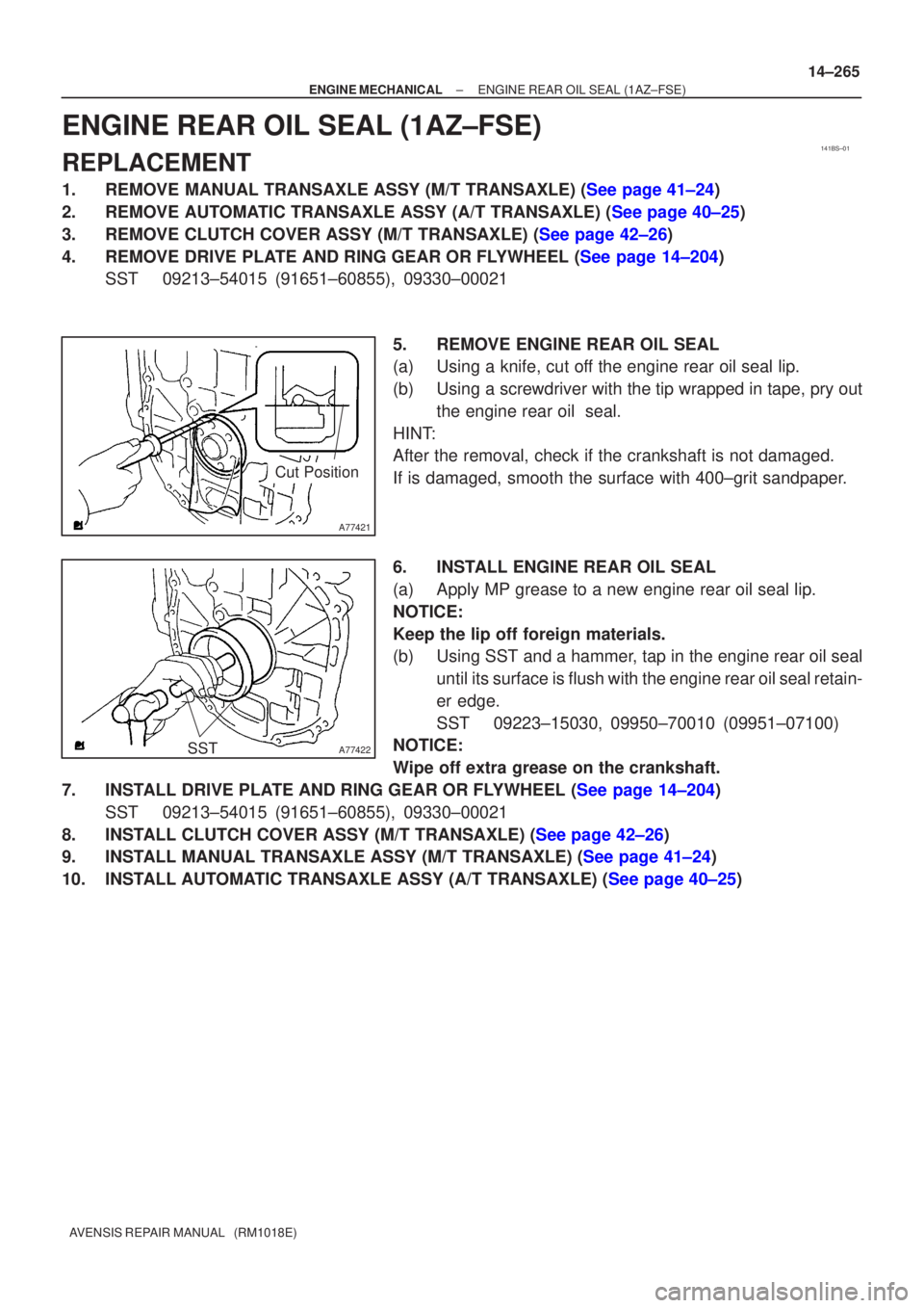
5.REMOVE ENGINE REAR OIL SEAL
(a)Using a knife, cut off the engine rear oil seal lip.
(b)Using a screwdriver with the tip wrapped in tape, pry outthe engine rear oil seal.
HINT:
After the removal, check if the crankshaft is not damaged.
If is damaged, smooth the surface with 400±grit sandpaper.
6.INSTALL ENGINE REAR OIL SEAL
(a)Apply MP grease to a new engine rear oil seal lip.
NOTICE:
Keep the lip off foreign materials.
(b)Using SST and a hammer, tap in the engine rear oil seal until its surface is flush with the engine rear oil seal retain-
er edge.
SST09223±15030, 09950±70010 (09951±07100)
NOTICE:
Wipe off extra grease on the crankshaft.
7.INSTALL DRIVE PLATE AND RING GEAR OR FLYWHEEL (See page 14±204) SST 09213±54015 (91651±60855), 09330±00021
8.INSTALL CLUTCH COVER ASSY (M/T TRANSAXLE) (See page 42±26)
9.INSTALL MANUAL TRANSAXLE ASSY (M/T TRANSAXLE) (See page 41±24)
10.INSTALL AUTOMATIC TRANSAXLE ASSY (A/T TRANSAXLE) (See page 40±25)
Page 2255 of 5135
Cut Position
A13332
A77419
SST
A13697
SST
SST
14±264
±
ENGINE MECHANICAL TIMING GEAR CASE OR TIMING CHAIN CASE OIL
SEAL(1AZ±FSE)
AVENSIS REPAIR MANUAL (RM1018E)
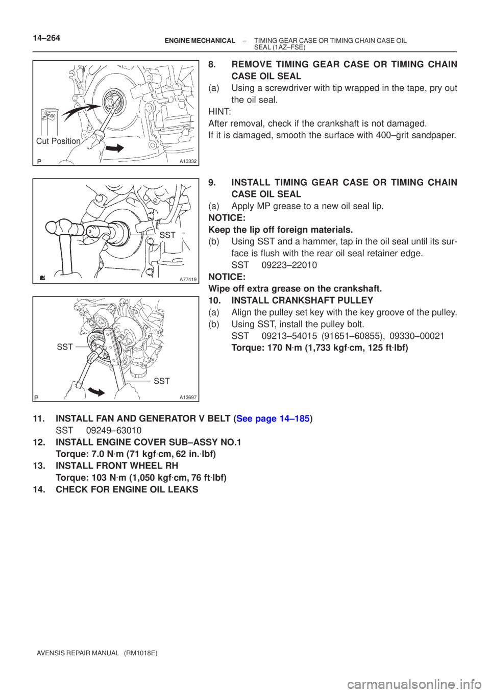
8.REMOVE TIMING GEAR CASE OR TIMING CHAIN CASE OIL SEAL
(a)Using a screwdriver with tip wrapped in the tape, pry out
the oil seal.
HINT:
After removal, check if the crankshaft is not damaged.
If it is damaged, smooth the surface with 400±grit sandpaper.
9.INSTALL TIMING GEAR CASE OR TIMING CHAIN CASE OIL SEAL
(a)Apply MP grease to a new oil seal lip.
NOTICE:
Keep the lip off foreign materials.
(b)Using SST and a hammer, tap in the oil seal until its sur- face is flush with the rear oil seal retainer edge.
SST09223±22010
NOTICE:
Wipe off extra grease on the crankshaft.
10.INSTALL CRANKSHAFT PULLEY
(a)Align the pulley set key with the key groove of the pulley.
(b)Using SST, install the pulley bolt. SST09213±54015 (91651±60855), 09330±00021
Torque: 170 N �m (1,733 kgf �cm, 125 ft �lbf)
11.INSTALL FAN AND GENERATOR V BELT (See page 14±185) SST 09249±63010
12. INSTALL ENGINE COVER SUB±ASSY NO.1 Torque: 7.0 N �m (71 kgf �cm, 62 in. �lbf)
13. INSTALL FRONT WHEEL RH Torque: 103 N �m (1,050 kgf �cm, 76 ft �lbf)
14. CHECK FOR ENGINE OIL LEAKS
Page 2269 of 5135
A77327
N´m (kgf´cm, ft´lbf)
: Specified torque
� Non±reusable part� Gasket
9.0 (90, 80 in.�lbf)
Chain Tensioner Assy No. 1
Timing Chain or Belt Cover Sub±assy
Crank Position Sensor
9.0 (90, 80 in.�lbf)
V±ribbed Belt Tensioner
Sub±assy
60 (610, 44)
60 (610, 44)
43 (440, 32)
170 (1,735, 125)
Crankshaft Pulley
Chain Sub±assy
43 (440, 32)
Chain Tensioner
Slipper
19 (195, 14)
Camshaft Position
Sensor Plate No. 1
Oil Pump
Drive Gear
Chain Vibration
Damper No. 1
� Oil Seal
Timing Chain Guide
9.0 (90, 80 in.�lbf)
Oil Pan Sub±assy
9.0 (90, 80 in.�lbf)
9.0 (90, 80 in.�lbf)
43 (440, 32)
43 (440, 32)
9.0 (90, 80 in.�lbf)
14±250
± ENGINE MECHANICALCYLINDER HEAD GASKET (1AZ±FSE)
AVENSIS REPAIR MANUAL (RM1018E)
Page 2280 of 5135
141CC±01
A61182
SST
A09447
SST
A09448
±
ENGINE MECHANICAL ENGINE REAR OIL SEAL(1CD±FTV)
14±345
AVENSIS REPAIR MANUAL (RM1018E)
ENGINE REAR OIL SEAL(1CD±FTV)
REPLACEMENT
1.REMOVE MANUAL TRANSAXLE ASSY (See page 41±33)
SST 09930±00010, 09628±62011, 09520±01010, 09520±24010 (09520±32040)
2.REMOVE CLUTCH COVER ASSY (See page 42±26)
3.REMOVE CLUTCH DISC ASSY (See page 42±26)
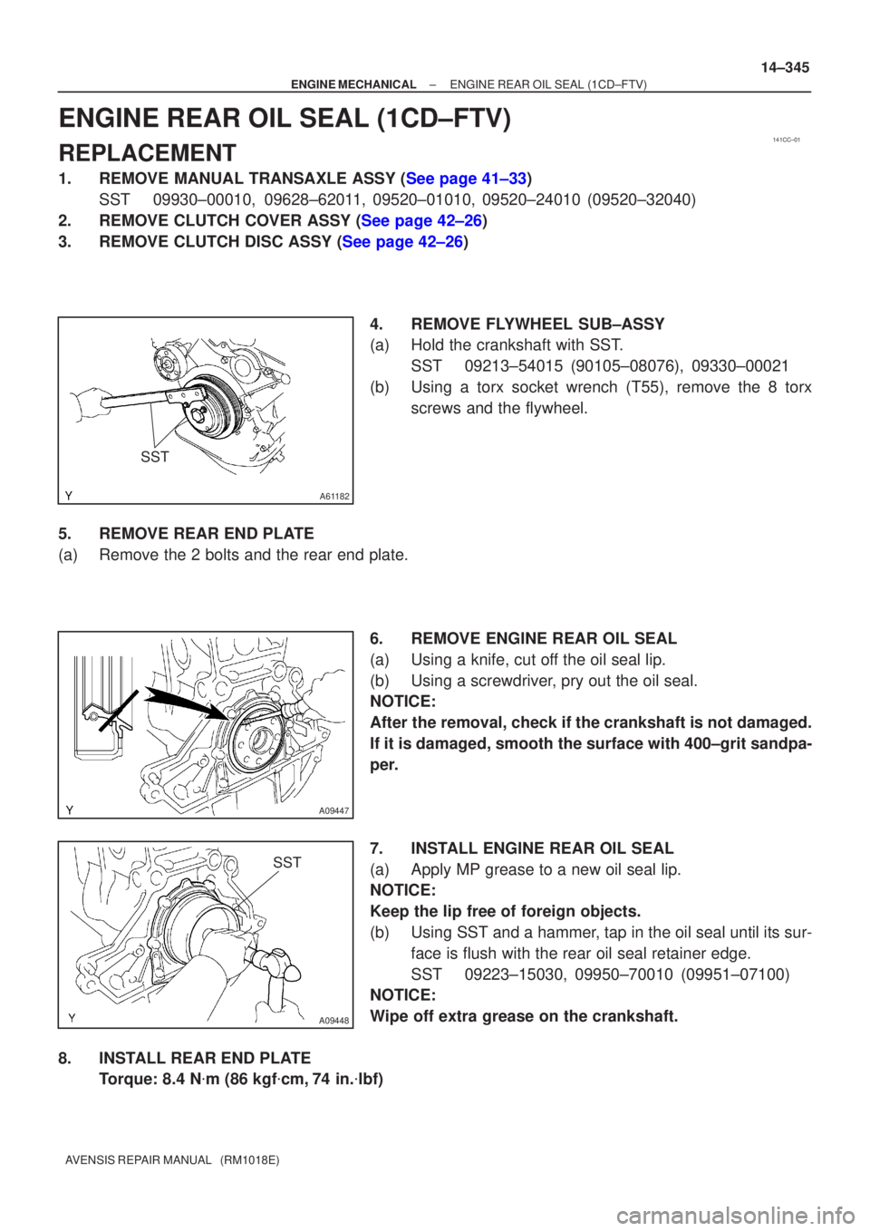
4. REMOVE FLYWHEEL SUB±ASSY
(a) Hold the crankshaft with SST.SST 09213±54015 (90105±08076), 09330±00021
(b) Using a torx socket wrench (T55), remove the 8 torx screws and the flywheel.
5. REMOVE REAR END PLATE
(a) Remove the 2 bolts and the rear end plate. 6. REMOVE ENGINE REAR OIL SEAL
(a) Using a knife, cut off the oil seal lip.
(b) Using a screwdriver, pry out the oil seal.
NOTICE:
After the removal, check if the crankshaft is not damaged.
If it is damaged, smooth the surface with 400±grit sandpa-
per.
7. INSTALL ENGINE REAR OIL SEAL
(a) Apply MP grease to a new oil seal lip.
NOTICE:
Keep the lip free of foreign objects.
(b) Using SST and a hammer, tap in the oil seal until its sur-face is flush with the rear oil seal retainer edge.
SST 09223±15030, 09950±70010 (09951±07100)
NOTICE:
Wipe off extra grease on the crankshaft.
8. INSTALL REAR END PLATE Torque: 8.4 N �m (86 kgf �cm, 74 in. �lbf)