Page 677 of 5135

A76568
I9
Diesel Turbo Inlet Air
Temperature Sensor2
1 GR
E2E1
THIA
R5V
ECM
E13 E13
20
28
BR
05±574
±
DIAGNOSTICS ECD SYSTEM(1CD±FTV)
AVENSIS REPAIR MANUAL (RM1018E)
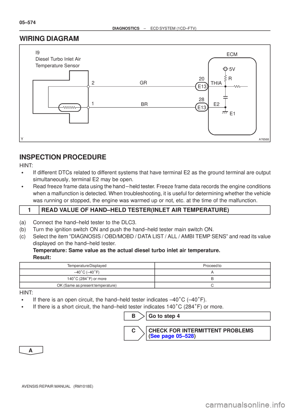
WIRING DIAGRAM
INSPECTION PROCEDURE
HINT:
�If different DTCs related to different systems that have terminal E2 as the ground terminal are output
simultaneously, terminal E2 may be open.
�Read freeze frame data using
\b�\b�
��\b� �
�\f
��� Freeze frame data records the engine conditions
when a malfunction is detected. When troubleshooting, it is useful for d\
etermining whether the vehicle
was running or stopped, the engine was warmed up or not, etc. at the time o\
f the malfunction.
1READ VALUE OF HAND±HELD TESTER(INLET AIR TEMPERATURE)
(a)Connect the hand±held tester to the DLC3.
(b)Turn the ignition switch ON and push the hand±held tester main switch \
ON.
(c)Select the item ºDIAGNOSIS / OBD/MOBD / DATA LIST / ALL / AMBI TEMP SENSº and read its value displayed on the hand±held tester.
Temperature: Same value as the actual diesel turbo inlet air temperature.\
Result:
Temperature DisplayedProceed to
±40�C (±40 ��)A
140 �C (284 ��) or moreB
OK (Same as present temperature)C
HINT:
�If there is an open circuit, the hand±held tester indicates ±40 �C (±40 �F).
�If there is a short circuit, the hand±held tester indicates 140 �C (284 �F) or more.
BGo to step 4
CCHECK FOR INTERMITTENT PROBLEMS (See page 05±528)
A
Page 687 of 5135

A80998
F16
Fuel Pressure Sensor
5
P
PCR1ECM
E1326 5
EB1
2
P±B
PCR2
E1333 2
EB1
1
R±W
VCS
E122 1
EB1
6
R±W
VC
E1318 6
EB1
3
BR
E2S
E121 3
EB1
4
BR
E2
E1328 4
EB1 PR
PR2P
P±B
R±W
R±W
BR
BR VC
E2S VCS
E2
± DIAGNOSTICSECD SYSTEM (1CD±FTV)
05±561
AVENSIS REPAIR MANUAL (RM1018E)
WIRING DIAGRAM
INSPECTION PROCEDURE
HINT:
�After completing repair, confirm P0087 is not set again.
�If different DTCs related to different systems that have terminal E2 as the ground terminal are output
simultaneously, terminal E2 may be open.
�Read freeze frame data using the hand±held tester. Freeze frame data records the engine conditions
when a malfunction is detected. When troubleshooting, it is useful for determining whether the vehicle
was running or stopped, the engine was warmed up or not, etc. at the time of the malfunction.
1 READ VALUE OF HAND±HELD TESTER(FUEL PRESSURE)
(a) Connect the hand±held tester to the DLC3.
(b) Turn the ignition switch ON and push the hand±held tester main switch ON.
(c) Start the engine.
(d) Select the item ºDIAGNOSIS / OBD/MOBD / DATA LIST / ALL / COMN RAIL PRESSº.
(e) Check that internal fuel pressure of the common rail is within specification below.
Reference:
Engine SpeedFuel Pressure (MPa)
IdlingApprox. 30 to 40
Running the engine at 2,500 rpm (No engine load)Approx. 50 to 100
NG Go to step 3
OK
Page 689 of 5135

A66060
E13
ECM ConnectorE12
VN(+)E1(±)
A82974
VRV Signal Waveforms
GND
5V/
Division
1 msec./ Division
05±554
±
DIAGNOSTICS ECD SYSTEM(1CD±FTV)
AVENSIS REPAIR MANUAL (RM1018E)
DTCP0045TURBO/SUPER CHARGER BOOST CONTROL SOLENOID CIRCUIT / OPEN
CIRCUIT DESCRIPTION
DTC No.DTC Detection ConditionTrouble Area
P0045Open or short in VRV circuit for 0.5sec. or more
(1 trip detection logic)�VRV
� Open or short in VRV circuit
� ECM
WIRING DIAGRAM
Refer to DTC P0234 on page 05±612.
INSPECTION PROCEDURE
HINT:
Read freeze frame data using �����\b��������
�� . Freeze frame data records the engine conditions when
a malfunction is detected. When troubleshooting, it is useful for determi\
ning whether the vehicle was running
or stopped, the engine was warmed up or not, etc. at the time of the malfu\
nction.
1INSPECT VACUUM REGULATING VALVE ASSY (See page 12±16)
NGREPLACE VACUUM REGULATING VALVE ASSY
OK
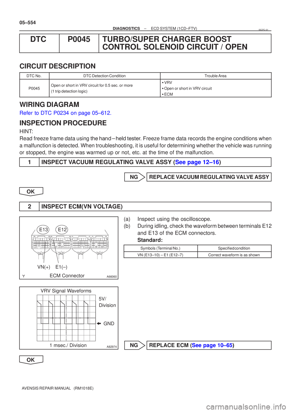
2INSPECT ECM(VN VOLTAGE)
(a)Inspect using the oscilloscope.
(b)During idling, check the waveform between terminals E12 and E13 of the ECM connectors.
Standard:
Symbols (Terminal No.)Specified condition
VN (E13±10) ± E1 (E12±7)Correct waveform is as shown
NGREPLACE ECM (See page 10±65)
OK
05CPC±01
Page 693 of 5135
A81009
STP E10 G±W
6
4 B±RDriver
Side J/B
1
ED1 21
1
2 AM2
ALT B
2 IR1
B±L19
B
BatteryDriver
Side J/B Engine Room
R/B No. 3
FL MAIN 3
STOP 1
11A
3
3
W Engine Room
R/B No. 1
22 DA
1 DN 11 IE3
R±W
(LHD)R±W
(LHD)
R±W
(RHD)R±W
(RHD)
3 IR1
B±W
(RHD)B±W
(RHD)
20 IE1
B±W
(LHD)B±W
(LHD) 3 24 1
S13
Stop Lamp Switch
B±W B±W
C J9 (LHD)
E J27 (RHD)
J/C
C J8 (LHD)
A J26 (RHD) Driver
Side J/BIGN I13
Ignition Switch
AM2 IG2
B±R
B±R(LHD)
(RHD) 1 IE4
1IP1
18 DA2 DHECM
ST1± E1012 DA2
DC10
1 IR1 6 IE3
G±W
(LHD)G±W
(LHD)
G±W
(RHD)G±W
(RHD)
4 IR1
G±W
(RHD)G±W
(RHD)
14 IE2
G±W
(LHD)G±W
(LHD) 05±644
± DIAGNOSTICSECD SYSTEM (1CD±FTV)
AVENSIS REPAIR MANUAL (RM1018E)
WIRING DIAGRAM
INSPECTION PROCEDURE
HINT:
Read freeze frame data using ��� ��������� ��
�� . Freeze frame data records the engine conditions when
a malfunction is detected. When troubleshooting, it is useful for determining whether the vehicle was running
or stopped, the engine was warmed up or not, etc. at the time of the malfunction.
Page 697 of 5135
A81008
ECM
E10 17
V±W
C11
Combination
Meter Assy
(RHD)
V±W
18
J20H
J/C
SP1
(RHD) J20
H
(LHD) J10
H
(LHD)J10
H
±
DIAGNOSTICS ECD SYSTEM(1CD±FTV)
05±641
AVENSIS REPAIR MANUAL (RM1018E)
WIRING DIAGRAM
INSPECTION PROCEDURE
HINT:
Read freeze frame data using �����\b��������
�� . Freeze frame data records the engine conditions when
a malfunction is detected. When troubleshooting, it is useful for determi\
ning whether the vehicle was running
or stopped, the engine was warmed up or not, etc. at the time of the malfu\
nction.
1CHECK OPERATION OF SPEEDOMETER
(a)Drive the vehicle and check if the operation of the speedometer in the combination meter is normal.
HINT:
The vehicle speed sensor is operating normally if the speedometer displa\
y is normal.
NGCHECK SPEEDOMETER CIRCUIT (See page 05±1510)
OK
Page 701 of 5135

A81906
ECM
D1
Intake Shutter
B
LU+A 15
E13
G
Y
LE13
E13
E1314
13
12LU±A
LU+B
LU±B 6
4
3
1From EFI MAIN Relay
5
2B±W
B±W
B±W
P±L
E1311
THOP 1
2 W±B
EIT3
Intake Shutter
Fully Opened Switch
± DIAGNOSTICSECD SYSTEM (1CD±FTV)
05±635
AVENSIS REPAIR MANUAL (RM1018E)
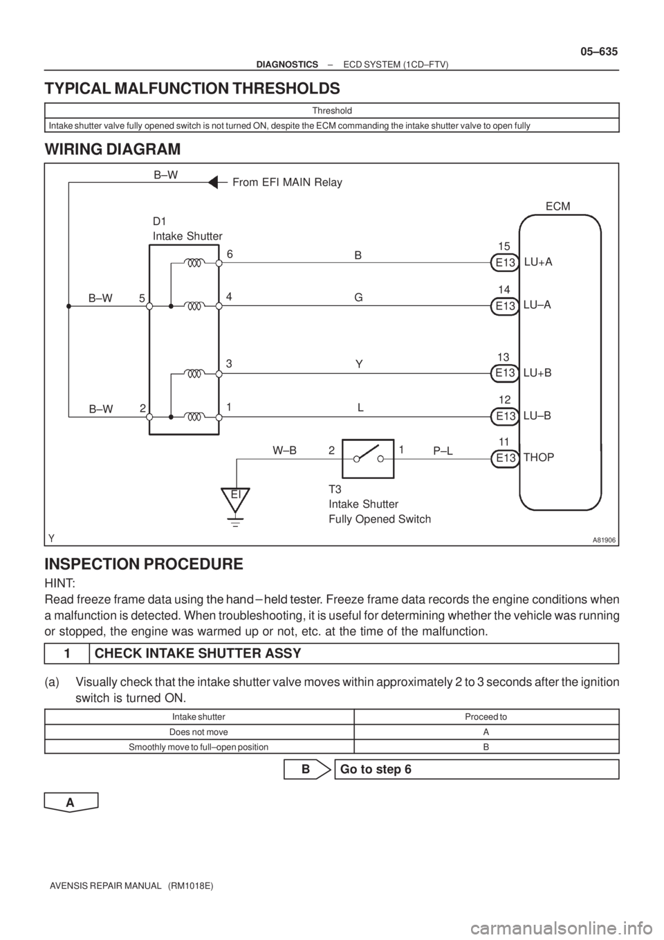
TYPICAL MALFUNCTION THRESHOLDS
Threshold
Intake shutter valve fully opened switch is not turned ON, despite the ECM commanding the intake shutter valve to open fully
WIRING DIAGRAM
INSPECTION PROCEDURE
HINT:
Read freeze frame data using ��� �� ������ �����
� Freeze frame data records the engine conditions when
a malfunction is detected. When troubleshooting, it is useful for determining whether the vehicle was running
or stopped, the engine was warmed up or not, etc. at the time of the malfunction.
1 CHECK INTAKE SHUTTER ASSY
(a) Visually check that the intake shutter valve moves within approximately 2 to 3 seconds after the ignition
switch is turned ON.
Intake shutterProceed to
Does not moveA
Smoothly move to full±open positionB
B Go to step 6
A
Page 706 of 5135
A81006
ECM
E3
EGR Valve Assy
G
EG+A 6
E12
Y±G
R±L
G±BE12
E12
E125
4
3EG±A
EG+B
EG±B 6
4
3
1From EFI MAIN Relay
5
2B±W
B±W
B±W
± DIAGNOSTICSECD SYSTEM (1CD±FTV)
05±629
AVENSIS REPAIR MANUAL (RM1018E)
DTC P0400 EXHAUST GAS RECIRCULATION FLOW
DTC P0403 EXHAUST GAS RECIRCULATION CONTROL
CIRCUIT
CIRCUIT DESCRIPTION
DTC No.DTC Detection ConditionTrouble Area
P0400Mass air flow rate is not changed when turning on EGR valve�EGR valve assy
�Open or short in EGR circuit
P0403EGR valve assy motor malfunction
�Oen or short in EGR circuit
�EGR passage
�ECM
WIRING DIAGRAM
INSPECTION PROCEDURE
HINT:
Read freeze frame data using ��� �� ������ �����
� Freeze frame data records the engine conditions when
a malfunction is detected. When troubleshooting, it is useful for determining whether the vehicle was running
or stopped, the engine was warmed up or not, etc. at the time of the malfunction.
05CPU±01
Page 712 of 5135
A81005
ECM
ALT 8
E13
IK1 G±Y
G2
GLOW
Relay1
2 3
G1
Glow Plug110
GLOW
Battery
EI R
4 B±L
B
FL
MAIN
BR B
ALT
12
12
33
BB
Engine Room
R/B No. 3
IJBR BR
B
B 3
333
1 25 15DH
DN 1 DH
18DB 9 DA ECU±IG I13
Ignition Switch 3
1
AM1AM1 IG1
G±R
ED1 1
WDriver
Side J/B
IG1
RelayA12 1
BB±L
A11 3
MY
A11 4
LRL 9
E12
Generator
IG S
2A11
1 A11 A11
R±W B
IK21
EE1 5GREL 14
E9
R
R
B
R±W R±W
W±B
G J10(LHD)
C J20(RHD)
J/C
G J10(LHD)
C J20(RHD)
ALT±SEFI
1 2
1 2 11
11AEngine
Room
R/B No. 1 IE3 7 (LHD)
(RHD)
IO1 7BATT 2
E10
E1 7
E12 B±Y
B±Y
B 05±624
± DIAGNOSTICSECD SYSTEM (1CD±FTV)
AVENSIS REPAIR MANUAL (RM1018E)
WIRING DIAGRAM