Page 611 of 5135

A54292
T1
Throttle Control Motor
(Built in Throttle Body)
2
1B
WECM
3
2
17M+
M±
E11
(Shielded)
E11
E11
GE01
± DIAGNOSTICSSFI SYSTEM (1AZ±FSE)
05±483
AVENSIS REPAIR MANUAL (RM1018E)
DTC P2102 THROTTLE ACTUATOR CONTROL MOTOR
CIRCUIT LOW
DTC P2103 THROTTLE ACTUATOR CONTROL MOTOR
CIRCUIT HIGH
CIRCUIT DESCRIPTION
The throttle motor is operated by the ECM and it opens and closes the throttle valve.
The opening angle of the throttle valve is detected by the throttle position sensor which is mounted on the
throttle body. It provides feedback to the ECM to control the throttle motor in order to regulate the throttle
valve opening angle properly in response to the driving condition.
If this malfunction is detected, the ECM shuts down the power for the throttle motor, and the throttle valve
is closed by the return spring. And the throttle valve is locked at a certain opening angle. Also, the whole
electronically controlled throttle operation is cancelled until the system returns to normal and the ignition
switch is turned OFF.
HINT:
This electrical throttle system does not use the throttle cable.
DTC No.DTC Detection ConditionTrouble Area
P2102
Conditions (a) and (b) continue for 2.0 seconds:
(a) Throttle control motor output duty greater than 80 %
(b) Throttle control motor current less than 0.5 A�Open in throttle control motor circuit
�Throttle control motor
�ECM
Throttle control motor current greater than 10 A�Short in throttle control motor circuit
P2103Condition (a) continues for 0.6 seconds:
(a) Throttle control motor current greater than 7 A
Short in throttle control motor circuit
�Throttle control motor
�ECM
WIRING DIAGRAM
05CKP±01
Page 613 of 5135
A76875
ECM
SCV 5
E13 EFI Relay
1 1 23
Engine Room
J/B No. 4B±W
1MREL 8
E9
Battery FL MAIN B±G2 5
GR
V6
VSV (Intake Air Control Valve)
2
L±B EFI No. 2 1
B±G
W±B
ECW±B
4A
14B11AEFI
1B±Y
1
2 4
4
44
4
4
B±W Engine Room
R/B No. 1
and
Engine Room
J/B No. 1Engine Room R/B No. 4
GR
B±W
EA113IE1 2 05±480
± DIAGNOSTICSSFI SYSTEM (1AZ±FSE)
AVENSIS REPAIR MANUAL (RM1018E)
DTC P2008 INTAKE MANIFOLD RUNNER CONTROL
CIRCUIT / OPEN (BANK 1)
CIRCUIT DESCRIPTION
The Intake Air Control valve (IACV) is opened and shut by the actuator with intake manifold vacuum.
It stabilizes the engine combustion. The IACV operation generates swirl air flow in the cylinder.
DTC No.DTC Detection ConditionTrouble Area
P2008Open or short in VSV for IACV circuit 0.5 sec. or more
(2 trip detection logic)�Open of short in VSV for IACV circuit
�VSV for IACV
�ECM
WIRING DIAGRAM
05CK5±01
Page 616 of 5135

A76876
ECM
J13G
FP+ 6
R
E12
D(Shielded)
J13 E
J12 E J12D
BRBR
EEJ/C21 S3
Fuel Pump
(High Pressure)
(Spill Valve)
G
FP± 3
E12
(Shielded) BR
± DIAGNOSTICSSFI SYSTEM (1AZ±FSE)
05±477
AVENSIS REPAIR MANUAL (RM1018E)
DTC P1235 HIGH PRESSURE FUEL PUMP CIRCUIT
CIRCUIT DESCRIPTION
The fuel pump (high pressure) is an electronically controlled plunger type fuel pump (high pressure) which
is driven by the cam provided on the intake cam shaft rear end on the cylinder head.
The fuel pump (high pressure) increases the pressure of the fuel fed from the fuel pump (low pressure) in
the fuel tank at 8 to 13 MPa (81.6 to 132.6 kgf/cm
2, 1,160 to 1,885 psi) according to the operating condition,
and it feeds the fuel to the fuel delivery pipe.
DTC No.DTC Detection conditionTrouble Area
O h ti f l (hi h ) i itf 1�Open or short in fuel pump (high pressure)
P1235Open or short in fuel pump (high pressure) circuit for 1sec. or
more
�Oen or short in fuel um (high ressure)
�Fuel pump (high pressure)P1235moreFuel um (high ressure)
�ECM
WIRING DIAGRAM
INSPECTION PROCEDURE
HINT:
Read freeze frame data using hand±held tester. Freeze frame data records the engine conditions when the
malfunction is detected. When troubleshooting, it is useful for determining whether the vehicle was running
or stopped, the engine was warmed up or not, the air±fuel ratio was lean or rich, etc. at the time of the mal-
function.
05CK4±01
Page 622 of 5135

054KK±04
A66714
E13E12E10
E9
±
DIAGNOSTICS ECD SYSTEM (1CD±FTV)
05±549
AVENSIS REPAIR MANUAL (RM1018E)
TERMINALS OF ECM
Symbols (Terminal No.)Wiring ColorConditionSTD Voltage (V)
BATT (E10±2) ± E1 (E12±7)B±Y ± BRAlways9 to 14
IGSW (E9±9) ± E1 (E12±7)B±W ± BRIG switch ON9 to 14
+B (E9±1) ± E1 (E12±7)B±W ± BRIG switch ON9 to 14
MREL (E9 8) E1 (E12 7)GR BRIG switch ON9 to 14MREL (E9±8) ± E1 (E12±7)GR ± BRIG switch OFF0 to 1.5
VC (E13±18) ± E1 (E12±7)R±W ± BRIG switch ON4.5 to 5.5
VPA (E9 22) EPA (E9 28)GYIG switch ON, accelerator pedal fully released0.5 to 1.1VPA (E9±22) ± EPA (E9±28)G ± YIG switch ON, accelerator pedal fully depressed3.0 to 4.6
VPA2 (E9 23) EPA2 (E9 29)WYIG switch ON, accelerator pedal fully released0.9 to 2.3VPA2 (E9±23) ± EPA2 (E9±29)W ± YIG switch ON, accelerator pedal fully depressed3.4 to 5.0
VCPA (E9±26) ± EPA (E9±28)B ± YIG switch ON4.5 to 5.5
VCP2 (E9±27) ± EPA2 (E9±29)B ± YIG switch ON4.5 to 5.5
VG (E12±24) ± EVG (E12±32)G ± L±YIdling0.5 to 3.4
THA (E13±31) ± E2 (E13±28)G±R ± BRIdling, intake air temp. at 20 �C (68 �F)0.5 to 3.4
THW (E13±19) ± E2 (E13±28)B±W ± BRIdling, engine coolant temp. at 80 �C (176 �F)0.2 to 1.0
STA (E9±7) ± E1 (E12±7)B±Y ± BRCranking6.0 or more
#1 (E13±24) ± E1 (E12±7)
#2 (E13±23) ± E1 (E12±7)G±W ± BR
W±R ± BR
IdlingPulse generation#2 (E13 23) E1 (E12 7)
#3 (E13±22) ± E1 (E12±7)
#4 (E13±21) ± E1 (E12±7)
WR BR
R±W ± BR W±L ± BRIdlingPulse generation
(See page 05±604)
G1 (E12±23) ± G± (E12±31)P ± LIdlingPulse generation
(See page 05±616)
NE+ (E13±27) ± NE± (E13±34)G ± RIdlingPulse generation
(See page 05±616)
STP (E10 19) E1 (E12 7)GW BRIG switch on, brake pedal is depressed7.5 to 14STP (E10±19) ± E1 (E12±7)G±W ± BRIG switch on, brake pedal is released0 to 1.5
ST1 (E10 12) E1 (E12 7)GW BRBrake pedal is depressed0 to 1.5ST1± (E10±12) ± E1 (E12±7)G±W ± BRBrake pedal is released7.5 to 14
TC (E9 11) E1 (E12 7)WL BRIG switch ON9to14TC (E9±11) ± E1 (E12±7)W±L ± BRIG switch ON9 to 14
W (E9 12) E1 (E12 7)WBRIdling9 to 14W (E9±12) ± E1 (E12±7)W ± BRIG switch ON0 to 3
SP1 (E10±17) ± E1 (E12±7)V±W ± BRIG switch ON, rotate driving wheel slowlyPulse generation
(See page 05±640)
SIL (E9±18) ± E1 (E12±7)W±G ± BRConnect the hand±held tester to the DLC3Pulse generation
Page 658 of 5135

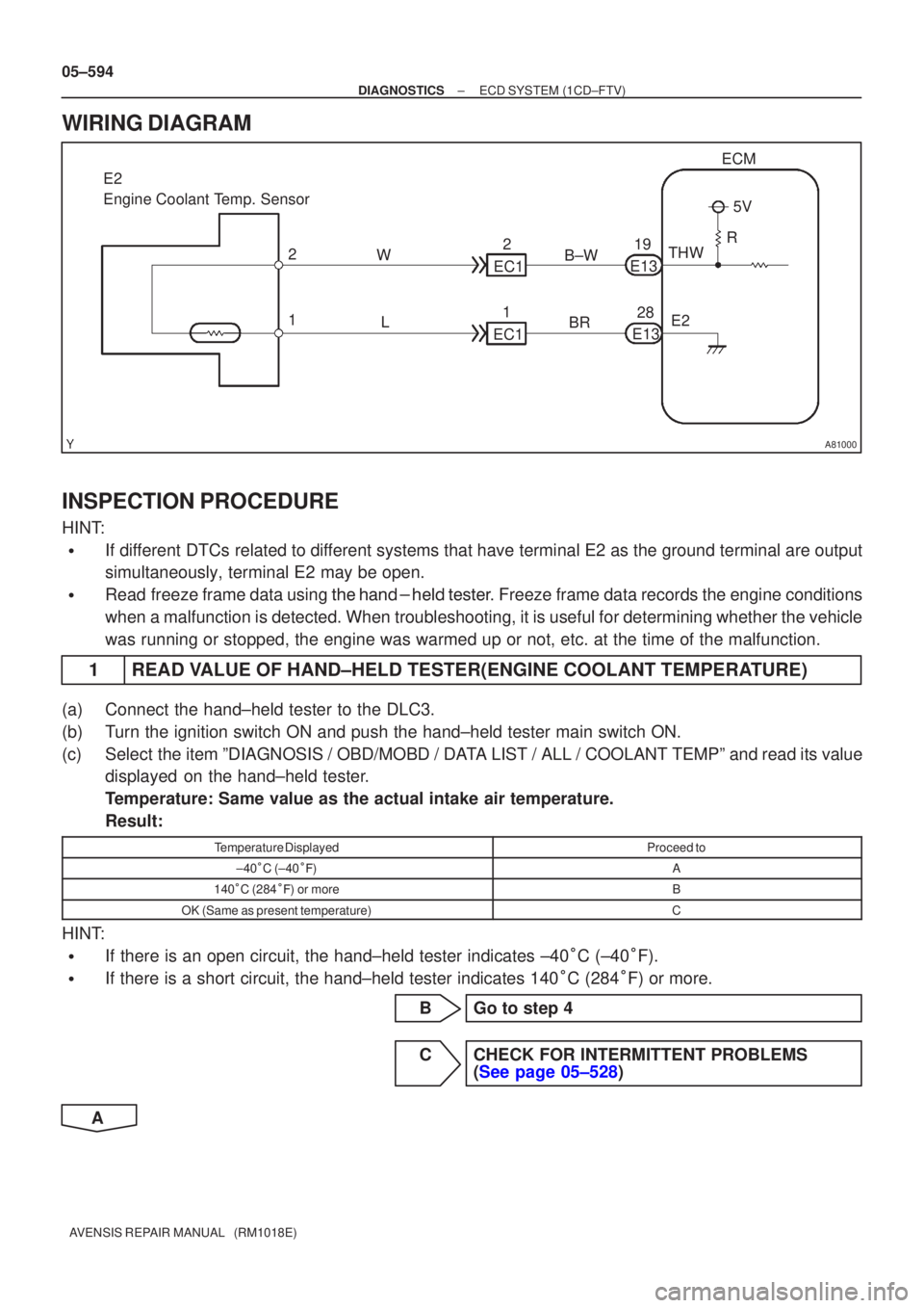
A81000
ECM
THW E2
19
E13
28
E13
L
W
1 2
E2
Engine Coolant Temp. Sensor
5V
R
BR
B±W
2
EC1
1
EC1
05±594
±
DIAGNOSTICS ECD SYSTEM(1CD±FTV)
AVENSIS REPAIR MANUAL (RM1018E)
WIRING DIAGRAM
INSPECTION PROCEDURE
HINT:
�If different DTCs related to different systems that have terminal E2 as the ground terminal are output
simultaneously, terminal E2 may be open.
�Read freeze frame data using \f���� ����\b�\f��\f�
. Freeze frame data records the engine conditions
when a malfunction is detected. When troubleshooting, it is useful for d\
etermining whether the vehicle
was running or stopped, the engine was warmed up or not, etc. at the time o\
f the malfunction.
1READ VALUE OF HAND±HELD TESTER(ENGINE COOLANT TEMPERATURE)
(a)Connect the hand±held tester to the DLC3.
(b)Turn the ignition switch ON and push the hand±held tester main switch \
ON.
(c)Select the item ºDIAGNOSIS / OBD/MOBD / DATA LIST / ALL / COOLANT TEMPº and read its value displayed on the hand±held tester.
Temperature: Same value as the actual intake air temperature.
Result:
Temperature DisplayedProceed to
±40
C (±40
�)A
140
C (284
�) or moreB
OK (Same as present temperature)C
HINT:
�If there is an open circuit, the hand±held tester indicates ±40
C (±40
F).
�If there is a short circuit, the hand±held tester indicates 140
C (284
F) or more.
BGo to step 4
CCHECK FOR INTERMITTENT PROBLEMS (See page 05±528)
A
Page 662 of 5135

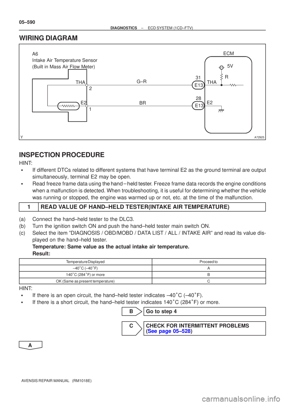
A72925
BR
G±R
28
31
E13 THA
E2 ECM
1 2
A6
Intake Air Temperature Sensor
(Built in Mass Air Flow Meter)
E135V
R
THA
E2
05±590
±
DIAGNOSTICS ECD SYSTEM(1CD±FTV)
AVENSIS REPAIR MANUAL (RM1018E)
WIRING DIAGRAM
INSPECTION PROCEDURE
HINT:
�If different DTCs related to different systems that have terminal E2 as the ground terminal are output
simultaneously, terminal E2 may be open.
�Read freeze frame data using
\b�\b�
��\b� �
�\f
��� Freeze frame data records the engine conditions
when a malfunction is detected. When troubleshooting, it is useful for d\
etermining whether the vehicle
was running or stopped, the engine was warmed up or not, etc. at the time o\
f the malfunction.
1READ VALUE OF HAND±HELD TESTER(INTAKE AIR TEMPERATURE)
(a)Connect the hand±held tester to the DLC3.
(b)Turn the ignition switch ON and push the hand±held tester main switch \
ON.
(c)Select the item ºDIAGNOSIS / OBD/MOBD / DATA LIST / ALL / INTAKE AIRº and read its value dis- played on the hand±held tester.
Temperature: Same value as the actual intake air temperature.
Result:
Temperature DisplayedProceed to
±40�C (±40 ��)A
140 �C (284 ��) or moreB
OK (Same as present temperature)C
HINT:
�If there is an open circuit, the hand±held tester indicates ±40 �C (±40 �F).
�If there is a short circuit, the hand±held tester indicates 140 �C (284 �F) or more.
BGo to step 4
CCHECK FOR INTERMITTENT PROBLEMS (See page 05±528)
A
Page 667 of 5135

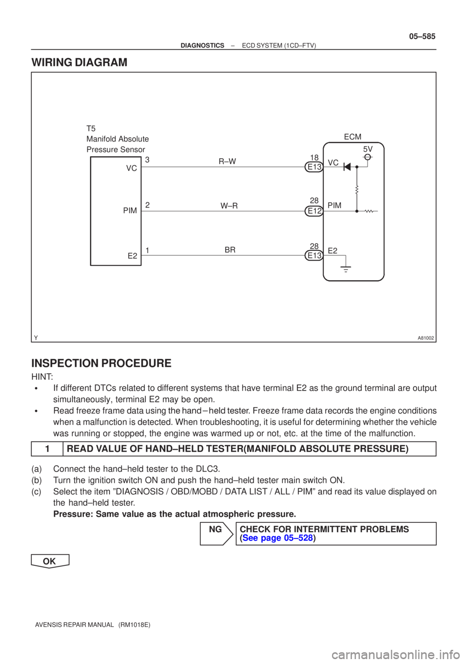
A81002
5V
W±R E13
3
2
1
VC
PIM
E2
T5
Manifold Absolute
Pressure Sensor
ECM
E2
PIM
VC
28 28 18
R±W
BR E12
E13
±
DIAGNOSTICS ECD SYSTEM(1CD±FTV)
05±585
AVENSIS REPAIR MANUAL (RM1018E)
WIRING DIAGRAM
INSPECTION PROCEDURE
HINT:
�If different DTCs related to different systems that have terminal E2 as the ground terminal are output
simultaneously, terminal E2 may be open.
�Read freeze frame data using \f���� ����\b�\f��\f�
� Freeze frame data records the engine conditions
when a malfunction is detected. When troubleshooting, it is useful for d\
etermining whether the vehicle
was running or stopped, the engine was warmed up or not, etc. at the time o\
f the malfunction.
1READ VALUE OF HAND±HELD TESTER(MANIFOLD ABSOLUTE PRESSURE)
(a)Connect the hand±held tester to the DLC3.
(b)Turn the ignition switch ON and push the hand±held tester main switch \
ON.
(c)Select the item ºDIAGNOSIS / OBD/MOBD / DATA LIST / ALL / PIMº and read its value displayed on the hand±held tester.
Pressure: Same value as the actual atmospheric pressure.
NGCHECK FOR INTERMITTENT PROBLEMS(See page 05±528)
OK
Page 671 of 5135

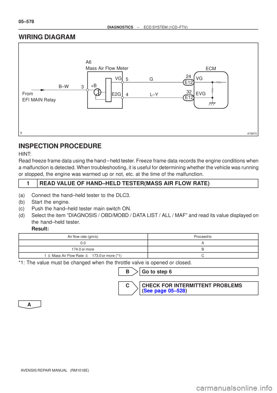
A76970
L±Y
3
4
A6
Mass Air Flow Meter
ECM
5 G
+B VG
E2G
From
EFI MAIN Relay B±W
VG
E12
EVG
24
32
E12
05±578
±
DIAGNOSTICS ECD SYSTEM(1CD±FTV)
AVENSIS REPAIR MANUAL (RM1018E)
WIRING DIAGRAM
INSPECTION PROCEDURE
HINT:
Read freeze frame data using �����\b��������
�� . Freeze frame data records the engine conditions when
a malfunction is detected. When troubleshooting, it is useful for determi\
ning whether the vehicle was running
or stopped, the engine was warmed up or not, etc. at the time of the malfu\
nction.
1READ VALUE OF HAND±HELD TESTER(MASS AIR FLOW RATE)
(a)Connect the hand±held tester to the DLC3.
(b)Start the engine.
(c)Push the hand±held tester main switch ON.
(d)Select the item ºDIAGNOSIS / OBD/MOBD / DATA LIST / ALL / MAFº and read its value displayed on the hand±held tester.
Result:
Air flow rate (gm/s)Proceed to
0.0A
174.0 or moreB
1 � Mass Air Flow Rate �173.0 or more (*1)C
*1: The value must be changed when the throttle valve is opened or closed.
BGo to step 6
CCHECK FOR INTERMITTENT PROBLEMS (See page 05±528)
A