Page 572 of 5135

A81703
From
Speed SensorSkid
Control
ECU4±Pulse
Combination
MeterECM 4±Pulse
A76866
Combination MeterECM
C11V±W
SPD 17
V±W
E10 J/C
18 H
J10
(LHD)J20H
(RHD)H
J10
(LHD)J20H
(RHD)
± DIAGNOSTICSSFI SYSTEM (1AZ±FSE)
05±453
AVENSIS REPAIR MANUAL (RM1018E)
DTC P0500 VEHICLE SPEED SENSOR ºAº
CIRCUIT DESCRIPTION
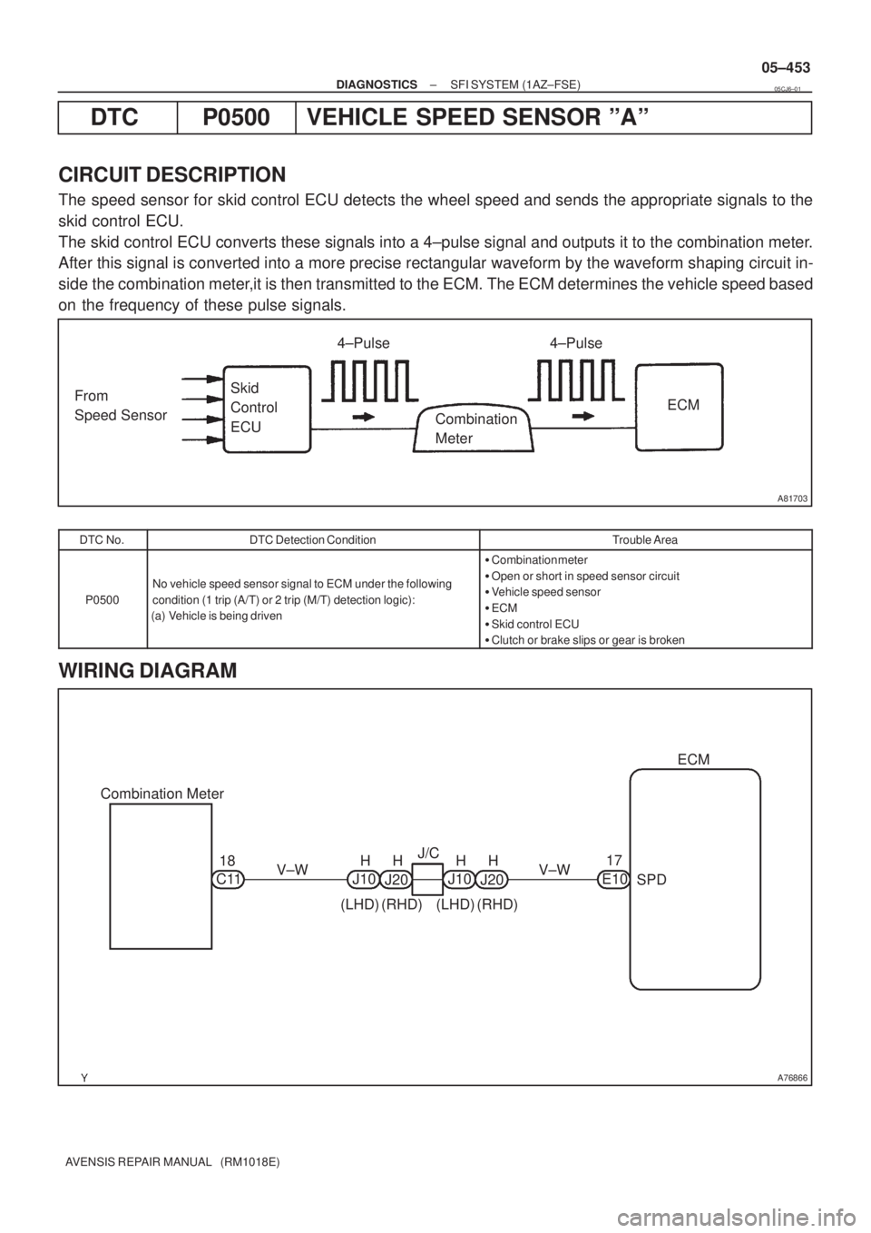
The speed sensor for skid control ECU detects the wheel speed and sends the appropriate signals to the
skid control ECU.
The skid control ECU converts these signals into a 4±pulse signal and outputs it to the combination meter.
After this signal is converted into a more precise rectangular waveform by the waveform shaping circuit in-
side the combination meter,it is then transmitted to the ECM. The ECM determines the vehicle speed based
on the frequency of these pulse signals.
DTC No.DTC Detection ConditionTrouble Area
P0500
No vehicle speed sensor signal to ECM under the following
condition (1 trip (A/T) or 2 trip (M/T) detection logic):
(a) Vehicle is being driven
�Combination meter
�Open or short in speed sensor circuit
�Vehicle speed sensor
�ECM
�Skid control ECU
�Clutch or brake slips or gear is broken
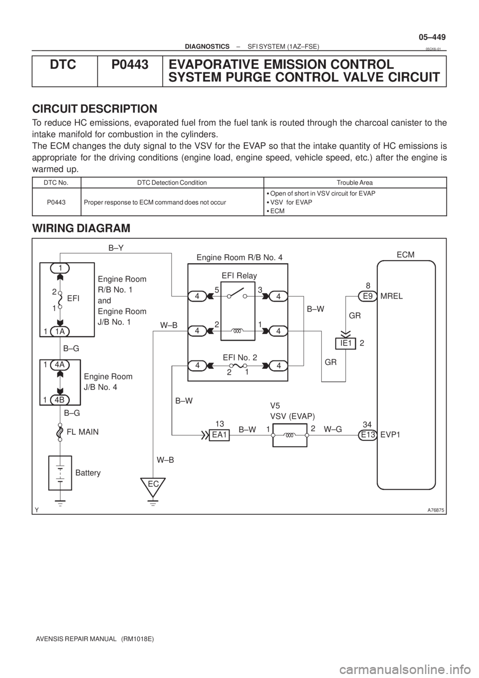
WIRING DIAGRAM
05CJ6±01
Page 574 of 5135

A76875
ECM
EVP1 34
E13 EFI Relay
1 1 23
Engine Room
J/B No. 4B±W
1MREL 8
E9
Battery FL MAIN B±G2 5
GR
V5
VSV (EVAP)
2
W±G EFI No. 2 1
B±G
W±B
ECW±B
4A
14B11AEFI
1B±Y
1
2 4
4
44
4
4
B±W Engine Room
R/B No. 1
and
Engine Room
J/B No. 1Engine Room R/B No. 4
GR
B±W
EA113IE1 2
± DIAGNOSTICSSFI SYSTEM (1AZ±FSE)
05±449
AVENSIS REPAIR MANUAL (RM1018E)
DTC P0443 EVAPORATIVE EMISSION CONTROL
SYSTEM PURGE CONTROL VALVE CIRCUIT
CIRCUIT DESCRIPTION
To reduce HC emissions, evaporated fuel from the fuel tank is routed through the charcoal canister to the
intake manifold for combustion in the cylinders.
The ECM changes the duty signal to the VSV for the EVAP so that the intake quantity of HC emissions is
appropriate for the driving conditions (engine load, engine speed, vehicle speed, etc.) after the engine is
warmed up.
DTC No.DTC Detection ConditionTrouble Area
P0443Proper response to ECM command does not occur
�Open of short in VSV circuit for EVAP
�VSV for EVAP
�ECM
WIRING DIAGRAM
05CK6±01
Page 583 of 5135
A76873
8
IGF1 IGT2 IGT1
IGT3 E13
IGT4 I1
Ignition Coil and
Igniter No. 1
P R±W
IGNW±R IE4
LG±B
ECR±B
L±YE13
E13
E13
E139
1110
24 I2
Ignition Coil and
Igniter No. 2
I3
Ignition Coil and
Igniter No. 3
I4
Ignition Coil and
Igniter No. 4W±R
W±RW±R 3
2
14
1
42
2 3
3
3 1
4
4 1 R±B R±B
R±B R±B R±B B±R
W±B
W±B
W±B
W±BW±B W±BW±B
1
N2
Noise Filter
(Ignition)R±B B±R 1
3 Engine Room R/B No. 1 and
Engine Room J/B No. 1
B±G 1A
2
B±G
FL MAIN
Battery Engine Room
J/B No.4I13
Ignition Switch
6
AM2 IG24
(LHD)IP11
(RHD)
B±R
1
1
1 1 2
2 AM2IG2
1B±R
BB
5144
44DH 2
DL 16
IG2
Relay
4A 1
4B 1Engine
Room
R/B No.4
EA1
8R±B
W±BR±BW±B
EF B±R2ECM
W±R
W±R Driver
Side J/B
± DIAGNOSTICSSFI SYSTEM (1AZ±FSE)
05±441
AVENSIS REPAIR MANUAL (RM1018E)
WIRING DIAGRAM
Page 589 of 5135
A76881
IE4B±R
I13
Ignition SW
AM2
FCECM
1
B±R
6 6 4
2
IB1 Engine Room
R/B No. 1
B±G
FL MAIN
BatteryB±R
ECW±B 1ADHE9 10
IC3
32 51
1
3 5
4B 1AM2
IG2
Relay
B±G
F25
Fuel
Pump 4
5
W±B 10 Engine
Room
R/B No. 4IG2
1
24 4
4 4 4A 1C8
Circuit
Opening
Relay 16 DLIGN B±R
(LHD)IP11
(RHD)
IG2
B±R
Driver
Side J/B
B 1
11
2 2
1
Engine Room
R/B No. 4
BR B±WB±WB±WB±W
L±BG±Y G±YG±Y 05±508
± DIAGNOSTICSSFI SYSTEM (1AZ±FSE)
AVENSIS REPAIR MANUAL (RM1018E)
WIRING DIAGRAM
Page 594 of 5135

A76879
IP1I13
Ignition Switch
IGN Driver Side J/B
E9
E11ECM
Battery FL MAINEFI
No. 1
2
B±G2
118
9
18 4DH
2
E9E9
1 12 31 5
EFI
Relay
D
EFBR GR B±W
DA
J/C 1A
J28IGSW
+B2 MREL
E1
Engine Room
J/B No. 41 4A
4BEngine Room
R/B No. 1 and
Engine Room
J/B No. 1 1EFI AM2
1 211
1 2
B±G6
(RHD) IE4 1 (LHD)
B±R B±R B±R
4 4
4
4
4
4Engine Room
R/B No. 4
Engine
Room
R/B No. 4B±Y
B±W
B±R
ECW±B
B±RB±R B±R
(RHD) (LHD)
D J14 D J28 (RHD)(LHD)
D J14
D J28 D J141
E9 +B (RHD)
(LHD)B±W
B±W (RHD)
(LHD)B±W
J26A
J27E
J8
J/CJ/C
CC
IE12
GR
(LHD) (RHD)IP1 IE42
3
AM2 IG2
05±502
± DIAGNOSTICSSFI SYSTEM (1AZ±FSE)
AVENSIS REPAIR MANUAL (RM1018E)
ECM POWER SOURCE CIRCUIT
CIRCUIT DESCRIPTION
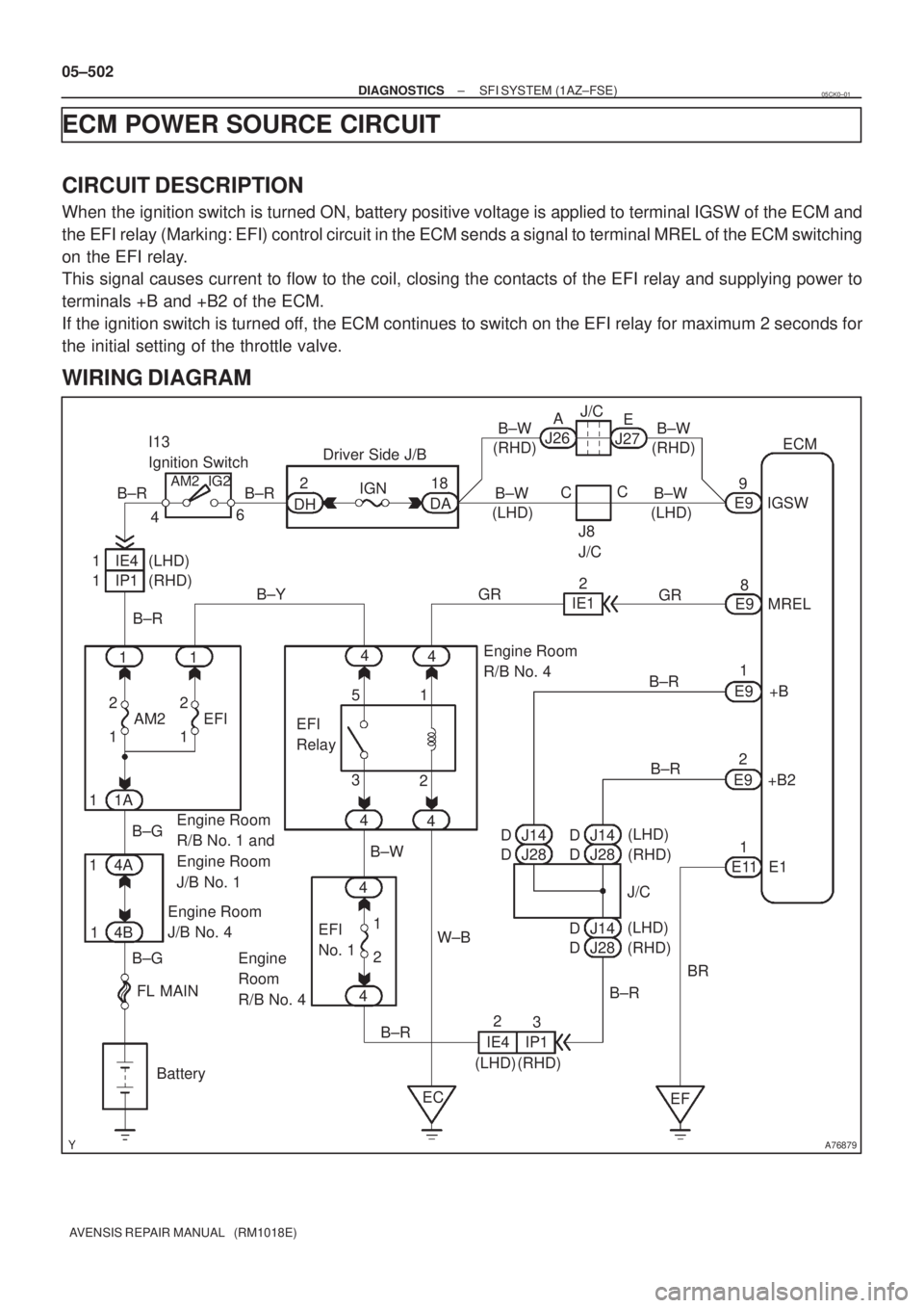
When the ignition switch is turned ON, battery positive voltage is applied to terminal IGSW of the ECM and
the EFI relay (Marking: EFI) control circuit in the ECM sends a signal to terminal MREL of the ECM switching
on the EFI relay.
This signal causes current to flow to the coil, closing the contacts of the EFI relay and supplying power to
terminals +B and +B2 of the ECM.
If the ignition switch is turned off, the ECM continues to switch on the EFI relay for maximum 2 seconds for
the initial setting of the throttle valve.
WIRING DIAGRAM
05CK0±01
Page 602 of 5135
A76878
A20
Accel Position
Sensor
VCP16 (LHD)
E926ECM
VCPA B
4 (RHD)
(LHD)B
(LHD) 5
IG2
B
(RHD)
VPA15 (LHD)
E922
VPA G
5 (RHD)
(LHD)G
(LHD) 6
IG2
G
(RHD)
EP13 (LHD)
E928
EPA Y
1 (RHD)
(LHD)Y
(LHD) 1
IG2
Y
(RHD)
VCP24 (LHD)
E927
VCP2 B
6 (RHD)
(LHD)B
(LHD) 7
IG2
B
(RHD)
VPA22 (LHD)
E923
VPA2 W
2 (RHD)
(LHD)W
(LHD) 2
IG2
W
(RHD)
EP21 (LHD)
E929
EPA2 Y
3 (RHD)
(LHD)Y
(LHD) 3
IG2
Y
(RHD)
± DIAGNOSTICSSFI SYSTEM (1AZ±FSE)
05±495
AVENSIS REPAIR MANUAL (RM1018E)
WIRING DIAGRAM
INSPECTION PROCEDURE
HINT:
Read freeze frame data using the hand±held tester. Freeze frame data records the engine conditions when
a malfunction is detected. When troubleshooting, it is useful for determining whether the vehicle was running
or stopped, the engine was warmed up or not, the air±fuel ratio was lean or rich, etc. at the time of the mal-
function.
Page 606 of 5135

05±490
±
DIAGNOSTICS SFI SYSTEM(1AZ±FSE)
AVENSIS REPAIR MANUAL (RM1018E)
DTCP2119THROTTLE ACTUATOR CONTROL THROTTLE BODY RANGE/PERFORMANCE
CIRCUIT DESCRIPTION
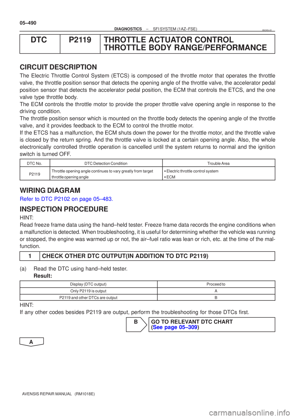
The Electric Throttle Control System (ETCS) is composed of the throttle m\
otor that operates the throttle
valve, the throttle position sensor that detects the opening angle of the throttle valve, the accelerator pedal
position sensor that detects the accelerator pedal position, the ECM that contro\
ls the ETCS, and the one
valve type throttle body.
The ECM controls the throttle motor to provide the proper throttle valve\
opening angle in response to the
driving condition.
The throttle position sensor which is mounted on the throttle body detects \
the opening angle of the throttle
valve, and it provides feedback to the ECM to control the throttle motor.
If the ETCS has a malfunction, the ECM shuts down the power for the throttle motor, and the throttle valve
is closed by the return spring. And the throttle valve is locked at a ce\
rtain opening angle. Also, the whole
electronically controlled throttle operation is cancelled until the system returns to normal and the ignition
switch is turned OFF.
DTC No.DTC Detection ConditionTrouble Area
P2119Throttle opening angle continues to vary greatly from target
throttle opening angle�Electric throttle control system
� ECM
WIRING DIAGRAM
Refer to DTC P2102 on page 05±483.
INSPECTION PROCEDURE
HINT:
Read freeze frame data using the hand±held tester. Freeze frame data records the engine conditions when
a malfunction is detected. When troubleshooting, it is useful for determi\
ning whether the vehicle was running
or stopped, the engine was warmed up or not, the air±fuel ratio was lea\
n or rich, etc. at the time of the mal-
function.
1CHECK OTHER DTC OUTPUT(IN ADDITION TO DTC P2119)
(a)Read the DTC using hand±held tester.
Result:
Display (DTC output)Proceed to
Only P2119 is outputA
P2119 and other DTCs are outputB
HINT:
If any other codes besides P2119 are output, perform the troubleshooting for those DTCs first.
BGO TO RELEVANT DTC CHART (See page 05±309)
A
05CKS±01
Page 608 of 5135
A76877
ECM
+BM
FL MAINTHROTTLE Engine Room J/B No. 1 and
Engine Room R/B No. 1
E10
IE2 1A 4B15
2 Engine Room J/B No. 4
6
B±G
Battery4A1
B±G
1 1
1G±R G±Y
± DIAGNOSTICSSFI SYSTEM (1AZ±FSE)
05±487
AVENSIS REPAIR MANUAL (RM1018E)
DTC P2118 THROTTLE ACTUATOR CONTROL MOTOR
CURRENT RANGE/PERFORMANCE
CIRCUIT DESCRIPTION
If this DTC is detected, the ECM shuts down the power for the throttle motor, and the throttle valve is closed
by the return spring. And the throttle valve is locked at a certain opening angle. Also, the whole electronically
controlled throttle operation is cancelled until the system returns to normal and the ignition switch is turned
OFF.
HINT:
This electrical throttle control system (ETCS) does not use the throttle cable.
DTC No.DTC Detection ConditionTrouble Area
P2118Open in ETCS power source circuit�Open in ETCS power source circuit
�ECM
WIRING DIAGRAM
05CKR±01