Page 839 of 5135
F45135
B±R
DH DA18 2Driver Side J/B
IGNWA S222
IE117 9
B±W
C11 C10Combination Meter
ABSSkid Control ECU
with Actuator
R±Y R±Y 22
17
C10
AM2
4B 4A11IG2
A 1
2 AM2
3
IK 1A
Engine Room R/B No.3 Engine Room R/B No.1 & Engine Room J/B No.1
1
3 Engine Room J/B No.41
IO ILJ15
J/C
Battery
*1: Gasoline
*2: 1CD±FTV
*3: LHD
*4: RHD(*3) (*4) (*3) (*4)B±W CA CA
J8 J26 J8 J26J/C
B±R
IE4 IP111
(*3) (*4) B±R
B (*2)B±G (*1)
B (*2)
FL MAINB±G (*1)
W±B (*3 *2)
W±B (*3 *1)A A
AAJ17
J/C
J16
J/C W±B
(*3) W±B (*4) W±B (*4)
I13
Ignition SW
46 05±742
± DIAGNOSTICSABS WITH EBD SYSTEM
AVENSIS REPAIR MANUAL (RM1018E)
WIRING DIAGRAM
Page 842 of 5135
F45148
IK IJ Battery
*1: Gasoline
*2: 1CD±FTV
*3: LHD
*4: RHDIL IOEA
S2
W±B W±B W±B W±B
(*4)
W±B (*3 *1)
W±B (*3 *2)
AA A A A J15
J/CJ17 J/C
J16 J/C
6 S210
GND2
GND1 ALT
4D
4B4A1
1
1
B±G
(*1)
1 21 21 2 123 5
ALTAM2
B±R
IE4 IP111
(*3) (*4)
1
ED1
33
3B±G (*1)
1A 1
Engine Room J/B No.4B (*2)
B±R
B±L (*2) W (*2)
FL MAIN
B (*2) B±G (*1)Engine Room R/B No.3 Engine Room R/B No.1 & Engine Room J/B No.1 G±Y B±R
B (*2)
1 3
6 4
AM2 AM1
IG1
IG2 I13 Ignition SW
G±RB±R
W±B
1
DH DA DB DH DA
DN
DH51 18 2
18
9 IG1 RelayDriver Side J/B
IGN
ECU±IG
AM1J10
(*3)G
J20C
(*4)J/C
J10
(*3)G
J20C
(*4)R±WR±W
IE1 22IG1 WA S2
S2 18 22
IE117 9
17 (*3) (*4) (*3) (*4)
1 B±W CA CA
J8 J26 J8 J26 C11 C10
C10 Combination Meter
ABSSkid Control ECU
with Actuator
R±Y R±Y 22 J/C
1
W±B (*4)
W±B (*3)
R±W
B±W
05±738
± DIAGNOSTICSABS WITH EBD SYSTEM
AVENSIS REPAIR MANUAL (RM1018E)
WIRING DIAGRAM
Page 845 of 5135
F45132
Battery FL MAINSkid Control ECU
with Actuator
B±G (*1) L (*1)
1 ALT ABS Engine Room R/B No.4 & Engine Room J/B No.4
1
4B
W±BS2
S21 2
+BM
12
1 2
GND1 GND2
S24
W±BW±B
*1: Gasoline
*2: 1CD±FTVEA4
L (*2)
W (*2)
2 12 33 11B1ABS ALT Engine Room R/B No.3Engine Room R/B No.1 &
Engine Room J/B No.1
B (*2)
B±G (*1)
± DIAGNOSTICSABS WITH EBD SYSTEM
05±735
AVENSIS REPAIR MANUAL (RM1018E)
DTC C1350/51 PUMP MOTOR IS LOCKED/OPEN CIRCUIT
IN PUMP MOTOR GROUND
CIRCUIT DESCRIPTION
DTC No.DTC Detecting ConditionTrouble Area
C1350/51
When any of the following 1 through 3 is detected.
1. No motor voltage supply after skid control ECU starts
the motor relay.
2. A high level of motor voltage when skid control ECU
does not start the motor relay.
3. The pump motor voltage is high level for a certain time
after the motor relay has elapsed.
Brake actuator pump motor
WIRING DIAGRAM
05C5B±01
Page 850 of 5135

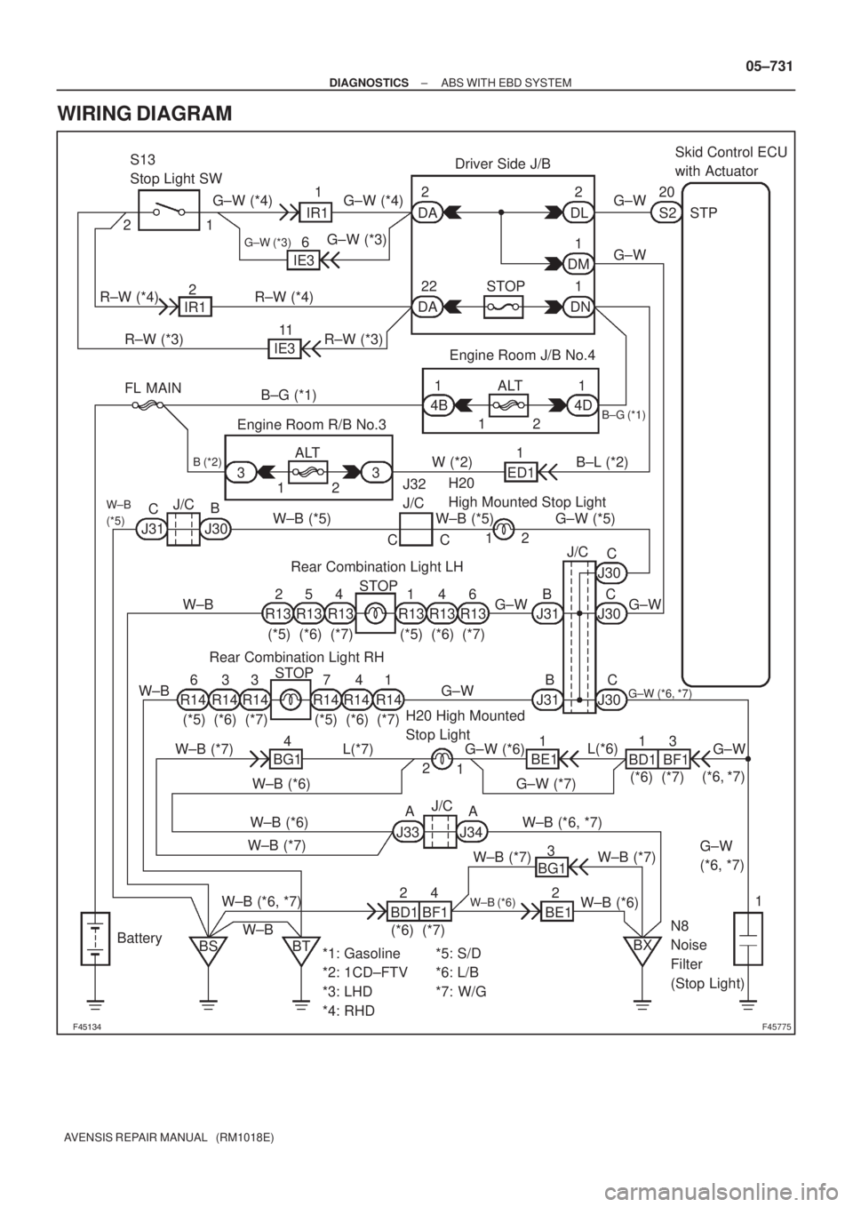
������F45775
Engine Room J/B No.4
ALT 1
4B1
4D B±G (*1)
B±L (*2) FL MAINS2 20
IR1Skid Control ECU
with Actuator
DA
DA DNDMDL 1
1 2
1
1 22
22 STOPDriver Side J/B
G±W (*4) G±W (*4)
G±W (*3)
G±W (*3)6
IE3
IE3 IR12
11
R±W (*3) R±W (*4) R±W (*4)
R±W (*3) S13
Stop Light SW
G±W
G±W
B±G (*1)
STP
123 ALT Engine Room R/B No.3
W (*2)
ED11 12
J/C
J30B
(*5) (*6) (*7) (*5) (*6) (*7)
(*5) (*6) (*7) (*5) (*6) (*7)STOP
STOP J31CJ32
J/C
B (*2)
W±B (*5) G±W (*5) W±B (*5)
W±B
W±B
W±B
(*5)
CC2 1
R13
R14 R14 R14 R14 R14 R14R13 R13 R13 R13 R13J30
J30
J30 J31
J31 21
1 54 64
4 7 3
3 3 6
G±WJ/C
C
C
C B B
G±W G±W
G±W (*6, *7)
BG1Rear Combination Light LHH20
High Mounted Stop Light
N8
Noise
Filter
(Stop Light) Rear Combination Light RH
H20 High Mounted
Stop Light
W±B (*7)
W±B (*7)G±W (*7)
W±B (*7) W±B (*7) W±B (*6)W±B (*6)G±W (*6)
W±B (*6, *7)
W±B (*6, *7)
W±B
(*6) (*7)W±B (*6)
W±B (*6)
J33 J34AAJ/C1 2BE1
BD1 BF113
G±W L(*6)
L(*7)
BD1 BF1(*6) (*7)(*6, *7)
G±W
(*6, *7)
1
BX BE1 BG1 41
2 3
24
BT BS Battery
*1: Gasoline
*2: 1CD±FTV
*3: LHD
*4: RHD*5: S/D
*6: L/B
*7: W/G
± DIAGNOSTICSABS WITH EBD SYSTEM
05±731
AVENSIS REPAIR MANUAL (RM1018E)
WIRING DIAGRAM
Page 854 of 5135
F45132
Battery
FL MAIN Skid Control ECU
with Actuator
B±G (*1)L (*1) 1
ALT
Engine Room R/B No.4 & Engine Room J/B No.4
1
4B
W±BS1
S1 10
9
+BM
12
1
2
GND1 GND2
S1 6
W±B W±B
*1: 1AZ±FSE
*2: 1CD±FTV EA4
L (*2)
W (*2)
2
12
331
1B1
VSC
ALT
Engine Room R/B No.3
Engine Room R/B No.1 &
Engine Room J/B No.1
B (*2)
B±G (*1) VSC
05±806
±
DIAGNOSTICS ABS WITH EBD & BA & TRC & VSC SYSTEM
AVENSIS REPAIR MANUAL (RM1018E)
WIRING DIAGRAM
INSPECTION PROCEDURE
1RECONFIRM DTC
(a)Check if other DTCs are detected (See page 05±756). YES REPAIR CIRCUIT INDICATED BY OUTPUTCODE
NO
REPLACE ABS & TRACTION ACTUATOR ASSY(See page 32±57)
Page 856 of 5135
F45142
Skid Control ECU
with Actuator
SS2
SS1
YGND
YIGA S1 S1 S1 S129
13
16
30
IE83 10
W±G
W±L IE8
W±L J18
J/C
W±G
W±L
W±G
W±L GND
CANL
CANHUBAT
GND CAN
HIGH
12V CAN
LOWB
W (Shielded)
B
W (Shielded)
B
W
(Shielded)
B
W
(Shielded)
B W W±B
W±B (Shielded)1 75
6 4 2 1
3 J6C
B C
B
A
J15
J/C
IK J7E D BD
B
A A B D BJ/C
1
2
9 IE8
J6 J6 J6
J6 J6 J7
J7
J7IE8
IE8
Y1
YAW Rate Sensor
S12
Steering Sensor LHD:
W±G
C
B 05±802
± DIAGNOSTICSABS WITH EBD & BA & TRC & VSC SYSTEM
AVENSIS REPAIR MANUAL (RM1018E)
WIRING DIAGRAM
Page 859 of 5135

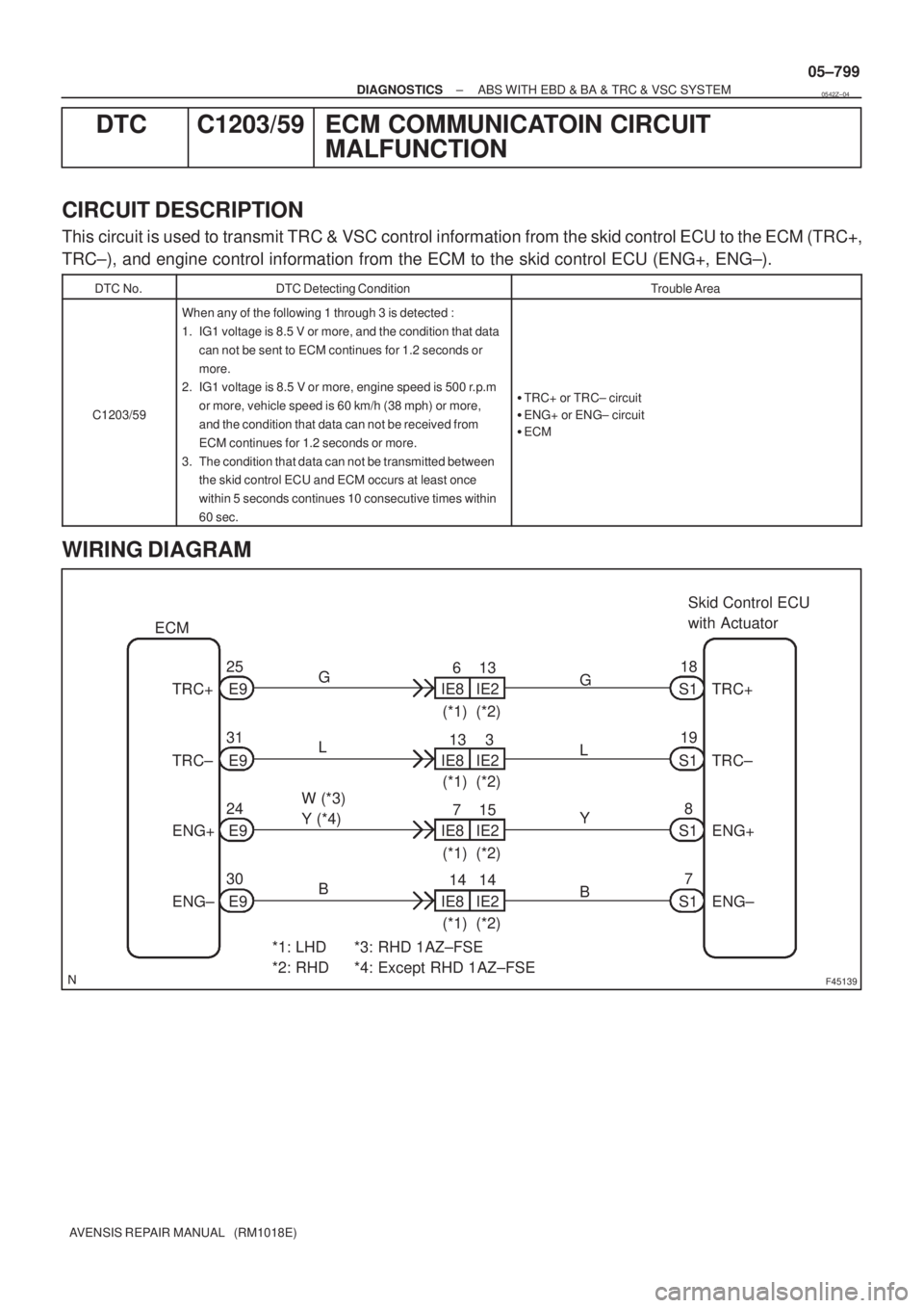
F45139
Skid Control ECU
with Actuator
S118
*1: LHD
*2: RHDG
TRC+ E925
IE86
IE213
(*1) (*2) ECM
E9 31
E9 24
E9 30 TRC±
ENG+
ENG±
*3: RHD 1AZ±FSE
*4: Except RHD 1AZ±FSEIE813
IE23
(*1) (*2)
IE87
IE215
(*1) (*2)
IE814
IE214
(*1) (*2) L
W (*3)
Y (*4)
BG
L
Y
BS1
S1
S17 8 19TRC+
TRC±
ENG+
ENG±
± DIAGNOSTICSABS WITH EBD & BA & TRC & VSC SYSTEM
05±799
AVENSIS REPAIR MANUAL (RM1018E)
DTC C1203/59 ECM COMMUNICATOIN CIRCUIT
MALFUNCTION
CIRCUIT DESCRIPTION
This circuit is used to transmit TRC & VSC control information from the skid control ECU to the ECM (TRC+,
TRC±), and engine control information from the ECM to the skid control ECU (ENG+, ENG±).
DTC No.DTC Detecting ConditionTrouble Area
C1203/59
When any of the following 1 through 3 is detected :
1. IG1 voltage is 8.5 V or more, and the condition that data
can not be sent to ECM continues for 1.2 seconds or
more.
2. IG1 voltage is 8.5 V or more, engine speed is 500 r.p.m
or more, vehicle speed is 60 km/h (38 mph) or more,
and the condition that data can not be received from
ECM continues for 1.2 seconds or more.
3. The condition that data can not be transmitted between
the skid control ECU and ECM occurs at least once
within 5 seconds continues 10 consecutive times within
60 sec.
�TRC+ or TRC± circuit
�ENG+ or ENG± circuit
�ECM
WIRING DIAGRAM
0542Z±04
Page 861 of 5135
F45138
Skid Control ECU
with ActuatorNEO
S1 32
Y±B
*1: LHD
*2: RHD Y±B
NEOE9 17
IE85
IE113
(*1)(*2)
ECM
±
DIAGNOSTICS ABS WITH EBD & BA & TRC & VSC SYSTEM
05±797
AVENSIS REPAIR MANUAL (RM1018E)
DTCC1204/44NE SIGNAL CIRCUIT
CIRCUIT DESCRIPTION
The skid control ECU receives engine revolution speed signals (NE signals)\
from the ECM.
DTC No.DTC Detecting ConditionTrouble Area
C1202/44
At vehicle speed of 30 km/h (19 mph) or more, when data
received from the ECM is in normal condition, engine revo-
lution signal > 0 rpm continues for 5 seconds or more.�NEO circuit
� ECM
� Skid control ECU
WIRING DIAGRAM
INSPECTION PROCEDURE
1CHECK HARNESS AND CONNECTOR(SKID CONTROL ECU ± ECM)
(a)Check for an open or short circuit in harness and connector between terminal \
NEO of the skid control
ECU and ECM (See page 01±32).
NG REPAIR OR REPLACE HARNESS ORCONNECTOR
OK
05432±04