Page 4675 of 5135
A87967
Upward90_
Clamp
Bolt
Turbocharger Side:
Air Hose No. 2 Side:
Front 90
_ Clamp Bolt
20.4_
14
−134
−
ENGINE MECHANICAL PARTIAL ENGINE ASSY (1CD −FTV)(From September,
2003)
AVENSIS Supplement (RM1045E)
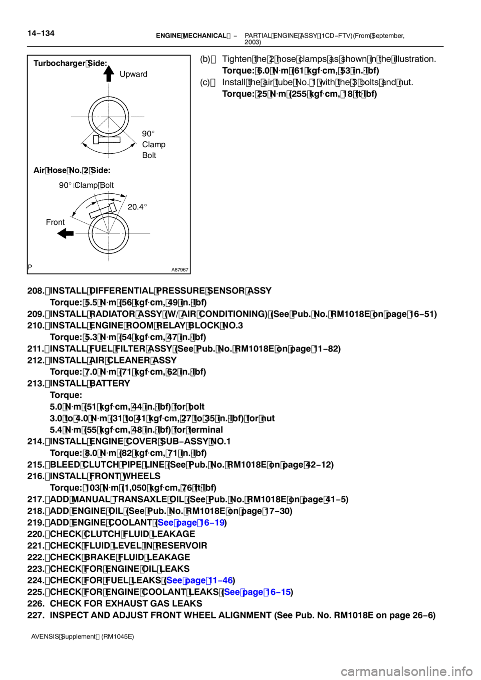
(b) Tighten the 2 hose clamps as shown in the illustration. Torque: 6.0 N �m (61 kgf �cm, 53 in. �lbf)
(c) Install the air tube No. 1 with the 3 bolts and nut. Torque: 25 N �m (255 kgf �cm, 18 ft �lbf)
208. INSTALL DIFFERENTIAL PRESSURE SENSOR ASSY Torque: 5.5 N �m (56 kgf �cm, 49 in. �lbf)
209. INSTALL RADIATOR ASSY (W/ AIR CONDITIONING) (See Pub. No. RM1018E on page 16 −51)
210. INSTALL ENGINE ROOM RELAY BLOCK NO.3
Torque: 5.3 N �m (54 kgf �cm, 47 in. �lbf)
211. INSTALL FUEL FILTER ASSY (See Pub. No. RM1018E on page 11 −82)
212. INSTALL AIR CLEANER ASSY Torque: 7.0 N �m (71 kgf �cm, 62 in. �lbf)
213. INSTALL BATTERY Torque:
5.0 N�m (51 kgf �cm, 44 in. �lbf) for bolt
3.0 to 4.0 N �m (31 to 41 kgf �cm, 27 to 35 in. �lbf) for nut
5.4 N �m (55 kgf �cm, 48 in. �lbf) for terminal
214. INSTALL ENGINE COVER SUB −ASSY NO.1
Torque: 8.0 N �m (82 kgf �cm, 71 in. �lbf)
215. BLEED CLUTCH PIPE LINE (See Pub. No. RM1018E on page 42 −12)
216. INSTALL FRONT WHEELS
Torque: 103 N �m (1,050 kgf �cm, 76 ft �lbf)
217. ADD MANUAL TRANSAXLE OIL (See Pub. No. RM1018E on page 41 −5)
218. ADD ENGINE OIL (See Pub. No. RM1018E on page 17 −30)
219. ADD ENGINE COOLANT (See page 16 −19)
220. CHECK CLUTCH FLUID LEAKAGE
221. CHECK FLUID LEVEL IN RESERVOIR
222. CHECK BRAKE FLUID LEAKAGE
223. CHECK FOR ENGINE OIL LEAKS
224. CHECK FOR FUEL LEAKS (See page 11 −46)
225. CHECK FOR ENGINE COOLANT LEAKS (See page 16 −15)
226. CHECK FOR EXHAUST GAS LEAKS
227. INSPECT AND ADJUST FRONT WHEEL ALIGNMENT (See Pub. No. RM1018E on page 26 −6)
Page 4695 of 5135
14−84
−
ENGINE MECHANICAL CYLINDER HEAD GASKET (2AZ −FSE)
AVENSIS Supplement (RM1045E)
94. INSTALL FUEL PIPE SUB −ASSY NO.1 (See page 11 −24)
SST 09023 −12900
95. INSTALL FUEL TUBE SUB −ASSY (See page 11 −24)
96. INSTALL FUEL PRESSURE PULSATION DAMPER ASSY (See page 11 −24)
97. INSTALL ENGINE COVER SUB −ASSY NO.1
Torque: 7.0 N �m (71 kgf �cm, 62 in. �lbf)
98. INSTALL VANE PUMP ASSY Torque: 37 N �m (377 kgf �cm, 27 ft �lbf)
99. INSTALL EXHAUST PIPE ASSY FRONT (See page 15 −2)
100. INSTALL GENERATOR ASSY (See page 19 −8)
101. INSTALL FAN AND GENERATOR V BELT (See page 14 −5)
SST 09249 −63010
102. ADD COOLANT (See page 16 −7)
103. ADD ENGINE OIL (See page 17 −6)
104. CHECK FOR ENGINE COOLANT LEAKS (See page 16 −1)
105. CHECK FOR ENGINE OIL LEAKS
106. CHECK FOR FUEL LEAKS (See page 11 −4)
107. INSTALL FRONT WHEEL RH Torque: 103 N �m (1,050 kgf �cm, 76 ft �lbf)
108. ADD POWER STEERING FLUID (See Pub. No. RM1018E on page 51 −4)
109. BLEED POWER STEERING FLUID (See Pub. No. RM1018E on page 51 −4)
110. CHECK POWER STEERING FULUID LEVEL IN RESERVOIR
(See Pub. No. RM1018E on page 51 −4)
111. CHECK FUNCTION OF THROTTLE BODY
Page 4704 of 5135
A93078
12 (122, 9.0)
60 (607, 44)
N·m (kgf·cm, ft·lbf)
: Specified torque
zNon−reusable partV−ribbed Belt
Tensioner Assy
Oil Level Gage
Sub−assy
Exhaust Manifold Insulator
zGasket
37 (378, 27)
x5
Manifold Stay No. 1
44 (449, 32)
Exhaust Manifold Converter Sub−assy
Manifold Stay No. 2
44 (449, 32)
zO−ring
Oil Level Gage Guide
12 (122, 9.0)
12 (122, 9.0)
− ENGINE MECHANICALCYLINDER HEAD GASKET (2AZ−FSE)
14−77
AVENSIS Supplement (RM1045E)
Page 4715 of 5135
A93078
A93080
12 (122, 9.0)
N·m (kgf·cm, ft·lbf)
: Specified torque
zNon−reusable partOil Level Gage
Sub−assy
Exhaust Manifold Insulator
zGasket
37 (378, 27)
x5
Manifold Stay No. 1
44 (449, 32)
Exhaust Manifold Converter Sub−assy
Manifold Stay No. 2
44 (449, 32)
zO−ring
Oil Level Gage Guide
12 (122, 9.0)
12 (122, 9.0)
14−20
− ENGINE MECHANICALPARTIAL ENGINE ASSY (2AZ−FSE)
AVENSIS Supplement (RM1045E)
Page 4725 of 5135
A84387
2to7mm
(0.0787 to
0.2756 in.) 0to5mm
(0 to 0.1969 in.) 0to2mm
(0 to 0.0787 in.) *1*2
*2: *1:
Turbocharger Side
Intercooler Side
A93662
Turbocharger Side:
Intercooler Side: Upward
90_
Cl a m p
Bolt
90_
Cl a m p
Bolt
Front
−
INTAKE TURBOCHARGER SUB −ASSY (1CD −FTV)(From
September, 2003)13 −19
AVENSIS Supplement (RM1045E)
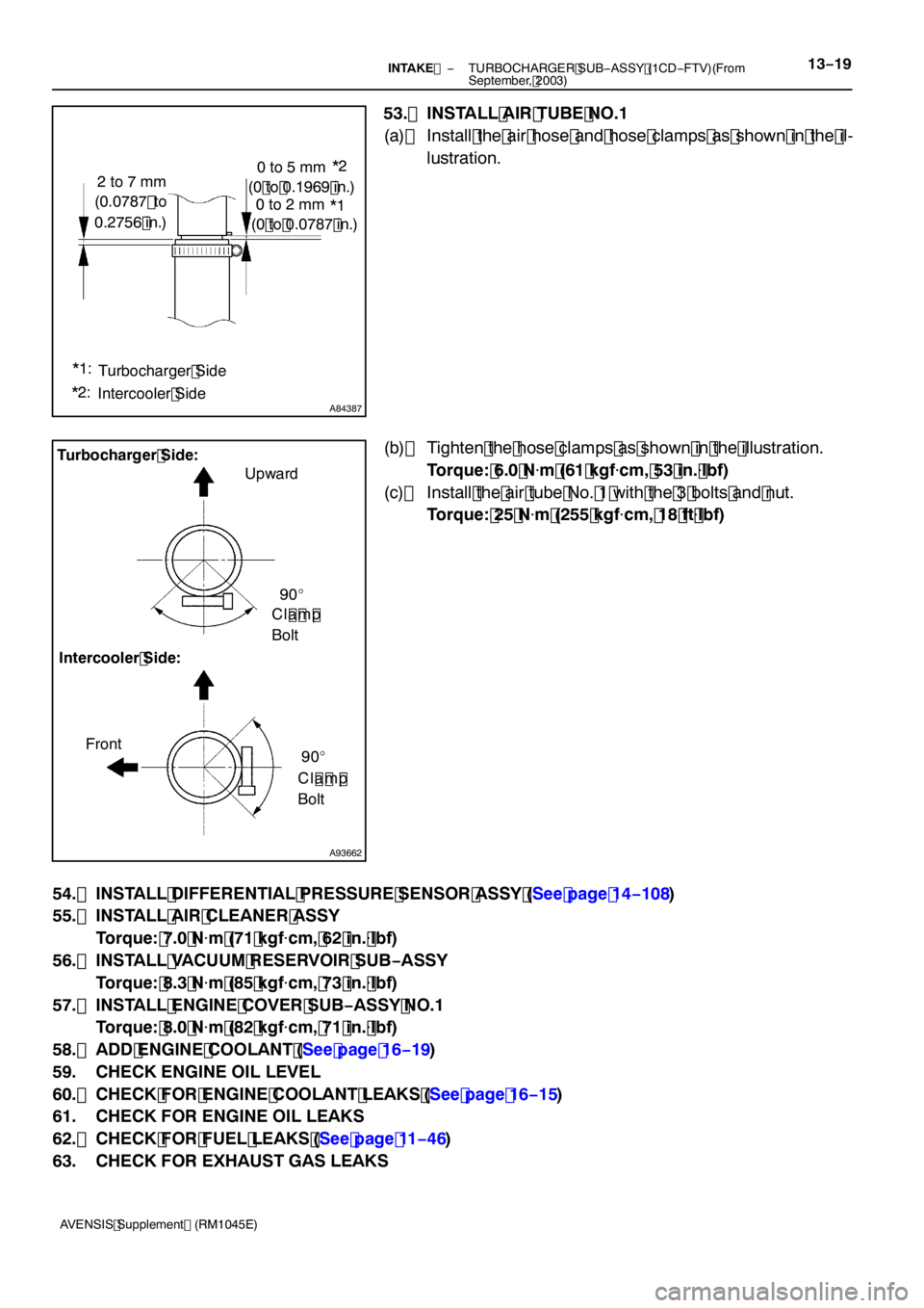
53. INSTALL AIR TUBE NO.1
(a) Install the air hose and hose clamps as shown in the il-
lustration.
(b) Tighten the hose clamps as shown in the illustration. Torque: 6.0 N �m (61 kgf �cm, 53 in. �lbf)
(c) Install the air tube No. 1 with the 3 bolts and nut. Torque: 25 N �m (255 kgf �cm, 18 ft �lbf)
54. INSTALL DIFFERENTIAL PRESSURE SENSOR ASSY (See page 14 −108)
55. INSTALL AIR CLEANER ASSY
Torque: 7.0 N �m (71 kgf �cm, 62 in. �lbf)
56. INSTALL VACUUM RESERVOIR SUB −ASSY
Torque: 8.3 N �m (85 kgf �cm, 73 in. �lbf)
57. INSTALL ENGINE COVER SUB −ASSY NO.1
Torque: 8.0 N �m (82 kgf �cm, 71 in. �lbf)
58. ADD ENGINE COOLANT (See page 16 −19)
59. CHECK ENGINE OIL LEVEL
60. CHECK FOR ENGINE COOLANT LEAKS (See page 16 −15)
61. CHECK FOR ENGINE OIL LEAKS
62. CHECK FOR FUEL LEAKS (See page 11 −46)
63. CHECK FOR EXHAUST GAS LEAKS
Page 4733 of 5135

C83155
F40218
SST
C91598
C86265
30−6
− DRIVE SHAFT / PROPELLER SHAFTFRONT DRIVE SHAFT (2AZ−FSE)
AVENSIS Supplement (RM1045E)
11. REMOVE FRONT DRIVE SHAFT ASSY RH (RH DRIVE
SHAFT)
(a) Remove the 2 bolts and pull out the drive shaft together
with the center bearing bracket.
(b) Remove the drive shaft from the transaxle.
NOTICE:
SBe careful not to damage the oil seal, boot and dust
cover.
SBe careful not to drop the drive shaft assy.
12. FIX FRONT AXLE HUB LH BEARING
NOTICE:
The hub bearing may become damaged if subjected to the
vehicle weight. For example, moving the vehicle with the
drive shaft removed.
Therefore, if it is absolutely necessary to place the vehicle
weight on the hub bearing, first support it with SST.
SST 09608−16042 (09608−02021, 09608−02041)
13. INSPECT FRONT DRIVE SHAFT ASSY LH
(a) Check that there is no excessive play in the radial direc-
tion of the outboard joint.
(b) Check that the inboard joint slides smoothly in the thrust
direction.
(c) Check that there is no excessive play in the radial direc-
tion of the inboard joint.
(d) Check the boots for damage.
NOTICE:
Keep the drive shaft assy level during inspection.
14. REMOVE FRONT AXLE INBOARD JOINT BOOT
CLAMP
(a) Using pliers, remove the inboard joint boot LH No.2 clamp
as shown in the illustration.
(b) Remove the inboard joint boot LH clamp ifollwng the
same procedure as for the inboard joint boot LH No.2
clamp.
15. REMOVE FR AXLE INBOARD JOINT BOOT
(a) Remove the inboard joint boot from the inboard joint assy LH.
Page 4749 of 5135
B08016
O−ring
A85926
A56695
A79175
SST SST
17
−12
−
LUBRICATION OIL PUMP ASSY (1CD −FTV)(From September, 2003)
AVENSIS Supplement (RM1045E)
26. REMOVE FLOOR PANEL BRACE FRONT (See page 15 −6)
27. REMOVE EXHAUST PIPE ASSY FRONT (See page 15 −6)
28. REMOVE GENERATOR ASSY (See Pub. No. RM1018E on page 19 −29)
29. REMOVE TIMING BELT IDLER SUB −ASSY NO.1 (See page 16 −21)
30. REMOVE V −RIBBED BELT TENSIONER ASSY (See page 14 −108)
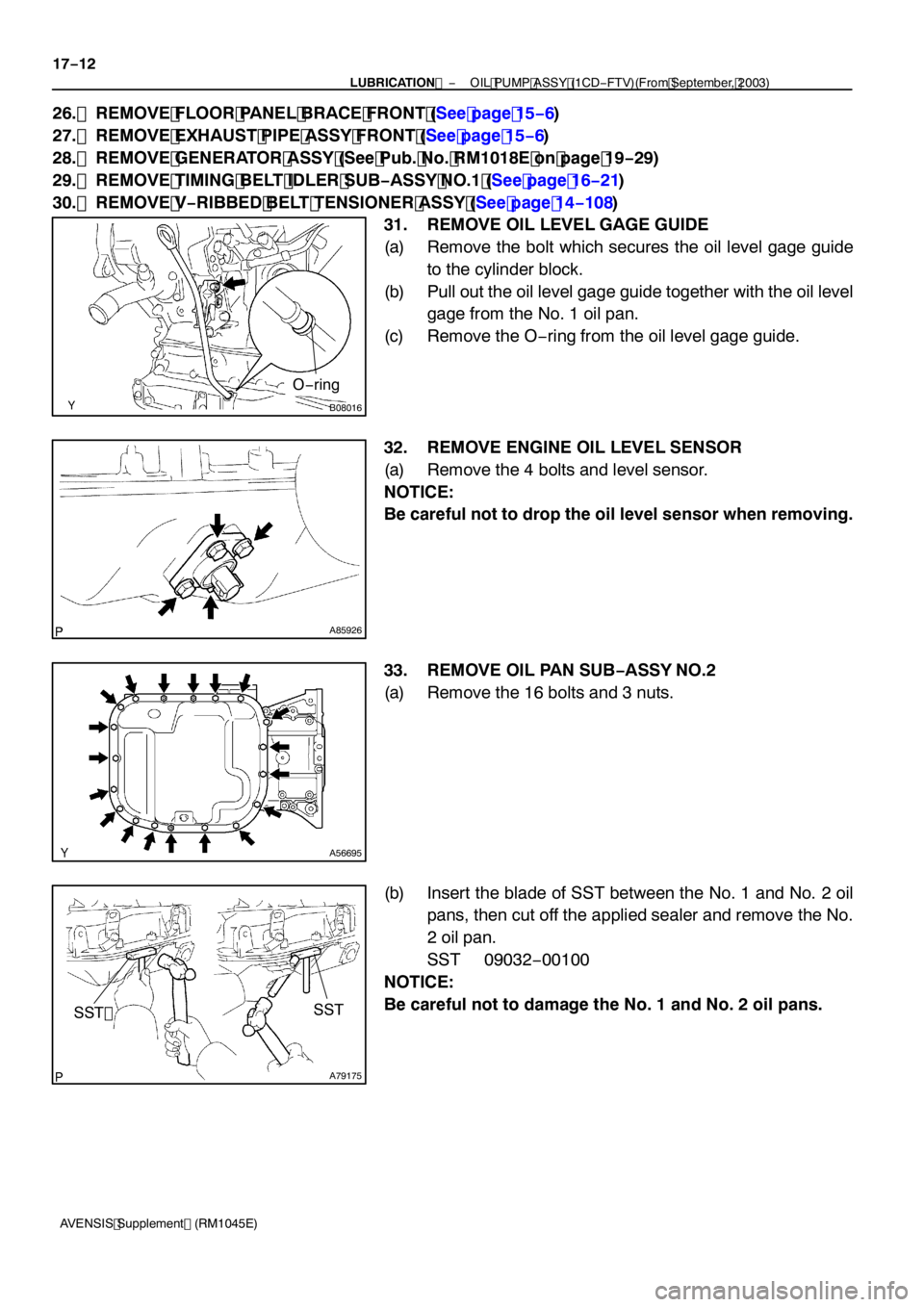
31. REMOVE OIL LEVEL GAGE GUIDE
(a) Remove the bolt which secures the oil level gage guide to the cylinder block.
(b) Pull out the oil level gage guide together with the oil level gage from the No. 1 oil pan.
(c) Remove the O −ring from the oil level gage guide.
32. REMOVE ENGINE OIL LEVEL SENSOR
(a) Remove the 4 bolts and level sensor.
NOTICE:
Be careful not to drop the oil level sensor when removing.
33. REMOVE OIL PAN SUB −ASSY NO.2
(a) Remove the 16 bolts and 3 nuts.
(b) Insert the blade of SST between the No. 1 and No. 2 oil pans, then cut off the applied sealer and remove the No.
2 oil pan.
SST 09032 −00100
NOTICE:
Be careful not to damage the No. 1 and No. 2 oil pans.
Page 4754 of 5135
A56704
Seal Width
4to7mm
(0.16 to 0.28 in.)
A
A
B
B
B08016
New O −ring
SST
A09583
Inward
Angle Sensor
−
LUBRICATION OIL PUMP ASSY (1CD −FTV)(From September, 2003)
17 −17
AVENSIS Supplement (RM1045E)
(3) Using a non −residue solvent, clean both the sealing
surfaces.
NOTICE:
Do not use a solvent. It will affect the painted surfaces.
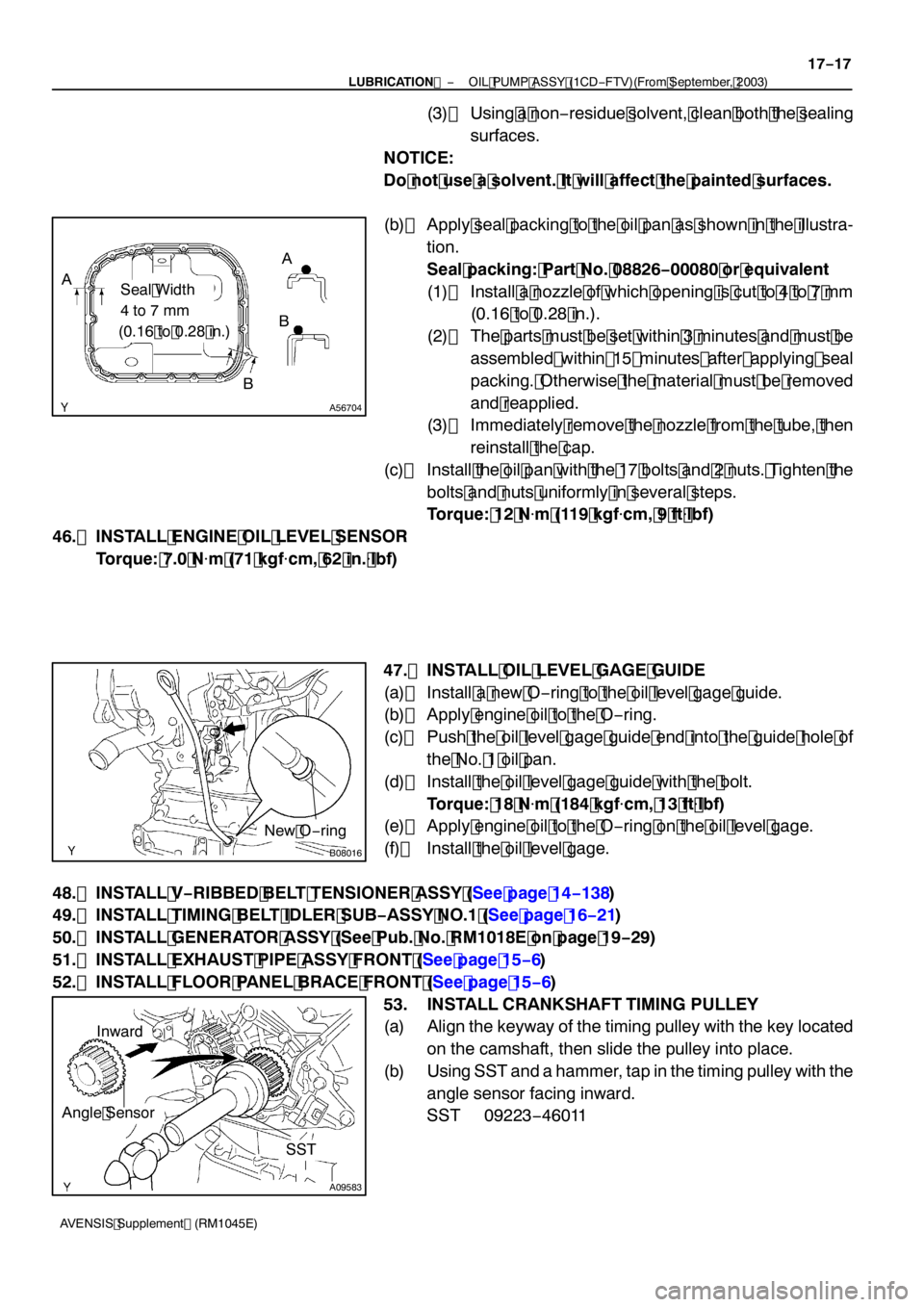
(b) Apply seal packing to the oil pan as shown in the illustra- tion.
Seal packing: Part No. 08826 −00080 or equivalent
(1) Install a nozzle of which opening is cut to 4 to 7 mm (0.16 to 0.28 in.).
(2) The parts must be set within 3 minutes and must be assembled within 15 minutes after applying seal
packing. Otherwise the material must be removed
and reapplied.
(3) Immediately remove the nozzle from the tube, then
reinstall the cap.
(c) Install the oil pan with the 17 bolts and 2 nuts. Tighten the
bolts and nuts uniformly in several steps.
Torque: 12 N �m (119 kgf �cm, 9 ft �lbf)
46. INSTALL ENGINE OIL LEVEL SENSOR Torque: 7.0 N �m (71 kgf �cm, 62 in. �lbf)
47. INSTALL OIL LEVEL GAGE GUIDE
(a) Install a new O −ring to the oil level gage guide.
(b) Apply engine oil to the O −ring.
(c) Push the oil level gage guide end into the guide hole of the No. 1 oil pan.
(d) Install the oil level gage guide with the bolt. Torque: 18 N �m (184 kgf �cm, 13 ft �lbf)
(e) Apply engine oil to the O −ring on the oil level gage.
(f) Install the oil level gage.
48. INSTALL V −RIBBED BELT TENSIONER ASSY (See page 14 −138)
49. INSTALL TIMING BELT IDLER SUB −ASSY NO.1 (See page 16 −21)
50. INSTALL GENERATOR ASSY (See Pub. No. RM1018E on page 19 −29)
51. INSTALL EXHAUST PIPE ASSY FRONT (See page 15 −6)
52. INSTALL FLOOR PANEL BRACE FRONT (See page 15 −6)
53. INSTALL CRANKSHAFT TIMING PULLEY
(a) Align the keyway of the timing pulley with the key located on the camshaft, then slide the pulley into place.
(b) Using SST and a hammer, tap in the timing pulley with the
angle sensor facing inward.
SST 09223 −46011