Page 4756 of 5135
170IY−01
A56466
20 W−50
15 W−40
10 W−30
5W−30 PREFERRED
Before Next Oil Change Temperatuer Range Anticipated416 2738
0 20 40 60 80 100 −29
−20−18−7 _C
_F
Recommended Viscosity (SAE)
B14332
Oil Pressure Switch
B14333
Oil Pressure Gauge
− LUBRICATIONLUBRICATION SYSTEM (1CD−FTV)(From September,
2003)17−9
AVENSIS Supplement (RM1045E)
LUBRICATION SYSTEM (1CD−FTV)(From September, 2003)
ON−VEHICLE INSPECTION
1. CHECK ENGINE OIL LEVEL
(a) Warm up the engine. Stop the engine, then wait for 5 minutes.
(b) Check that the engine oil level is between the 2 marks on the oil level gage.
If low, check for leakage and add oil up to the upper mark.
NOTICE:
Do not fill with engine oil above the upper mark.
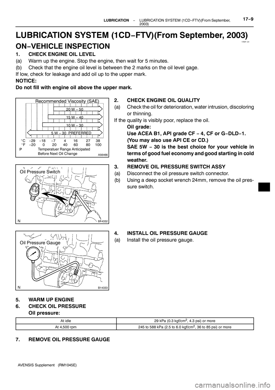
2. CHECK ENGINE OIL QUALITY
(a) Check the oil for deterioration, water intrusion, discoloring
or thinning.
If the quality is visibly poor, replace the oil.
Oil grade:
Use ACEA B1, API grade CF−4, CF or G−DLD−1.
(You may also use API CE or CD.)
SAE 5W−30 is the best choice for your vehicle in
terms of good fuel economy and good starting in cold
weather.
3. REMOVE OIL PRESSURE SWITCH ASSY
(a) Disconnect the oil pressure switch connector.
(b) Using a deep socket wrench 24mm, remove the oil pres-
sure switch.
4. INSTALL OIL PRESSURE GAUGE
(a) Install the oil pressure gauge.
5. WARM UP ENGINE
6. CHECK OIL PRESSURE
Oil pressure:
At idle29 kPa (0.3 kgf/cm2, 4.3 psi) or more
At 4,500 rpm245 to 588 kPa (2.5 to 6.0 kgf/cm2, 36 to 85 psi) or more
7. REMOVE OIL PRESSURE GAUGE
Page 4766 of 5135

I35328
(1)(2)
(3)
(4)
−
HEATER & AIR CONDITIONER W/PULLEY COMPRESSOR ASSY (2AZ −FSE)
55 −5
AVENSIS Supplement (RM1045E)
9. INSPECT COMPRESSOR OIL
(a) When replacing the w/pulley compressor assy with a new one, after gradually removing the refrigerant
gas from the service valve, drain the following amount of oil from the new w/pulley compressor assy
before installation.
Standard:
(Oil capacity inside new w/pulley compressor assy: 90 + 15 cc (3.0 + 0.5 fl. oz.) ) − (Remaining
oil amount in the removed w/pulley compressor assy) = (Oil amount to be removed when replac-
ing)
NOTICE:
S When checking the compressor oil level, observe the precautions on the cooler removal/instal-
lation.
S Since compressor oil remains in the pipes of the vehicle, if a new w/pulley compressor assy
is installed without removing some oil inside, the oil amount becomes excessive, preventing
heat exchange in the refrigerant cycle and causing refrigerant failure.
S If the remaining oil in the removed w/pulley compressor assy is too small in volume, check for
oil leakage.
S Be sure to use ND −OIL 8 for compressor oil.
10. INSTALL W/PULLEY COMPRESSOR ASSY
(a) Install the w/pulley compressor assy with the 4 bolts.
Torque: 29 N �m (300 kgf �cm, 2 1 ft �lbf)
NOTICE:
Tighten the bolts in the order shown in the illustration to
install the w/pulley compressor assy.
(b) Connect the connector.
11 . INSTALL FAN AND GENERATOR V BELT (See page 14− 5)
SST 09249 −63010
12. INSTALL COOLER REFRIGERANT DISCHARGE
HOSE NO. 1
(a) Remove the attached vinyl tape from the hose.
(b) Sufficiently apply compressor oil to a new O −ring and the
fitting surface of the w/pulley compressor assy.
Compressor oil: ND −OIL 8 or equivalent
(c) Install the O −ring on the cooler refrigerant discharge hose
No.1.
Page 5053 of 5135
A93668
A64026
B06777
A76720
A76721
14–34– ENGINE MECHANICALCYLINDER HEAD GASKET (1ZZ–FE/3ZZ–FE)(From
February, 2004)
AVENSIS REPAIR MANUAL SUPPLEMENT
(RM1098E)
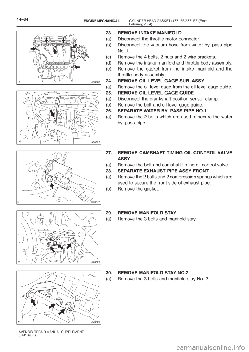
23. REMOVE INTAKE MANIFOLD
(a) Disconnect the throttle motor connector.
(b) Disconnect the vacuum hose from water by–pass pipe
No. 1.
(c) Remove the 4 bolts, 2 nuts and 2 wire brackets.
(d) Remove the intake manifold and throttle body assembly.
(e) Remove the gasket from the intake manifold and the
throttle body assembly.
24. REMOVE OIL LEVEL GAGE SUB–ASSY
(a) Remove the oil level gage from the oil level gage guide.
25. REMOVE OIL LEVEL GAGE GUIDE
(a) Disconnect the crankshaft position sensor clamp.
(b) Remove the bolt and oil level gage guide.
26. SEPARATE WATER BY–PASS PIPE NO.1
(a) Remove the 2 bolts which are used to secure the water
by–pass pipe.
27. REMOVE CAMSHAFT TIMING OIL CONTROL VALVE
ASSY
(a) Remove the bolt and camshaft timing oil control valve.
28. SEPARATE EXHAUST PIPE ASSY FRONT
(a) Remove the 2 bolts and 2 compression springs which are
used to secure the front side of exhaust pipe.
(b) Remove the gasket.
29. REMOVE MANIFOLD STAY
(a) Remove the 3 bolts and manifold stay.
30. REMOVE MANIFOLD STAY NO.2
(a) Remove the 3 bolts and manifold stay No. 2.
Page 5064 of 5135
B06777
A64026
A93668
A64023
A76713
– ENGINE MECHANICALCYLINDER HEAD GASKET (1ZZ–FE/3ZZ–FE)(From
February, 2004)14–45
AVENSIS REPAIR MANUAL SUPPLEMENT
(RM1098E)
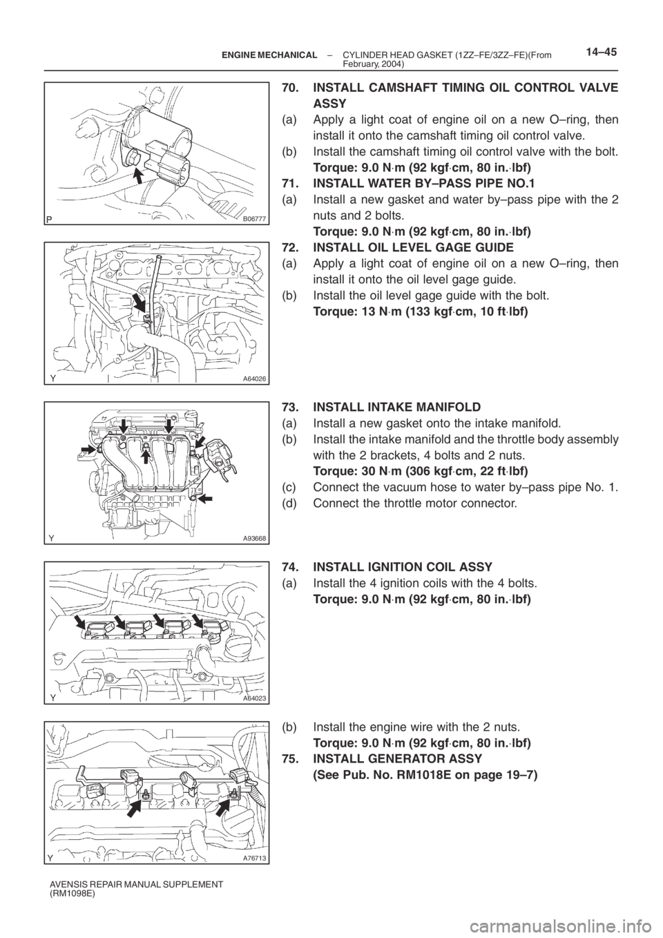
70. INSTALL CAMSHAFT TIMING OIL CONTROL VALVE
ASSY
(a) Apply a light coat of engine oil on a new O–ring, then
install it onto the camshaft timing oil control valve.
(b) Install the camshaft timing oil control valve with the bolt.
Torque: 9.0 N⋅m (92 kgf⋅cm, 80 in.⋅lbf)
71. INSTALL WATER BY–PASS PIPE NO.1
(a) Install a new gasket and water by–pass pipe with the 2
nuts and 2 bolts.
Torque: 9.0 N⋅m (92 kgf⋅cm, 80 in.⋅lbf)
72. INSTALL OIL LEVEL GAGE GUIDE
(a) Apply a light coat of engine oil on a new O–ring, then
install it onto the oil level gage guide.
(b) Install the oil level gage guide with the bolt.
Torque: 13 N⋅m (133 kgf⋅cm, 10 ft⋅lbf)
73. INSTALL INTAKE MANIFOLD
(a) Install a new gasket onto the intake manifold.
(b) Install the intake manifold and the throttle body assembly
with the 2 brackets, 4 bolts and 2 nuts.
Torque: 30 N⋅m (306 kgf⋅cm, 22 ft⋅lbf)
(c) Connect the vacuum hose to water by–pass pipe No. 1.
(d) Connect the throttle motor connector.
74. INSTALL IGNITION COIL ASSY
(a) Install the 4 ignition coils with the 4 bolts.
Torque: 9.0 N⋅m (92 kgf⋅cm, 80 in.⋅lbf)
(b) Install the engine wire with the 2 nuts.
Torque: 9.0 N⋅m (92 kgf⋅cm, 80 in.⋅lbf)
75. INSTALL GENERATOR ASSY
(See Pub. No. RM1018E on page 19–7)
Page 5073 of 5135
A64023
A93668
A64026
A96570
14–16– ENGINE MECHANICALPARTIAL ENGINE ASSY (1ZZ–FE/3ZZ–FE)(From
February, 2004)
AVENSIS REPAIR MANUAL SUPPLEMENT
(RM1098E)
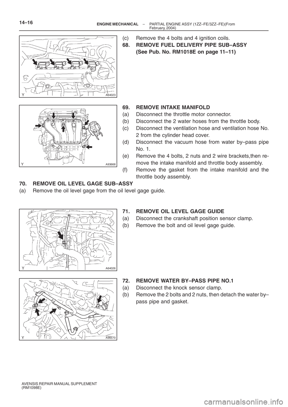
(c) Remove the 4 bolts and 4 ignition coils.
68. REMOVE FUEL DELIVERY PIPE SUB–ASSY
(See Pub. No. RM1018E on page 11–11)
69. REMOVE INTAKE MANIFOLD
(a) Disconnect the throttle motor connector.
(b) Disconnect the 2 water hoses from the throttle body.
(c) Disconnect the ventilation hose and ventilation hose No.
2 from the cylinder head cover.
(d) Disconnect the vacuum hose from water by–pass pipe
No. 1.
(e) Remove the 4 bolts, 2 nuts and 2 wire brackets,then re-
move the intake manifold and throttle body assembly.
(f) Remove the gasket from the intake manifold and the
throttle body assembly.
70. REMOVE OIL LEVEL GAGE SUB–ASSY
(a) Remove the oil level gage from the oil level gage guide.
71. REMOVE OIL LEVEL GAGE GUIDE
(a) Disconnect the crankshaft position sensor clamp.
(b) Remove the bolt and oil level gage guide.
72. REMOVE WATER BY–PASS PIPE NO.1
(a) Disconnect the knock sensor clamp.
(b) Remove the 2 bolts and 2 nuts, then detach the water by–
pass pipe and gasket.
Page 5079 of 5135
A96570
A64026
A93668
A64023
A76713
14–22– ENGINE MECHANICALPARTIAL ENGINE ASSY (1ZZ–FE/3ZZ–FE)(From
February, 2004)
AVENSIS REPAIR MANUAL SUPPLEMENT
(RM1098E)
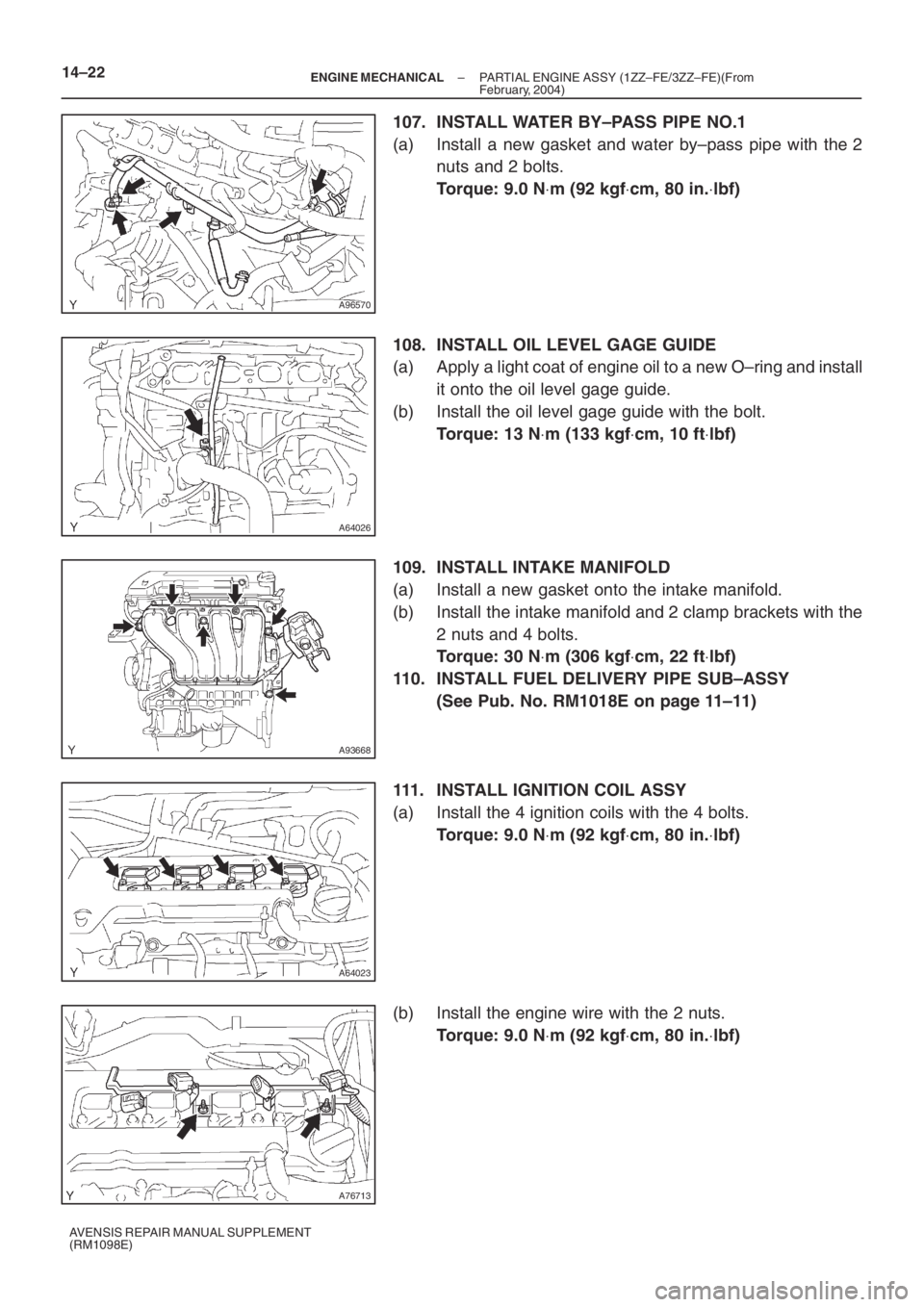
107. INSTALL WATER BY–PASS PIPE NO.1
(a) Install a new gasket and water by–pass pipe with the 2
nuts and 2 bolts.
Torque: 9.0 N⋅m (92 kgf⋅cm, 80 in.⋅lbf)
108. INSTALL OIL LEVEL GAGE GUIDE
(a) Apply a light coat of engine oil to a new O–ring and install
it onto the oil level gage guide.
(b) Install the oil level gage guide with the bolt.
Torque: 13 N⋅m (133 kgf⋅cm, 10 ft⋅lbf)
109. INSTALL INTAKE MANIFOLD
(a) Install a new gasket onto the intake manifold.
(b) Install the intake manifold and 2 clamp brackets with the
2 nuts and 4 bolts.
Torque: 30 N⋅m (306 kgf⋅cm, 22 ft⋅lbf)
110. INSTALL FUEL DELIVERY PIPE SUB–ASSY
(See Pub. No. RM1018E on page 11–11)
111. INSTALL IGNITION COIL ASSY
(a) Install the 4 ignition coils with the 4 bolts.
Torque: 9.0 N⋅m (92 kgf⋅cm, 80 in.⋅lbf)
(b) Install the engine wire with the 2 nuts.
Torque: 9.0 N⋅m (92 kgf⋅cm, 80 in.⋅lbf)