Page 2610 of 5135
F42292
F42290
To
Master
Cylinder
FrontTo Master
Cylinder
Rear
To Rear
Wheel RH
To Front Wheel LHTo Front Wheel RH
To Rear
Wheel LH
AA
A
A
BB
32±58
±
BRAKE BRAKE ACTUATOR ASSY (W/ VSC)
AVENSIS REPAIR MANUAL (RM1018E)
5. REMOVE BRAKE ACTUATOR ASSY
(a) Remove the 3 bolts and brake actuator from the brake acutuator bracket.
6. REMOVE OIL PRESSURE SENSOR
7. REMOVE SKID CONTROL ECU
(a) Disconnect the connector from the skid control ECU.
(b) Using a torx driver (T20), remove the 6 screws and the skid control EC\
U from the brake actuator.
8. INSTALL SKID CONTROL ECU
(a) Install the skid control ECU and 6 screws with a torx driver (T20).
(b) Connect the connector to the skid control ECU.
9. INSTALL OIL PRESSURE SENSOR
10. INSTALL BRAKE ACTUATOR ASSY
(a) Install the brake actuator with 3 the bolts to the brake actuator bracke\
t. Torque: 4.7 N �m (48 kgf �cm, 42 in. �lbf)
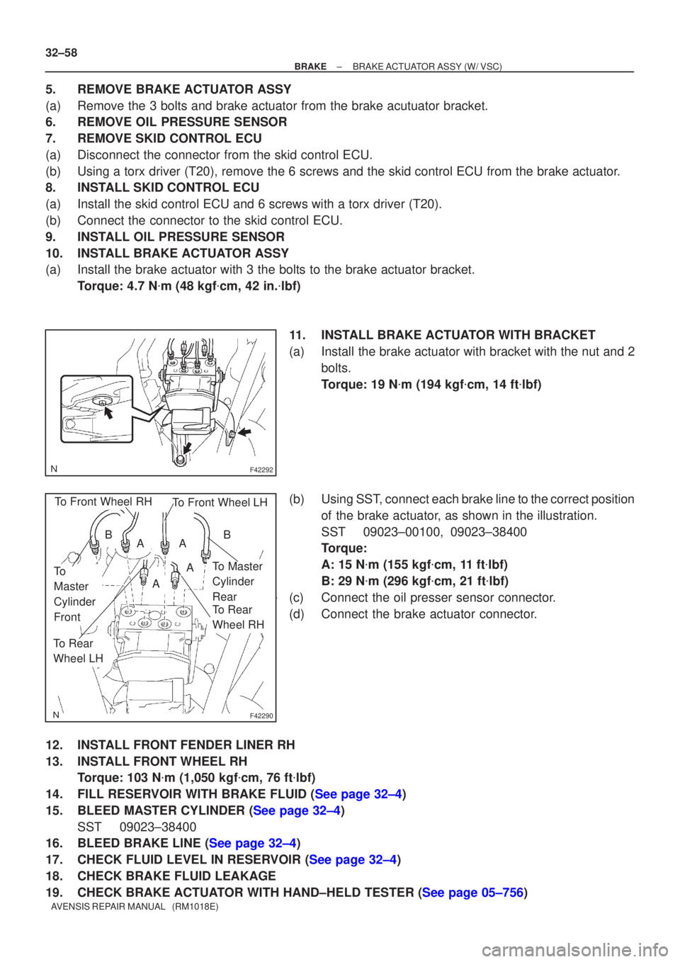
11. INSTALL BRAKE ACTUATOR WITH BRACKET
(a) Install the brake actuator with bracket with the nut and 2 bolts.
Torque: 19 N �m (194 kgf �cm, 14 ft �lbf)
(b) Using SST, connect each brake line to the correct position of the brake actuator, as shown in the illustration.
SST 09023±00100, 09023±38400
Torque:
A: 15 N �m (155 kgf �cm, 11 ft �lbf)
B: 29 N �m (296 kgf �cm, 21 ft �lbf)
(c) Connect the oil presser sensor connector.
(d) Connect the brake actuator connector.
12. INSTALL FRONT FENDER LINER RH
13. INSTALL FRONT WHEEL RH Torque: 103 N �m (1,050 kgf �cm, 76 ft �lbf)
14.FILL RESERVOIR WITH BRAKE FLUID (See page 32±4)
15.BLEED MASTER CYLINDER (See page 32±4) SST 09023±38400
16.BLEED BRAKE LINE (See page 32±4)
17.CHECK FLUID LEVEL IN RESERVOIR (See page 32±4)
18. CHECK BRAKE FLUID LEAKAGE
19.CHECK BRAKE ACTUATOR WITH HAND±HELD TESTER (See page 05±756)
Page 2626 of 5135
F45419
Cylinder Slide Pin
Lithium soap base glycol grease
F45421
Union Bolt
±
BRAKE FRONT BRAKE
32±45
AVENSIS REPAIR MANUAL (RM1018E)
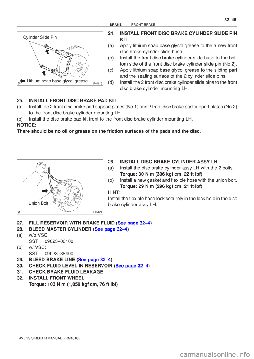
24. INSTALL FRONT DISC BRAKE CYLINDER SLIDE PIN
KIT
(a) Apply lithium soap base glycol grease to the a new front
disc brake cylinder slide bush.
(b) Install the front disc brake cylinder slide bush to the bot- tom side of the front disc brake cylinder slide pin (No.2).
(c) Apply lithium soap base glycol grease to the sliding part
and the sealing surface of the 2 cylinder slide pins.
(d) Install the 2 front disc brake cylinder slide pins to the front disc brake cylinder mounting LH.
25. INSTALL FRONT DISC BRAKE PAD KIT
(a) Install the 2 front disc brake pad support plates (No.1) and 2 front disc bra\
ke pad support plates (No.2) to the front disc brake cylinder mounting LH.
(b) Install the disc brake pad kit front to the front disc brake cylinder mo\
unting LH.
NOTICE:
There should be no oil or grease on the friction surfaces of the pads an\
d the disc.
26. INSTALL DISC BRAKE CYLINDER ASSY LH
(a) Install the disc brake cylinder assy LH with the 2 bolts.Torque: 30 N �m (306 kgf �cm, 22 ft �lbf)
(b) Install a new gasket and flexible hose with the union bolt.
Torque: 29 N �m (296 kgf �cm, 21 ft �lbf)
HINT:
Install the flexible hose lock securely in the lock hole in the disc
brake cylinder assy LH.
27.FILL RESERVOIR WITH BRAKE FLUID (See page 32±4)
28.BLEED MASTER CYLINDER (See page 32±4)
(a) w/o VSC: SST 09023±00100
(b) w/ VSC: SST 09023±38400
29.BLEED BRAKE LINE (See page 32±4)
30.CHECK FLUID LEVEL IN RESERVOIR (See page 32±4)
31. CHECK BRAKE FLUID LEAKAGE
32. INSTALL FRONT WHEEL
Torque: 103 N �m (1,050 kgf �cm, 76 ft �lbf)
Page 2649 of 5135
400D7±02
D25120
OK if hot
Add if hot 40±2
± AUTOMATIC TRANSMISSION / TRANSAUTOMATIC TRANSAXLE FLUID (ATM)
AVENSIS REPAIR MANUAL (RM1018E)
AUTOMATIC TRANSAXLE FLUID (ATM)
ON±VEHICLE INSPECTION
1. CHECK THE FLUID LEVEL
HINT:
Drive the vehicle so that the engine and transaxle are at the nor-
mal operating temperature.
Fluid temperature: 70 ± 80 �C (158 ± 176 �F)
(a) Park the vehicle on a level surface and set the parking
brake.
(b) With the engine idling and the brake pedal depressed,
shift the shift lever into all position from P to L position and
return to P position.
(c) Pull out the dipstick and wipe it clean.
(d) Push it back fully into the pipe.
(e) Pull it out and check that the fluid level is in the HOT posi-
tion.
If there are leaks, it is necessary to repair or replace O±rings,
FIPGs, oil seals, plugs or other parts.
Page 2694 of 5135
D30342
D30343
D30346
D30344
40±26
±
AUTOMATIC TRANSMISSION / TRANS AUTOMATIC TRANSAXLE ASSY (U241E)
AVENSIS REPAIR MANUAL (RM1018E)
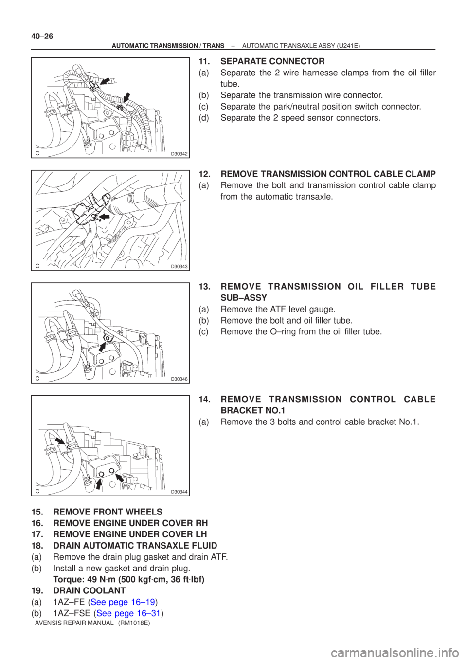
11. SEPARATE CONNECTOR
(a) Separate the 2 wire harnesse clamps from the oil filler tube.
(b) Separate the transmission wire connector.
(c) Separate the park/neutral position switch connector.
(d) Separate the 2 speed sensor connectors.
12. REMOVE TRANSMISSION CONTROL CABLE CLAMP
(a) Remove the bolt and transmission control cable clamp from the automatic transaxle.
13. REMOVE TRANSMISSION OIL FILLER TUBE SUB±ASSY
(a) Remove the ATF level gauge.
(b) Remove the bolt and oil filler tube.
(c) Remove the O±ring from the oil filler tube.
14. REMOVE TRANSMISSION CONTROL CABLE BRACKET NO.1
(a) Remove the 3 bolts and control cable bracket No.1.
15. REMOVE FRONT WHEELS
16. REMOVE ENGINE UNDER COVER RH
17. REMOVE ENGINE UNDER COVER LH
18. DRAIN AUTOMATIC TRANSAXLE FLUID
(a) Remove the drain plug gasket and drain ATF.
(b) Install a new gasket and drain plug. Torque: 49 N �m (500 kgf �cm, 36 ft �lbf)
19. DRAIN COOLANT
(a)1AZ±FE (See pege 16±19)
(b)1AZ±FSE (See pege 16±31)
Page 2702 of 5135
D30345
D30344
B
AA
D30346
D30343
40±34
± AUTOMATIC TRANSMISSION / TRANSAUTOMATIC TRANSAXLE ASSY (U241E)
AVENSIS REPAIR MANUAL (RM1018E)
Torque: 103 N�m (1,050 kgf�cm, 76 ft�lbf)
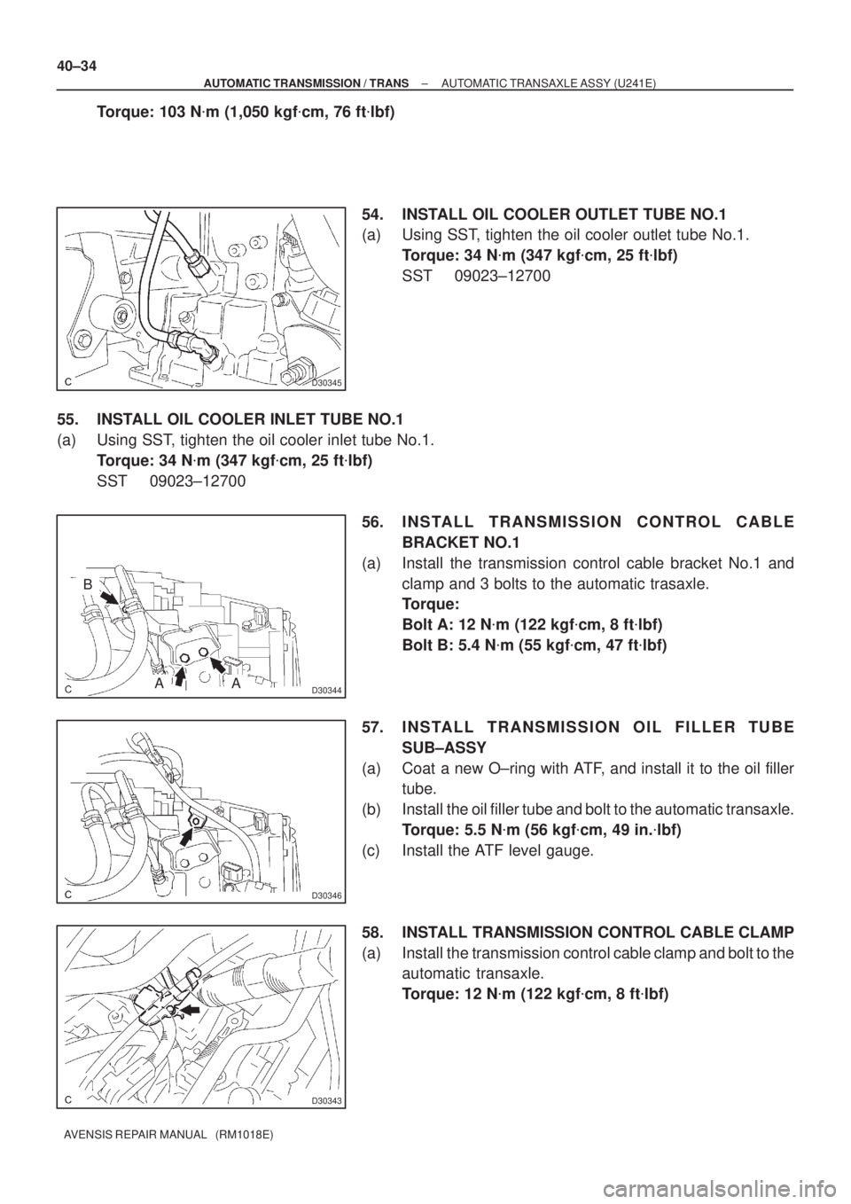
54. INSTALL OIL COOLER OUTLET TUBE NO.1
(a) Using SST, tighten the oil cooler outlet tube No.1.
Torque: 34 N�m (347 kgf�cm, 25 ft�lbf)
SST 09023±12700
55. INSTALL OIL COOLER INLET TUBE NO.1
(a) Using SST, tighten the oil cooler inlet tube No.1.
Torque: 34 N�m (347 kgf�cm, 25 ft�lbf)
SST 09023±12700
56. INSTALL TRANSMISSION CONTROL CABLE
BRACKET NO.1
(a) Install the transmission control cable bracket No.1 and
clamp and 3 bolts to the automatic trasaxle.
Torque:
Bolt A: 12 N�m (122 kgf�cm, 8 ft�lbf)
Bolt B: 5.4 N�m (55 kgf�cm, 47 ft�lbf)
57. INSTALL TRANSMISSION OIL FILLER TUBE
SUB±ASSY
(a) Coat a new O±ring with ATF, and install it to the oil filler
tube.
(b) Install the oil filler tube and bolt to the automatic transaxle.
Torque: 5.5 N�m (56 kgf�cm, 49 in.�lbf)
(c) Install the ATF level gauge.
58. INSTALL TRANSMISSION CONTROL CABLE CLAMP
(a) Install the transmission control cable clamp and bolt to the
automatic transaxle.
Torque: 12 N�m (122 kgf�cm, 8 ft�lbf)
Page 2705 of 5135
40120±01
D30355
: Specified torqueBattery
13 (132, 10)
Automatic
Transaxle Assy
ATF Level Gauge
9.8 (100, 87 in.�lbf)
Transmission
Oil Filler Tube
Sub±assy
37 (377, 27)5.5 (56, 49 in.�lbf)
Starter Assy
12 (122, 9)
Clip
Transmission Control
Cable Assy
12 (122, 8)
7.0 (71, 62 in.�lbf)
Hood Sub±assyEngine Room Cover Side
Radiator Suppot
OpeningCover
Air Cleaner Assy
5.0 (50, 44 in.�lbf)
5.0 (51, 44 in.�lbf)
12 (122, 8)
8.4 (86, 74 in.�lbf)
�Non±reusable Part�O±ring
Transmission Control
Cable Clamp
Transmission Control
Cable Bracket No.1
5.4 (55, 47 in.�lbf)
Oil Cooler Inlet Tube No.1
34 (347, 25)
Oil Cooler
Outlet Tube No.1
Engine Cover
Sub±assy No.1
1AZ±FSE
N�m (kgf�cm, ft�lbf)
Battery Carrier
13 (132, 100)
13 (132, 100)
Clamp
± AUTOMATIC TRANSMISSION / TRANSAUTOMATIC TRANSAXLE ASSY (U241E)
40±23
AVENSIS REPAIR MANUAL (RM1018E)
AUTOMATIC TRANSAXLE ASSY (U241E)
COMPONENTS
Page 2708 of 5135
C91880
C80991
C91884
40±12
±
AUTOMATIC TRANSMISSION / TRANS AUTOMATIC TRANSAXLE ASSY (U341E)
AVENSIS REPAIR MANUAL (RM1018E)
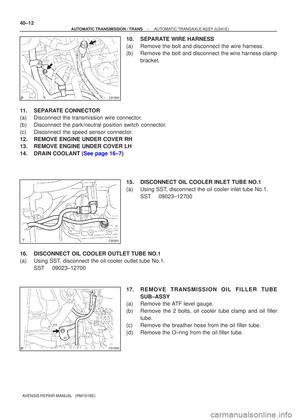
10. SEPARATE WIRE HARNESS
(a) Remove the bolt and disconnect the wire harness.
(b) Remove the bolt and disconnect the wire harness clamp bracket.
11. SEPARATE CONNECTOR
(a) Disconnect the transmission wire connector.
(b) Disconnect the park/neutral position switch connector.
(c) Disconnect the speed sensor connector.
12. REMOVE ENGINE UNDER COVER RH
13. REMOVE ENGINE UNDER COVER LH
14.DRAIN COOLANT (See page 16±7) 15. DISCONNECT OIL COOLER INLET TUBE NO.1
(a) Using SST, disconnect the oil cooler inlet tube No.1.SST 09023±12700
16. DISCONNECT OIL COOLER OUTLET TUBE NO.1
(a) Using SST, disconnect the oil cooler outlet tube No.1. SST 09023±12700
17. REMOVE TRANSMISSION OIL FILLER TUBESUB±ASSY
(a) Remove the ATF level gauge.
(b) Remove the 2 bolts, oil cooler tube clamp and oil filler
tube.
(c) Remove the breather hose from the oil filler tube.
(d) Remove the O±ring from the oil filler tube.
Page 2716 of 5135
C94723
C91882
������C87398
A
B
C80991
40±20
± AUTOMATIC TRANSMISSION / TRANSAUTOMATIC TRANSAXLE ASSY (U341E)
AVENSIS REPAIR MANUAL (RM1018E)
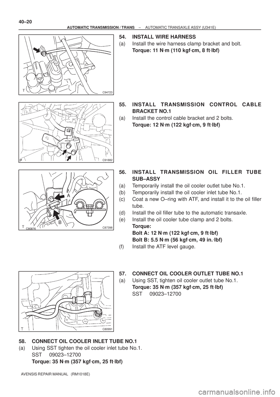
54. INSTALL WIRE HARNESS
(a) Install the wire harness clamp bracket and bolt.
Torque: 11 N�m (110 kgf�cm, 8 ft�lbf)
55. INSTALL TRANSMISSION CONTROL CABLE
BRACKET NO.1
(a) Install the control cable bracket and 2 bolts.
Torque: 12 N�m (122 kgf�cm, 9 ft�lbf)
56. INSTALL TRANSMISSION OIL FILLER TUBE
SUB±ASSY
(a) Temporarily install the oil cooler outlet tube No.1.
(b) Temporarily install the oil cooler inlet tube No.1.
(c) Coat a new O±ring with ATF, and install it to the oil filler
tube.
(d) Install the oil filler tube to the automatic transaxle.
(e) Install the oil cooler tube clamp and 2 bolts.
Torque:
Bolt A: 12 N�m (122 kgf�cm, 9 ft�lbf)
Bolt B: 5.5 N�m (56 kgf�cm, 49 in.�lbf)
(f) Install the ATF level gauge.
57. CONNECT OIL COOLER OUTLET TUBE NO.1
(a) Using SST, tighten oil cooler outlet tube No.1.
Torque: 35 N�m (357 kgf�cm, 25 ft�lbf)
SST 09023±12700
58. CONNECT OIL COOLER INLET TUBE NO.1
(a) Using SST tighten the oil cooler inlet tube No.1.
SST 09023±12700
Torque: 35 N�m (357 kgf�cm, 25 ft�lbf)