Page 2159 of 5135
A77328
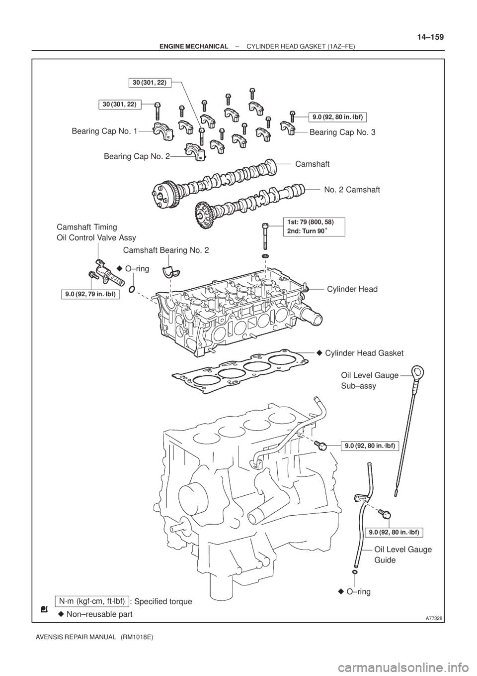
N´m (kgf´cm, ft´lbf)
: Specified torque
� Non±reusable part
30 (301, 22)
� O±ring
Bearing Cap No. 1
Bearing Cap No. 2
9.0 (92, 80 in.�lbf)
Bearing Cap No. 3
Camshaft
No. 2 Camshaft
Camshaft Bearing No. 2
Camshaft Timing
Oil Control Valve Assy
Cylinder Head
� Cylinder Head Gasket
9.0 (92, 80 in.�lbf)
Oil Level Gauge
Sub±assy
9.0 (92, 80 in.�lbf)
� O±ring
Oil Level Gauge
Guide
1st: 79 (800, 58)
2nd: Turn 90�
30 (301, 22)
9.0 (92, 79 in.�lbf)
± ENGINE MECHANICALCYLINDER HEAD GASKET (1AZ±FE)
14±159
AVENSIS REPAIR MANUAL (RM1018E)
Page 2207 of 5135

14±211
AVENSIS REPAIR MANUAL (RM1018E)
80.REMOVE INTAKE AIR CONTROL VALVE ASSY
(a)Remove the intake air control valve and a g")
A32676
A77350
A52497
±
ENGINE MECHANICAL PARTIAL ENGINE ASSY(1AZ±FSE)
14±211
AVENSIS REPAIR MANUAL (RM1018E)
80.REMOVE INTAKE AIR CONTROL VALVE ASSY
(a)Remove the intake air control valve and a gasket.
81.REMOVE SURGE TANK STAY NO.1
(a)Remove the 3 bolts and the surge tank stay.
82.REMOVE INTAKE MANIFOLD INSULATOR NO.2
83.REMOVE NOZZLE HOLDER CLAMP
84.REMOVE FUEL DELIVERY PIPE SUB±ASSY (See page 11±42)
85.REMOVE FUEL INJECTOR ASSY (See page 11±42)
86. REMOVE V±RIBBED BELT TENSIONER ASSY
(a) Remove the bolt and nut, and then detach the V±ribbedbelt tensioner.
87. REMOVE IGNITION COIL ASSY
(a) Remove the 4 bolts and the ignition coils.
88. REMOVE EXHAUST MANIFOLD HEAT INSULATOR NO.1
(a) Remove the 3 bolts and the exhaust manifold heat insulator. 89. REMOVE EXHAUST MANIFOLD CONVERTERSUB±ASSY
(a) Remove the 2 bolts and 2 nuts, then detach the No. 1 and No. 2 exhaust manifold stay.
(b) Remove the 5 nuts, the exhaust manifold converter and gasket.
90. REMOVE OIL LEVEL GAGE SUB±ASSY
91. REMOVE OIL LEVEL GAGE GUIDE
92. REMOVE WATER INLET
(a) Remove the 2 nuts and the water inlet.
93. REMOVE THERMOSTAT
Page 2208 of 5135

AVENSIS REPAIR MANUAL (RM1018E)
94.REMOVE WATER BY±PASS PIPE NO.1
(a)Remove the 2 bolts and 2 nuts.
(b)Remove t")
A78645
Oil Pressure Switch
14±212
±
ENGINE MECHANICAL PARTIAL ENGINE ASSY(1AZ±FSE)
AVENSIS REPAIR MANUAL (RM1018E)
94.REMOVE WATER BY±PASS PIPE NO.1
(a)Remove the 2 bolts and 2 nuts.
(b)Remove the water by±pass pipe No. 1 and a gasket.
95.REMOVE KNOCK SENSOR
(a)Remove the nut and the knock sensor. 96.REMOVE ENGINE OIL PRESSURE SWITCH ASSY
(a)Using SST, remove the engine oil pressure switch.SST09268±46021
97.REMOVE E.F.I. ENGINE COOLANT TEMPERATURE SENSOR
(a)Using a SST, remove the coolant temperature sensor SST09817±33190
98.REPLACE PARTIAL ENGINE ASSY
99.INSTALL E.F.I. ENGINE COOLANT TEMPERATURE SENSOR
(a)Install a new gasket to the engine coolant temperature sensor.
(b)Using SST, install the engine coolant temperature sensor. SST09817±33190
Torque: 20 N �m (208 kgf �cm,15 ft �lbf)
100.INSTALL ENGINE OIL PRESSURE SWITCH ASSY
(a)Clean the threads of the oil pressure switch, apply adhesive there.
Adhesive: Part No. 08833 ± 00080 THREE BOND 1344 or equivalent.
(b)Install the oil pressure switch. Torque: 15 N �m (153 kgf �cm,11 ft �lbf)
SST09268±46021
101.INSTALL KNOCK SENSOR Torque: 20 N �m (208 kgf �cm,15 ft �lbf)
102.INSTALL WATER BY±PASS PIPE NO.1
(a)Install the water by±pass pipe No. 1 and a new gasket.
(b)Install the 2 bolts and 2 nuts. Torque: 9.0 N �m (92 kgf �cm,80 in. �lbf)
103.INSTALL THERMOSTAT (See page 16±35)
104. INSTALL WATER INLET Torque: 9.0 N �m (92 kgf �cm, 80 in. �lbf)
105. INSTALL OIL LEVEL GAGE GUIDE
(a) Apply a light coat of engine oil to the O±ring, install it to the oil\
level gauge guide.
(b) Install the oil level gauge and guide with the bolt. Torque: 9.0 N �m (92 kgf �cm, 80 in. �lbf)
Page 2224 of 5135
A77499
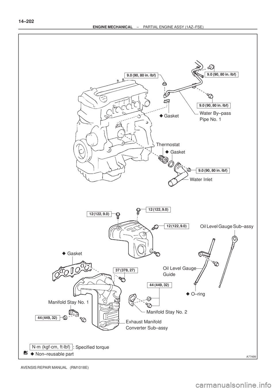
N´m (kgf´cm, ft´lbf)
: Specified torque
� Non±reusable part� GasketWater By±pass
Pipe No. 1 � Gasket
Thermostat
9.0 (90, 80 in.�lbf)
Water Inlet
37 (378, 27)Oil Level Gauge
Guide
� O±ring
Manifold Stay No. 2
Exhaust Manifold
Converter Sub±assy Manifold Stay No. 1
9.0 (90, 80 in.�lbf)
9.0 (90, 80 in.�lbf)
� Gasket
9.0 (90, 80 in.�lbf)
12 (122, 9.0)12 (122, 9.0)
12 (122, 9.0)
44 (449, 32)
44 (449, 32)
Oil Level Gauge Sub±assy
14±202
± ENGINE MECHANICALPARTIAL ENGINE ASSY (1AZ±FSE)
AVENSIS REPAIR MANUAL (RM1018E)
Page 2241 of 5135
A79424
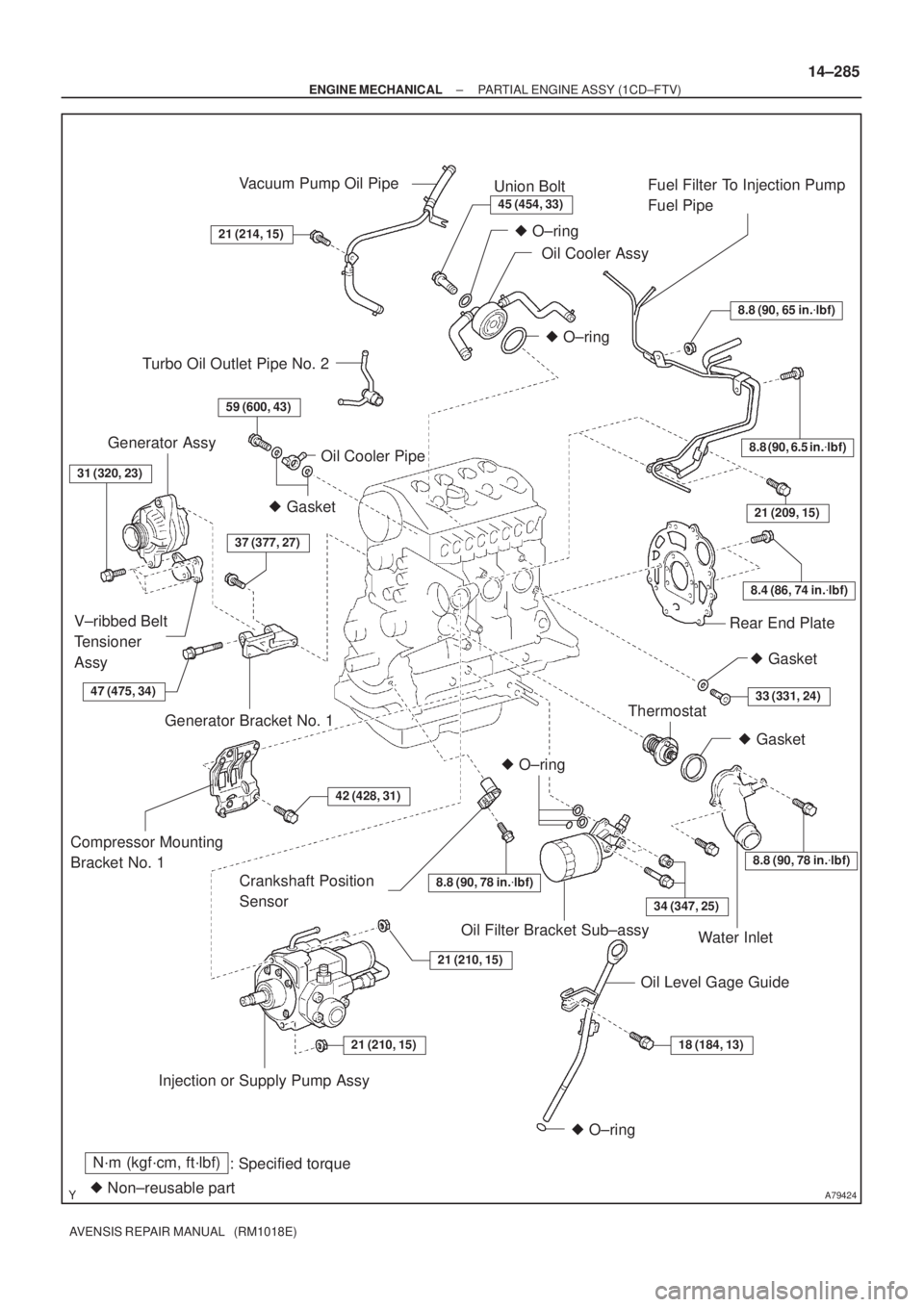
N´m (kgf´cm, ft´lbf)
: Specified torque
� Non±reusable part
8.8 (90, 65 in.�lbf)
8.8 (90, 6.5 in.�lbf)
8.4 (86, 74 in.�lbf)
21 (209, 15)
8.8 (90, 78 in.�lbf)
34 (347, 25)
18 (184, 13)21 (210, 15)
21 (210, 15)
42 (428, 31)
37 (377, 27)
59 (600, 43)
21 (214, 15)
45 (454, 33)
� O±ring
� O±ring
� Gasket
� O±ring
� O±ring
Vacuum Pump Oil Pipe
Union Bolt
Oil Cooler AssyFuel Filter To Injection Pump
Fuel Pipe
Rear End Plate
Crankshaft Position
Sensor
Thermostat
Water Inlet
Oil Level Gage Guide Oil Filter Bracket Sub±assy
Injection or Supply Pump Assy Compressor Mounting
Bracket No. 1Generator Bracket No. 1 V±ribbed Belt
Tensioner
AssyGenerator Assy
Oil Cooler Pipe
� Gasket
Turbo Oil Outlet Pipe No. 2
31 (320, 23)
� Gasket
33 (331, 24)
8.8 (90, 78 in.�lbf)
47 (475, 34)
± ENGINE MECHANICALPARTIAL ENGINE ASSY (1CD±FTV)
14±285
AVENSIS REPAIR MANUAL (RM1018E)
Page 2272 of 5135
A77328
N´m (kgf´cm, ft´lbf)
: Specified torque
� Non±reusable part
30 (301, 22)
� O±ring
Bearing Cap No. 1
Bearing Cap No. 2
9.0 (92, 80 in.�lbf)
Bearing Cap No. 3
Camshaft
No. 2 Camshaft
Camshaft Bearing No. 2
Camshaft Timing
Oil Control Valve Assy
Cylinder Head
� Cylinder Head Gasket
9.0 (92, 80 in.�lbf)
Oil Level Gauge
Sub±assy
9.0 (92, 80 in.�lbf)
� O±ring
Oil Level Gauge
Guide
1st: 79 (800, 58)
2nd: Turn 90�
30 (301, 22)
9.0 (92, 79 in.�lbf)
± ENGINE MECHANICALCYLINDER HEAD GASKET (1AZ±FSE)
14±253
AVENSIS REPAIR MANUAL (RM1018E)
Page 2304 of 5135

14±321
AVENSIS REPAIR MANUAL (RM1018E)
40. SET NO. 1 CYLINDER TO TDC/COMPRESSION
(a) Using t")
90�
A09683
TDC Mark
Dot Mark
A09624
A09625
A09626
Alignment Mark
± ENGINE MECHANICALCAMSHAFT (1CD±FTV)
14±321
AVENSIS REPAIR MANUAL (RM1018E)
40. SET NO. 1 CYLINDER TO TDC/COMPRESSION
(a) Using the crankshaft pulley bolt, turn the crankshaft to set
the dot mark of the crankshaft timing pulley at the position
of 90� BTDC.
NOTICE:
If the timing belt is disengaged, having the crankshaft tim-
ing pulley at wrong angle can cause the piston head and
valve head to come into contact with each other.
41. INSTALL CAMSHAFT
NOTICE:
Since the thrust clearance of the camshaft is small, the
camshaft must be kept level while it is being installed. If the
camshaft is not kept level, damage to the cylinder head or
the camshaft may result. To avoid this, the following proce-
dures should be carried out.
(a) Place the camshaft carrier on the cylinder head.
(b) Install the camshaft sub±assy No. 1.
(c) Apply engine oil to the cam and gear of the camshaft, and
the journal of the camshaft carrier.
(d) Place the intake camshaft on the camshaft carrier as
shown in the illustration so that the No. 3 and No. 4 of cyl-
inder cam lobes face downward.
42. INSTALL NO.2 CAMSHAFT
(a) Install the camshaft sub±assy No. 2.
(b) Apply engine oil to the cam and gear of the camshaft, and
the journal of the camshaft carrier.
(c) Engage the exhaust camshaft gear and the intake cam-
shaft gear by aligning the alignment marks on each gear.
(d) Roll down the exhaust camshaft onto the bearing journals
while engaging gears with each other.
Page 2330 of 5135

AVENSIS REPAIR MANUAL (RM1018E)
93.REMOVE INTAKE MANIFOLD INSULATOR NO.1
(a)Remove the 2 bolts and the intake manifold")
A79150
A61175
A09671
14±294
±
ENGINE MECHANICAL PARTIAL ENGINE ASSY(1CD±FTV)
AVENSIS REPAIR MANUAL (RM1018E)
93.REMOVE INTAKE MANIFOLD INSULATOR NO.1
(a)Remove the 2 bolts and the intake manifold insulator.
94.REMOVE COMMON RAIL ASSY (See page 11±78) 95.REMOVE POWER STEERING IDLE PULLEY
BRACKET
(a)Remove the 3 bolts and the idle pulley bracket.
96.REMOVE INTAKE MANIFOLD
(a)Remove the 2 bolts and the wiring harness clamp bracket.
(b)Remove the 8 bolts and 2 nuts, and then remove the in- take manifold and the gasket.
97.REMOVE INJECTION PUMP DRIVE PULLEY (See page 11±69) SST 09960±10010 (09962±01000, 09963±01000)
98. REMOVE TIMING BELT NO.3 COVER
(a) Remove the 2 bolts and 2 seal washers, and then remove the timing belt c\
over.
99.REMOVE OIL LEVEL GAGE GUIDE (See page 17±22)
100.REMOVE INJECTION OR SUPPLY PUMP ASSY (See page 11±69)
101. REMOVE COMPRESSOR MOUNTING BRACKET NO.1
(a) Remove the 4 bolts and the compressor mounting bracket.
102. REMOVE WATER INLET
(a) Remove the 2 bolts and the water inlet.
103. REMOVE THERMOSTAT
104. REMOVE OIL COOLER PIPE
(a) Remove the union bolt, the oil cooler pipe and the gasket.
105. REMOVE FUEL FILTER TO INJECTION PUMP FUEL PIPE
(a) Remove the 3 bolts and nut, and then detach the fuel pipe.