Page 403 of 4555
![NISSAN X-TRAIL 2005 Service Repair Manual SERVICE DATA AND SPECIFICATIONS (SDS)
CO-47
[YD22DDTi]
C
D
E
F
G
H
I
J
K
L
MA
CO
SERVICE DATA AND SPECIFICATIONS (SDS)PFP:00030
Standard and LimitEBS00CU0
CAPACITY
Unit: (lmp qt)
THERMOSTAT
RADIAT NISSAN X-TRAIL 2005 Service Repair Manual SERVICE DATA AND SPECIFICATIONS (SDS)
CO-47
[YD22DDTi]
C
D
E
F
G
H
I
J
K
L
MA
CO
SERVICE DATA AND SPECIFICATIONS (SDS)PFP:00030
Standard and LimitEBS00CU0
CAPACITY
Unit: (lmp qt)
THERMOSTAT
RADIAT](/manual-img/5/57403/w960_57403-402.png)
SERVICE DATA AND SPECIFICATIONS (SDS)
CO-47
[YD22DDTi]
C
D
E
F
G
H
I
J
K
L
MA
CO
SERVICE DATA AND SPECIFICATIONS (SDS)PFP:00030
Standard and LimitEBS00CU0
CAPACITY
Unit: (lmp qt)
THERMOSTAT
RADIATOR
Unit: kPa (bar, kg/cm2 , psi)
Tightening TorqueEBS00BKE
Unit: N·m (kg-m, ft-lb)
Unit: N·m (kg-m, in-lb)*
Engine coolant capacity (With reservoir tank at “MAX” level) Approx 9.5 (8-3/8)
Reservoir tank0.7 (5/8)
Valve opening temperature 80 - 84°C (176 - 183°F)
Full open lift amount More than 10 mm/ 95°C (0.39 in/203°F)
Valve closing temperature More than 77°C (171°F)
Cap relief pressureStandard 78 - 98 (0.78 - 0.98, 0.8 - 1.0, 11 - 14)
Limit 59 (0.59, 0.6, 9)
Leakage test pressure 157 (1.57, 1.6, 23)
Air relief plug7.4 (0.75, 65)*
Radiator mounting bracket
Cooling fan assembly
Cooling fan
Cooling fan motor (RH and LH)5.5 (0.56, 49)*
5.5 (0.56, 49)*
3.43 (0.35, 30)*
4.41 (0.45, 39)*
Water pump
Water pump pulley
Water inlet
Thermostat housing
Water inlet pipe
Heater return pipe26.5 (2.7, 20)
8.5 (0.86, 75)*
25 (2.6, 18)
25 (2.6, 18)
25 (2.6, 18)
25 (2.6, 18)
Page 2679 of 4555
![NISSAN X-TRAIL 2005 Service Repair Manual REMOVAL AND INSTALLATION
AT-415
[ALL]
D
E
F
G
H
I
J
K
L
MA
B
AT
21. Remove fluid cooler tube.
INSPECTION
Installation and inspection of torque converter
� After inserting a torque converter to a tra NISSAN X-TRAIL 2005 Service Repair Manual REMOVAL AND INSTALLATION
AT-415
[ALL]
D
E
F
G
H
I
J
K
L
MA
B
AT
21. Remove fluid cooler tube.
INSPECTION
Installation and inspection of torque converter
� After inserting a torque converter to a tra](/manual-img/5/57403/w960_57403-2678.png)
REMOVAL AND INSTALLATION
AT-415
[ALL]
D
E
F
G
H
I
J
K
L
MA
B
AT
21. Remove fluid cooler tube.
INSPECTION
Installation and inspection of torque converter
� After inserting a torque converter to a transaxle, be sure to
check distance “A” to ensure it is within the reference value limit.
InstallationECS004ND
Install the removed parts in the reverse order of the removal, while paying attention to the following work.
�When installing transaxle to the engine, attach the fixing bolts in
accordance with the following standard.
�Align the positions of tightening bolts for drive plate with those of
the torque converter, and temporarily tighten the bolts. Then,
tighten the bolts to the specified torque. Refer to AT- 4 1 6 , "
Com-
ponents" .
CAUTION:
�When turning crankshaft, turn it clockwise as viewed from
the front of the engine.
�When tightening the tightening bolts for the torque con-
verter after fixing the crankshaft pulley bolts, be sure to
confirm the tightening torque of the crankshaft pulley
mounting bolts.
� After converter is installed to drive plate, rotate crankshaft
several turns and check to be sure that transaxle rotates freely without binding.
�After completing installation, check for fluid leakage, fluid level, and the positions of A/T. Refer to AT- 1 6 ,
"Checking A/T Fluid" , AT- 4 0 9 , "CONTROL CABLE ADJUSTMENT" .
SCIA2596E
Distance “A”
QR20DE models: 19.0 mm (0.75 in) or more
QR25DE models: 14.0 mm (0.55 in) or more
SAT573D
Bolt No.Tightening torque
N·m (kg-m, ft-lb)Bolt length “ L ”
mm (in)
1
75 (7.7, 55)49 (1.93)
2 45 (1.77)
3
43 (4.4, 32)40 (1.57)
4 30 (1.18)
5
36 (3.7, 27)40 (1.57)
6 45 (1.97)
SCIA0795E
SCIA3138E
Page 3188 of 4555

ATC-10
PRECAUTIONS
Precautions for Servicing CompressorEJS000T5
�Plug all openings to prevent moisture and foreign matter from entering.
�When the compressor is removed, store it in the same position as it is when mounted on the car.
�When replacing or repairing compressor, follow “Maintenance of Lubricant Quantity in Compres-
sor” exactly. Refer to AT C - 2 4 , "
Maintenance of Lubricant Quantity in Compressor" .
�Keep friction surfaces between clutch and pulley clean. If the surface is contaminated, with lubri-
cant, wipe it off by using a clean waste cloth moistened with thinner.
�After compressor service operation, turn the compressor shaft by hand more than five turns in
both directions. This will equally distribute lubricant inside the compressor. After the compressor
is installed, let the engine idle and operate the compressor for one hour.
�After replacing the compressor magnet clutch, apply voltage to the new one and check for usual
operation.
Precautions for Service EquipmentEJS000T6
RECOVERY/RECYCLING EQUIPMENT
Be certain to follow the manufacturer’s instructions for machine operation and machine maintenance. Never
introduce any refrigerant other than that specified into the machine.
ELECTRONIC LEAK DETECTOR
Be certain to follow the manufacturer’s instructions for tester operation and tester maintenance.
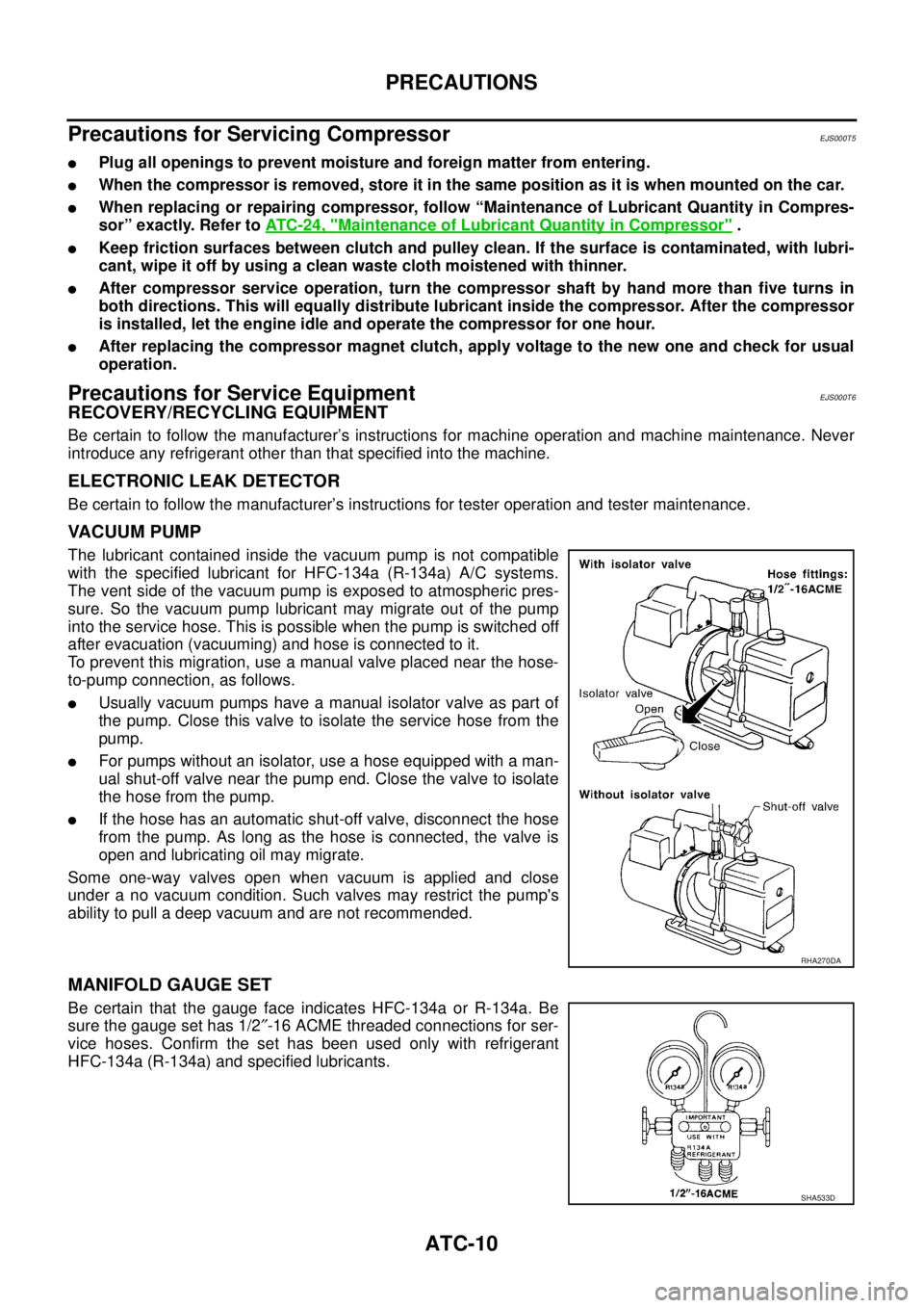
VACUUM PUMP
The lubricant contained inside the vacuum pump is not compatible
with the specified lubricant for HFC-134a (R-134a) A/C systems.
The vent side of the vacuum pump is exposed to atmospheric pres-
sure. So the vacuum pump lubricant may migrate out of the pump
into the service hose. This is possible when the pump is switched off
after evacuation (vacuuming) and hose is connected to it.
To prevent this migration, use a manual valve placed near the hose-
to-pump connection, as follows.
�Usually vacuum pumps have a manual isolator valve as part of
the pump. Close this valve to isolate the service hose from the
pump.
�For pumps without an isolator, use a hose equipped with a man-
ual shut-off valve near the pump end. Close the valve to isolate
the hose from the pump.
�If the hose has an automatic shut-off valve, disconnect the hose
from the pump. As long as the hose is connected, the valve is
open and lubricating oil may migrate.
Some one-way valves open when vacuum is applied and close
under a no vacuum condition. Such valves may restrict the pump's
ability to pull a deep vacuum and are not recommended.
MANIFOLD GAUGE SET
Be certain that the gauge face indicates HFC-134a or R-134a. Be
sure the gauge set has 1/2″-16 ACME threaded connections for ser-
vice hoses. Confirm the set has been used only with refrigerant
HFC-134a (R-134a) and specified lubricants.
RHA270DA
SHA533D
Page 3192 of 4555
ATC-14
PREPARATION
PREPARATIONPFP:00002
Special Service ToolsEJS001F1
WITH GASOLINE ENGINE (CWV-615M COMPRESSOR)
WITH DIESEL ENGINE (DKV-11G COMPRESSOR)
Tool number
Tool nameDescription
KV99106100
Clutch disc wrenchRemoving shaft nut and clutch disc
KV99232340
Clutch disc pullerRemoving clutch disc
KV99106200
Pulley installerInstalling pulley
S-NT232
RJIA0194E
S-NT376
S-NT235
Tool number
Tool nameDescription
KV99231260
Clutch disc wrenchRemoving shaft nut and clutch disc
KV992T0001
Clutch disc pullerRemoving clutch disc
RJIA0475E
RJIA0476E
Page 3193 of 4555

PREPARATION
ATC-15
C
D
E
F
G
H
I
K
L
MA
B
AT C
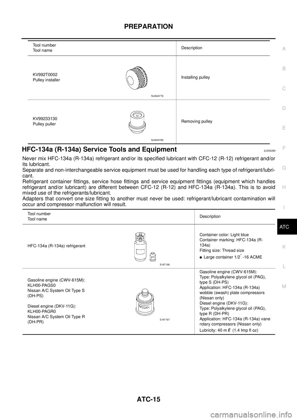
HFC-134a (R-134a) Service Tools and EquipmentEJS00286
Never mix HFC-134a (R-134a) refrigerant and/or its specified lubricant with CFC-12 (R-12) refrigerant and/or
its lubricant.
Separate and non-interchangeable service equipment must be used for handling each type of refrigerant/lubri-
cant.
Refrigerant container fittings, service hose fittings and service equipment fittings (equipment which handles
refrigerant and/or lubricant) are different between CFC-12 (R-12) and HFC-134a (R-134a). This is to avoid
mixed use of the refrigerants/lubricant.
Adapters that convert one size fitting to another must never be used: refrigerant/lubricant contamination will
occur and compressor malfunction will result.
KV992T0002
Pulley installerInstalling pulley
KV99233130
Pulley pullerRemoving pulley Tool number
Tool nameDescription
RJIA0477E
RJIA0478E
Tool number
Tool nameDescription
HFC-134a (R-134a) refrigerantContainer color: Light blue
Container marking: HFC-134a (R-
134a)
Fitting size: Thread size
�Large container 1/2″ -16 ACME
Gasoline engine (CWV-615M):
KLH00-PAGS0
Nissan A/C System Oil Type S
(DH-PS)
Diesel engine (DKV-11G):
KLH00-PAGR0
Nissan A/C System Oil Type R
(DH-PR)Gasoline engine (CWV-615M):
Type: Polyalkylene glycol oil (PAG),
type S (DH-PS)
Application: HFC-134a (R-134a)
wobble (swash) plate compressors
(Nissan only)
Diesel engine (DKV-11G):
Type: Polyalkylene glycol oil (PAG),
type R (DH-PR)
Application: HFC-134a (R-134a) vane
rotary compressors (Nissan only)
Lubricity: 40 m (1.4 Imp fl oz)
S-NT196
S-NT197
Page 3325 of 4555
REFRIGERANT LINES
ATC-147
C
D
E
F
G
H
I
K
L
MA
B
AT C
2. Remove clutch disc using clutch disc puller.
3. Remove snap ring using external snap ring pliers.
4. Position the center pulley puller on the end of the drive shaft,
and remove pulley assembly using any commercially available
pulley puller.
To prevent the pulley groove from being deformed, the puller
claws should be positioned into the edge of the pulley assembly.
RHA399FA
RHA124FA
RHA138E
RHA139E
Page 3327 of 4555

REFRIGERANT LINES
ATC-149
C
D
E
F
G
H
I
K
L
MA
B
AT C
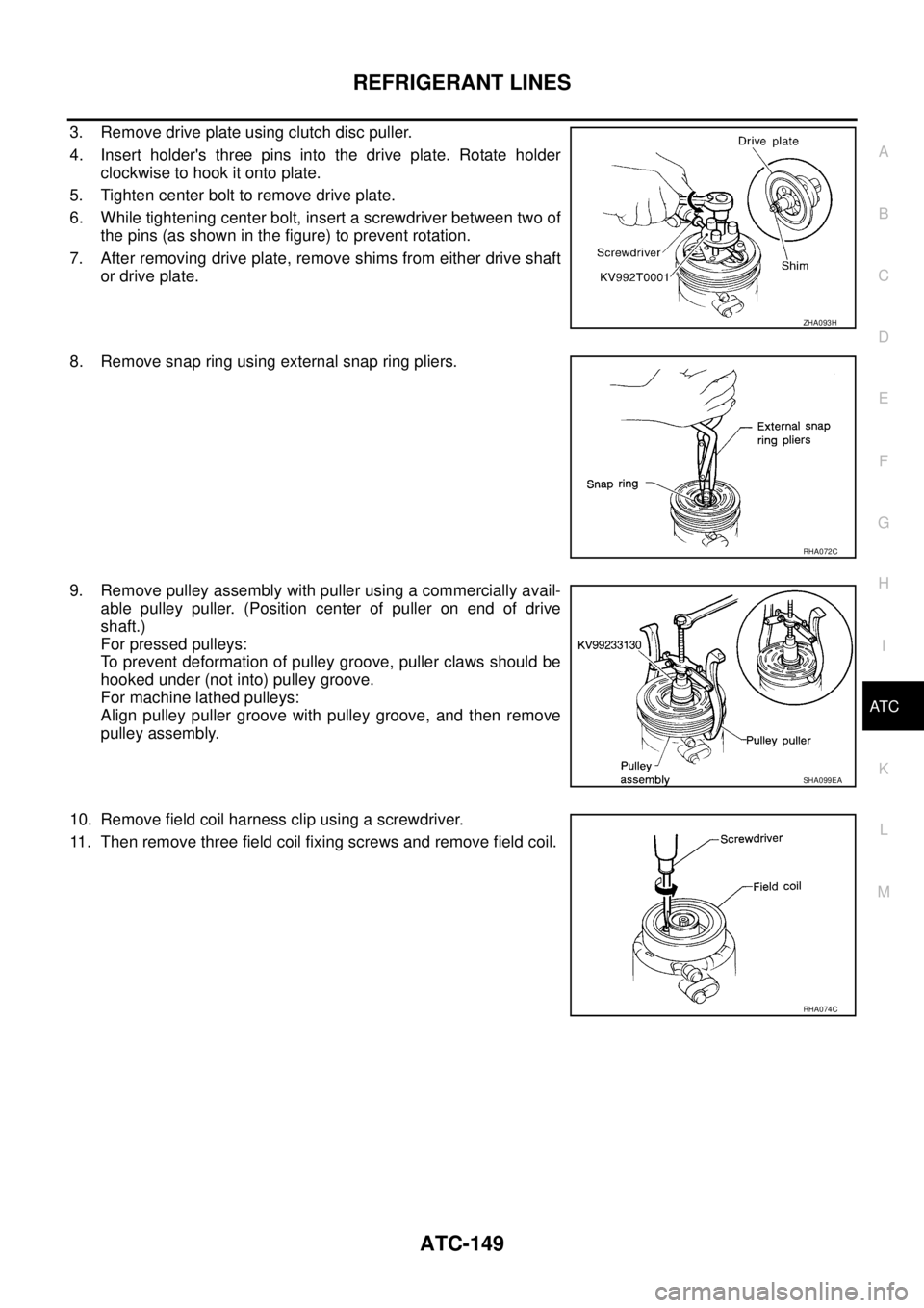
3. Remove drive plate using clutch disc puller.
4. Insert holder's three pins into the drive plate. Rotate holder
clockwise to hook it onto plate.
5. Tighten center bolt to remove drive plate.
6. While tightening center bolt, insert a screwdriver between two of
the pins (as shown in the figure) to prevent rotation.
7. After removing drive plate, remove shims from either drive shaft
or drive plate.
8. Remove snap ring using external snap ring pliers.
9. Remove pulley assembly with puller using a commercially avail-
able pulley puller. (Position center of puller on end of drive
shaft.)
For pressed pulleys:
To prevent deformation of pulley groove, puller claws should be
hooked under (not into) pulley groove.
For machine lathed pulleys:
Align pulley puller groove with pulley groove, and then remove
pulley assembly.
10. Remove field coil harness clip using a screwdriver.
11. Then remove three field coil fixing screws and remove field coil.
ZHA093H
RHA072C
SHA099EA
RHA074C
Page 3328 of 4555
ATC-150
REFRIGERANT LINES
Inspection
Clutch disc
If the contact surface shows signs of damage due to excessive heat,
replace clutch disc and pulley.
Pulley
Check the appearance of the pulley assembly. If contact surface of
pulley shows signs of excessive grooving, replace clutch disc and
pulley. The contact surfaces of the pulley assembly should be
cleaned with a suitable solvent before reinstallation.
Coil
Check coil for loose connection or cracked insulation.
INSTALLATION
With Gasoline Engine (CWV-615M Compressor)
1. Install field coil.
Be sure to align the coil's pin with the hole in the compressor’s
front head.
2. Install field coil harness clip using a screwdriver.
3. Install pulley assembly using installer and a hand press, and
then install snap ring using snap ring pliers.
RJIA0582E
RJIA0583E
RHA142E
RHA143E