Page 248 of 4555
![NISSAN X-TRAIL 2005 Service Repair Manual EM-194
[YD22DDTi]
SECONDARY TIMING CHAIN
�Loosen fixing bolts in reverse order of that shown in the figure
and remove them.
�Remove No. 6, 10 and 11 bolts with the rubber washer as
space is limited](/manual-img/5/57403/w960_57403-247.png "NISSAN X-TRAIL 2005 Service Repair Manual EM-194
[YD22DDTi]
SECONDARY TIMING CHAIN
�Loosen fixing bolts in reverse order of that shown in the figure
and remove them.
�Remove No. 6, 10 and 11 bolts with the rubber washer as
space is limited")
EM-194
[YD22DDTi]
SECONDARY TIMING CHAIN
�Loosen fixing bolts in reverse order of that shown in the figure
and remove them.
�Remove No. 6, 10 and 11 bolts with the rubber washer as
space is limited for pulling them out.
CAUTION:
�While front chain case is removed, cover openings to
prevent entry of foreign material into engine.
�Do not remove two mass dampers on the back of
cover.
5. Set the No. 1 piston to TDC on its compression stroke.
�Turn crankshaft pulley clockwise so that the alignment mark
(punched mark) on each camshaft sprocket is positioned as
shown in the figure.
�No position indicator is provided on crankshaft pulley.
�When installing, color coded links on secondary timing
chain can be used as alignment marks. Marking may not
be necessary for removal; however, make alignment
marks as required because the alignment mark on fuel
pump sprocket may not be easy to see.
6. Remove chain tensioner as follows:
a. Push the plunger of chain tensioner and keep it pressed with a
push pin.
JEM121G
SBIA0189E
SEM515G
JEM124G
Page 254 of 4555
![NISSAN X-TRAIL 2005 Service Repair Manual EM-200
[YD22DDTi]
PRIMARY TIMING CHAIN
REMOVAL
1. Remove engine coolant reservoir tank. Refer to CO-35, "RADIATOR" .
2. Remove charge air cooler. Refer to EM-144, "
Removal and Installation" .
3. Re](/manual-img/5/57403/w960_57403-253.png "NISSAN X-TRAIL 2005 Service Repair Manual EM-200
[YD22DDTi]
PRIMARY TIMING CHAIN
REMOVAL
1. Remove engine coolant reservoir tank. Refer to CO-35, \"RADIATOR\" .
2. Remove charge air cooler. Refer to EM-144, \"
Removal and Installation\" .
3. Re")
EM-200
[YD22DDTi]
PRIMARY TIMING CHAIN
REMOVAL
1. Remove engine coolant reservoir tank. Refer to CO-35, "RADIATOR" .
2. Remove charge air cooler. Refer to EM-144, "
Removal and Installation" .
3. Remove air cleaner and air duct. Refer to EM-142, "
Removal and Installation" .
4. Remove rocker cover. Refer to EM-178, "
Removal and Installation" .
5. Remove RH engine mounting insulator and bracket. Refer to EM-222, "
ENGINE ASSEMBLY" .
6. Pull power steering reservoir tank out of brackets to move power steering piping. Refer to PS-37,
"HYDRAULIC LINE" .
CAUTION:
To avoid removing power steering reservoir tank out of brackets move it with power steering pip-
ing aside.
7. Remove oil pan (upper and lower). Refer to EM-157, "
Removal and Installation" .
8. Remove oil filter bracket. Refer to LU-26, "
OIL FILTER BRACKET" .
9. Remove fuel injector. Refer to EM-167, "
Removal and Installation" .
10. Remove secondary timing chain and associated parts. Refer to EM-193, "
Removal and Installation" .
11. When removing rear chain case, remove camshaft sprockets. Refer to EM-180, "
Removal and Installa-
tion" .
12. Remove crankshaft pulley as follows:
a. Hold crankshaft pulley with the pulley holder (special service
tool).
b. Loosen crankshaft pulley fixing bolt and pull out the bolt approx-
imately 10 mm (0.39 in).
c. Using the pulley puller (special service tool), remove crankshaft
pulley.
�Use two M6 bolts with approx. 60 mm (2.36 in) shank length
for securing crankshaft pulley.
13. Remove oil pump housing.
10. O-ring 11. Chain guide 12. Tension guide
13. Spacer 14. Gasket 15. Front chain case
16. Rubber washer 17. Crankshaft pulley 18. Front oil seal
19. Power steering oil pump cover 20. Oil pump housing 21. Primary timing chain
22. Oil pump drive spacer 23. Crankshaft sprocket 24. Secondary timing chain
25. Rear chain case 26. Power steering oil pump 27. Key
JEM131G
JEM132G
Page 261 of 4555
![NISSAN X-TRAIL 2005 Service Repair Manual PRIMARY TIMING CHAIN
EM-207
[YD22DDTi]
C
D
E
F
G
H
I
J
K
L
MA
EM
a. Apply a continuous bead of liquid gasket with the tube presser
(special service tool: WS39930000) as shown in the figure.
b. Insta](/manual-img/5/57403/w960_57403-260.png "NISSAN X-TRAIL 2005 Service Repair Manual PRIMARY TIMING CHAIN
EM-207
[YD22DDTi]
C
D
E
F
G
H
I
J
K
L
MA
EM
a. Apply a continuous bead of liquid gasket with the tube presser
(special service tool: WS39930000) as shown in the figure.
b. Insta")
PRIMARY TIMING CHAIN
EM-207
[YD22DDTi]
C
D
E
F
G
H
I
J
K
L
MA
EM
a. Apply a continuous bead of liquid gasket with the tube presser
(special service tool: WS39930000) as shown in the figure.
b. Install oil pump drive spacer to crankshaft.
�Install with the front mark (punched mark) facing the front of
the engine.
c. Install O-ring into the groove of rear chain case.
d. Install oil pump housing.
�When installing, align the inner rotor in the direction of the two facing flats of oil pump drive spacer.
�When installing, align the dowel pin with the pin hole.
e. Tighten fixing bolts in numerical order shown in the figure.
f. After tightening all the bolts, re-tighten in the same order.
14. Check gaps on upper oil pan mounting surface.
�Using straightedge and feeler gauge, measure gaps between
the locations of the following parts:
�If the measured value is out of the standard, install again.
15. Install crankshaft pulley as follows:
a. Install crankshaft pulley, taking care not to damage front oil seal.
CAUTION:
Do not tap pulley on the side surface where belt is installed (outer circumference).A : Leave the start and end areas of the bead slightly
protruding from the surface.
B : Apply liquid gasket along upper end surface of oil
pump housing.
JEM144G
JEM145G
JEM133G
Oil pump housing and rear chain case:
Standard : – 0.09 to 0.09 mm (– 0.0035 to 0.0035 in)
Rear chain case and cylinder block:
Standard : – 0.19 to 0.07 mm (– 0.0075 to 0.0028 in)
JEM146G
Page 262 of 4555
EM-208
[YD22DDTi]
PRIMARY TIMING CHAIN
b. Hold crankshaft pulley with the pulley holder (special service
tool).
c. Apply engine oil onto threaded parts of crankshaft pulley bolt
and seating area.
d. Tighten crankshaft pulley fixing bolt.
e. Put an alignment mark on crankshaft pulley that aligns with one
of the punched marks on the bolt.
f. Then turn all bolts 60 degrees clockwise (turn by one notch).
16. Install secondary timing chain and the associated parts. Refer to EM-195, "
INSTALLATION" .
17. Rotate crankshaft pulley in normal direction (clockwise when viewed from engine front) to check for inter-
ference among parts.
18. Install in the reverse order of removal.: 24.5 N·m (2.5 kg-m, 18 ft-lb)
JEM131G
JEM147G
Page 285 of 4555
![NISSAN X-TRAIL 2005 Service Repair Manual CYLINDER BLOCK
EM-231
[YD22DDTi]
C
D
E
F
G
H
I
J
K
L
MA
EM
DISASSEMBLY
1. Remove engine, transaxle and transfer assembly from the vehicle, then separate engine and transaxle
and transfer assembly. R](/manual-img/5/57403/w960_57403-284.png "NISSAN X-TRAIL 2005 Service Repair Manual CYLINDER BLOCK
EM-231
[YD22DDTi]
C
D
E
F
G
H
I
J
K
L
MA
EM
DISASSEMBLY
1. Remove engine, transaxle and transfer assembly from the vehicle, then separate engine and transaxle
and transfer assembly. R")
CYLINDER BLOCK
EM-231
[YD22DDTi]
C
D
E
F
G
H
I
J
K
L
MA
EM
DISASSEMBLY
1. Remove engine, transaxle and transfer assembly from the vehicle, then separate engine and transaxle
and transfer assembly. Refer to EM-222, "
ENGINE ASSEMBLY" .
2. Remove clutch cover and disk. Refer to CL-16, "
CLUTCH DISC, CLUTCH COVER AND FLYWHEEL" .
3. Install engine to engine stand as follows:
a. Remove flywheel.
b. Secure ring gear with the ring gear stopper (special service
tool), then loosen mounting bolts with TORX socket (size: T55,
Commercial Service Tools) and remove them. As an alternative
method hold crankshaft pulley with the pulley holder (special
service tool: KV10109300) to remove flywheel.
CAUTION:
�Do not disassemble flywheel.
�Do not place flywheel with signal plate facing down.
�When handling signal plate, take care not to damage or
scratch it.
�Handle signal plate in a manner that prevents it from
becoming magnetized.
c. Install the engine sub-attachment (special service tool) to the
rear side of cylinder block.
�Align knock pins on cylinder block with pin holes on attach-
ment to install.
NOTE:
Installation bolts are part of engine sub-attachment.
d. Install the engine stand shaft (special service tool).
NOTE:
Use commercially available M12 (0.47 in) mounting bolts and
nuts (4 sets) with strength grade of 9T (minimum).
1. Rear oil seal retainer 2. Cylinder block 3. Oil pressure switch
4. Fuel pump bracket 5. Oil level gauge guide 6. Top ring
7. Second ring 8. Oil ring 9. Oil jet
10. Piston pin 11. Snap ring 12. Piston
13. Main bearing upper 14. Thrust bearing 15. Connecting rod
16. Key 17. Connecting rod bearing 18. Connecting rod cap
19. Connecting rod nut 20. Main bearing lower 21. Crankshaft
22. Main bearing cap bolt 23. Main bearing cap 24. Pilot bushing
25. Flywheel 26. Washer 27. Oil jet relief valve
28. Drain plug 29. Rear oil seal
PBIC2406E
JEM192G
Page 320 of 4555
![NISSAN X-TRAIL 2005 Service Repair Manual EM-266
[YD22DDTi]
SERVICE DATA AND SPECIFICATIONS (SDS)
Bearing Oil Clearance
Unit: mm (in)
Tightening TorqueEBS01FCN
*1: Parts to be tightened in particular orders.
1)-: Order of tightening when ti](/manual-img/5/57403/w960_57403-319.png "NISSAN X-TRAIL 2005 Service Repair Manual EM-266
[YD22DDTi]
SERVICE DATA AND SPECIFICATIONS (SDS)
Bearing Oil Clearance
Unit: mm (in)
Tightening TorqueEBS01FCN
*1: Parts to be tightened in particular orders.
1)-: Order of tightening when ti")
EM-266
[YD22DDTi]
SERVICE DATA AND SPECIFICATIONS (SDS)
Bearing Oil Clearance
Unit: mm (in)
Tightening TorqueEBS01FCN
*1: Parts to be tightened in particular orders.
1)-: Order of tightening when tightening two or more times separately.
Unit: N·m (kg-m, ft-lb)
Unit: N·m (kg-m, in-lb)*2
Connecting rod bearing oil
clearanceStandard 0.031 - 0.061 (0.0012 - 0.0024)
Idler pulley Nut A 35 (3.6, 26)
Alternator Nut C 21.5 (2.2, 16)
Nut D 50.5 (5.2, 37)
Charge air cooler Bracket 22 (2.2, 16)
Charge air cooler cover
7.0 (0.71, 62)*
2
EGR volume control valve 70 (7.1, 52)
EGR cooler Exhaust manifold side 64.5 (6.6, 48)
EGR volume control
valve side70 (7.1, 52)
EGR volume control valve bracket 23.5 (2.4, 17)
Exhaust manifold insulator
7.4 (0.75, 65)*
2
*1 Exhaust manifold31 (3.2, 23)
Turbocharger48.5 (4.9, 36)
Catalyst48.5 (4.9, 36)
Catalyst rear diffuser33.5 (3.4, 25)
Catalyst insulator Catalyst side
7.4 (0.75, 65)*
2
Catalyst rear diffuser
side9.6 (0.97, 85)*
2
Oil pan lower
7 (0.7, 62)*2
Oil pan drain plug34 (3.5, 25)
Oil strainer17 (1.7, 13)
*1 Oil pan upper M6 bolt
7 (0.7, 62)*
2
M8 bolt 21.5 (2.2, 16)
M10 bolt 33.5 (3.4, 25)
Vacuum pump23.5 (2.4, 17)
Cylinder head rear cover M6 bolt
9.7 (0.98, 86) *
2
M8 bolt 17 (1.7, 13)
Injection tube Nozzle side 23.0 (2.3, 17)
Fuel rail side 23.0 (2.3, 17)
Injection tube center23.0 (2.3, 17)
Nozzle support26.2 (2.7, 19)
Spill tube Nozzle side 18.7 (1.9, 14)
Cylinder head side 18.7 (1.9, 14)
Fuel rail57.5 (5.9, 42)
Fuel pump31.4 (3.2, 23)
Fuel pump sprocket39 (4.0, 29)
Page 399 of 4555
![NISSAN X-TRAIL 2005 Service Repair Manual WATER PUMP
CO-43
[YD22DDTi]
C
D
E
F
G
H
I
J
K
L
MA
CO
WAT E R P U MPPFP:21020
Removal and InstallationEBS00BB4
WARNING:
Do not remove radiator cap when the engine is hot. Serious burns could occur](/manual-img/5/57403/w960_57403-398.png "NISSAN X-TRAIL 2005 Service Repair Manual WATER PUMP
CO-43
[YD22DDTi]
C
D
E
F
G
H
I
J
K
L
MA
CO
WAT E R P U MPPFP:21020
Removal and InstallationEBS00BB4
WARNING:
Do not remove radiator cap when the engine is hot. Serious burns could occur")
WATER PUMP
CO-43
[YD22DDTi]
C
D
E
F
G
H
I
J
K
L
MA
CO
WAT E R P U MPPFP:21020
Removal and InstallationEBS00BB4
WARNING:
Do not remove radiator cap when the engine is hot. Serious burns could occur from high pressure
engine coolant escaping from the radiator.
REMOVAL
1. Remove RH engine undercover.
2. Remove drive belt. Refer to EM-140, "
DRIVE BELTS" .
3. Drain engine coolant. Refer to CO-32, "
DRAINING ENGINE COOLANT" .
CAUTION:
Perform when engine is cold.
4. Support the bottom of oil pan (lower) with a floor jack etc, and remove RH engine mounting insulator (front
side of engine). Refer to EM-222, "
ENGINE ASSEMBLY" .
5. Remove water pump pulley.
�Loosen the pulley bolts after fixing the pulley using a screwdriver etc.
6. Remove RH engine mounting bracket.
7. Remove water pump.
�Engine coolant will leak from cylinder block, so have a receptacle ready below.
CAUTION:
�Handle the water pump vane so that it does not contact any other parts.
�Water pump cannot be disassembled and should be replaced as a unit.
1. Gasket 2. Water pump 3. RH engine mounting bracket
4. Water pump pulley
PBIC2384E
Page 400 of 4555
CO-44
[YD22DDTi]
WATER PUMP
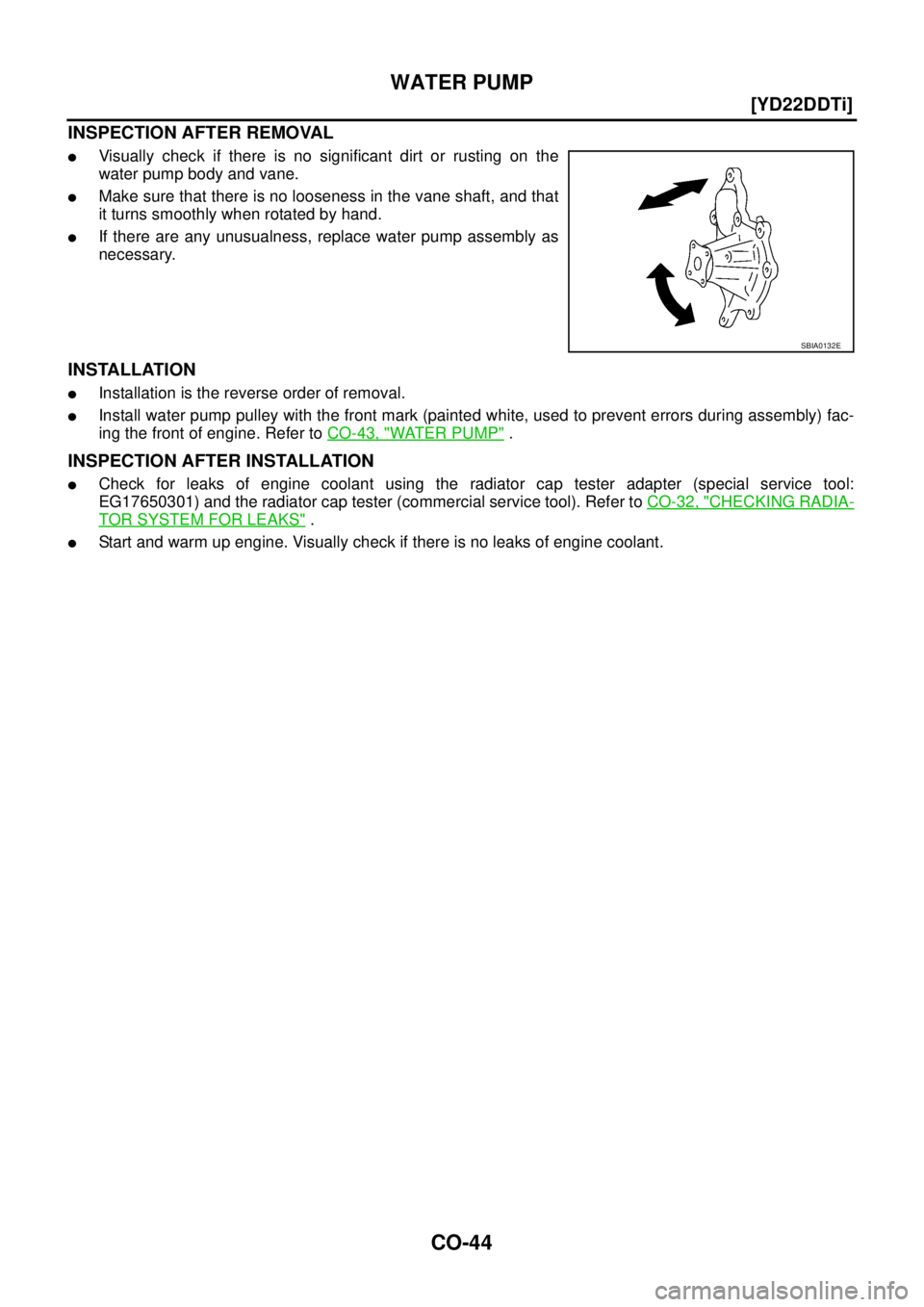
INSPECTION AFTER REMOVAL
�Visually check if there is no significant dirt or rusting on the
water pump body and vane.
�Make sure that there is no looseness in the vane shaft, and that
it turns smoothly when rotated by hand.
�If there are any unusualness, replace water pump assembly as
necessary.
INSTALLATION
�Installation is the reverse order of removal.
�Install water pump pulley with the front mark (painted white, used to prevent errors during assembly) fac-
ing the front of engine. Refer to CO-43, "
WATER PUMP" .
INSPECTION AFTER INSTALLATION
�Check for leaks of engine coolant using the radiator cap tester adapter (special service tool:
EG17650301) and the radiator cap tester (commercial service tool). Refer to CO-32, "
CHECKING RADIA-
TOR SYSTEM FOR LEAKS" .
�Start and warm up engine. Visually check if there is no leaks of engine coolant.
SBIA0132E
![NISSAN X-TRAIL 2005 Service Repair Manual EM-208
[YD22DDTi]
PRIMARY TIMING CHAIN
b. Hold crankshaft pulley with the pulley holder (special service
tool).
c. Apply engine oil onto threaded parts of crankshaft pulley bolt
and seating area.
d.](/manual-img/5/57403/w960_57403-261.png "NISSAN X-TRAIL 2005 Service Repair Manual EM-208
[YD22DDTi]
PRIMARY TIMING CHAIN
b. Hold crankshaft pulley with the pulley holder (special service
tool).
c. Apply engine oil onto threaded parts of crankshaft pulley bolt
and seating area.
d.")