Page 3492 of 4555
PS-30
POWER STEERING OIL PUMP
4. Align dowel pin A on flow control valve A with notch B in side
plate (front) as shown. Install side plate (front) to casing.
5. Install cartridge onto front side plate with smaller slit of cartridge
facing casing.
6. Connect pulley to casing.
CAUTION:
Be careful not to damage drive shaft seal when installing
pulley.
7. Connect rotor to pulley shaft with punch mark on rotor facing
casing.
8. Connect vane to rotor with arc of vane in contact with cartridge.
SGIA0062E
SST497A
SST289A
SST843A
Page 3493 of 4555

POWER STEERING OIL PUMP
PS-31
C
D
E
F
H
I
J
K
L
MA
B
PS
9. Connect rotor snap ring to slit of pulley shaft, using a hammer
and a 10-mm socket.
CAUTION:
� Rotor snap ring is not reusable. Never reuse rotor snap
ring.
�Be careful not to damage rotor and pulley shaft.
�If rotor is damaged, power steering pump assembly must
be replaced.
10. Align dowel pin A on flow control valve A with notch B in side
plate (rear) as shown. Install side plate (rear) to cartridge.
11. Apply DEXRON
TM III or equivalent to body seal. Install it to cas-
ing.
CAUTION:
Body seal is not reusable. Never reuse body seal.
12. Apply DEXRON
TM III or equivalent to side plate inner and outer
seals. Install them to side plate (rear).
CAUTION:
Side plate inner and outer seals are not reusable. Never
reuse side plate inner and outer seals.
13. Fix power steering pump in a vise.
CAUTION:
When fixing pump in a vise, use aluminum plates to protect
steering pump mounting surface.
14. Attach rear body to casing and tighten four mounting bolts diag-
onally to specified torque.
15. Install rear bracket to rear body. Tighten mounting bolts to specified torque.
16. Connect front bracket to casing and tighten mounting bolts (3) to specified torque.
17. Connect inlet connector seal to inlet connector slit. Install inlet connector to casing with attaching bolts.
CAUTION:
Inlet connector seal is not reusable. Never reuse inlet connector seal.
SGIA0063E
SGIA0064E
SGIA0065E
Page 3494 of 4555
PS-32
POWER STEERING OIL PUMP
Removal and Installation (YD22DDTi Engine Model)EGS000AI
1. Remove chain case cover.
2. Revolving crank pulley, set sprocket holder [SST].
3. Fix sprocket holder [SST] with chain cover fixing bolts.
4. Using suitable tool, remove sprocket fixing nut and washer.
CAUTION:
Do not remove Tool while power steering oil pump is
removed.
5. Remove power steering pump fixing bolts, then remove it.
6. Apply Gasket to the installation surface of the engine chain case
cover as shown in the figure before installing the chain case
cover to the engine.
7. Bleed air after installation. Refer to PS-6, "
Air Bleeding Hydrau-
lic System" .
SST884C
SST885C
SST886C
SST890C
Page 3495 of 4555
POWER STEERING OIL PUMP
PS-33
C
D
E
F
H
I
J
K
L
MA
B
PS
Disassembly and Assembly (YD22DDTi Engine Model)EGS000AJ
INSPECTION BEFORE DISASSEMBLY
Disassemble power steering oil pump only when any of following
cases meets.
�If oil leak is found on oil pump.
�Oil pump pulley is deformed or damaged.
�Performance of oil pump is low.
1. Rear bracket 2. Rear body 3. Dowel pin
4. Side plate seal 5. Cam ring 6. Vane
7. Rotor 8. Side plate 9. O-ring (Outer)
10. O-ring (Inner) 11. Front body 12. Drive shaft rear oil sear
13. Drive shaft front oil seal 14. Drive shaft 15. Snap ring
16. O-ring 17. Outlet connector 18. Connector seal
19. Flow control valve 20. Flow control valve spring 21. Inlet connector
22. O-ring 23. Copper washer
SGIA0646E
SST883C
Page 3497 of 4555
POWER STEERING OIL PUMP
PS-35
C
D
E
F
H
I
J
K
L
MA
B
PS
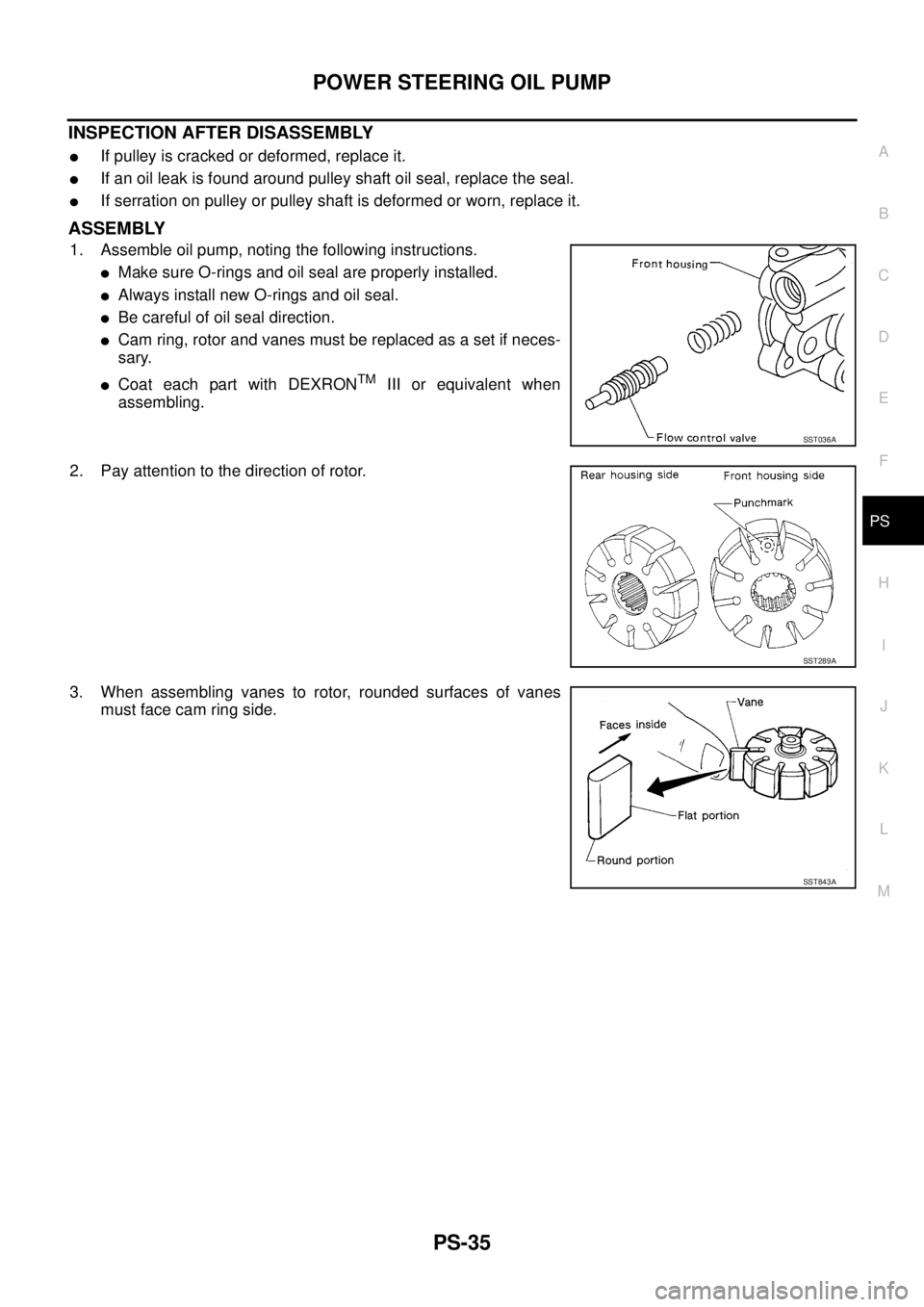
INSPECTION AFTER DISASSEMBLY
�If pulley is cracked or deformed, replace it.
�If an oil leak is found around pulley shaft oil seal, replace the seal.
�If serration on pulley or pulley shaft is deformed or worn, replace it.
ASSEMBLY
1. Assemble oil pump, noting the following instructions.
�Make sure O-rings and oil seal are properly installed.
�Always install new O-rings and oil seal.
�Be careful of oil seal direction.
�Cam ring, rotor and vanes must be replaced as a set if neces-
sary.
�Coat each part with DEXRONTM III or equivalent when
assembling.
2. Pay attention to the direction of rotor.
3. When assembling vanes to rotor, rounded surfaces of vanes
must face cam ring side.
SST036A
SST289A
SST843A
Page 3961 of 4555

SC-1
STARTING & CHARGING SYSTEM
K ELECTRICAL
CONTENTS
C
D
E
F
G
H
I
J
L
M
SECTION SC
A
B
SC
STARTING & CHARGING SYSTEM
PRECAUTIONS .......................................................... 2
Precautions for Supplemental Restraint System
(SRS) “AIR BAG” and “SEAT BELT PRE-TEN-
SIONER” .................................................................. 2
Wiring Diagrams and Trouble Diagnosis .................. 2
PREPARATION ........................................................... 3
Special Service Tools ............................................... 3
BATTERY .................................................................... 4
How to Handle Battery ............................................. 4
METHODS OF PREVENTING OVER-DIS-
CHARGE ............................................................... 4
CHECKING ELECTROLYTE LEVEL .................... 4
SPECIFIC GRAVITY CHECK ............................... 5
Battery Test and Charging Chart .............................. 6
CHART I ................................................................ 6
CHART II ............................................................... 7
A: SLOW CHARGE ............................................... 8
B: STANDARD CHARGE ...................................... 9
C: QUICK CHARGE ............................................. 11
Removal and Installation ........................................ 12
CHARGING SYSTEM ............................................... 13
System Description ................................................ 13
Wiring Diagram — CHARGE — /With Gasoline
Engine .................................................................... 14
Wiring Diagram — CHARGE — /With Diesel Engine ... 15
Trouble Diagnosis .................................................. 16
WITH IC REGULATOR ....................................... 16
MALFUNCTION INDICATOR .............................. 16
Removal and Installation ........................................ 17
REMOVAL (QR ENGINE MODELS) ................... 17
REMOVAL (YD ENGINE MODELS) ................... 17
ALTERNATOR PULLEY INSPECTION (QR ENGINE MODELS) ............................................. 17
INSTALLATION ................................................... 18
Disassembly and Assembly .................................... 19
DISASSEMBLY ................................................... 20
INSPECTION ...................................................... 21
ASSEMBLY ......................................................... 22
STARTING SYSTEM ................................................. 23
System Description ................................................. 23
M/T MODELS ...................................................... 23
A/T MODELS ....................................................... 23
Wiring Diagram — START — /M/T Models ............ 24
Wiring Diagram — START — /A/T Models ............. 25
Trouble Diagnosis ................................................... 26
Removal and Installation ........................................ 27
REMOVAL ........................................................... 27
INSTALLATION ................................................... 27
Disassembly and Assembly .................................... 28
QR ENGINE MODELS ........................................ 28
YD ENGINE MODELS ........................................ 30
Inspection ............................................................... 31
MAGNETIC SWITCH CHECK ............................. 31
PINION/CLUTCH CHECK ................................... 31
BRUSH CHECK .................................................. 31
YOKE CHECK ..................................................... 32
ARMATURE CHECK ........................................... 33
Assembly ................................................................ 34
PINION PROTRUSION LENGTH ADJUST-
MENT .................................................................. 34
SERVICE DATA AND SPECIFICATIONS (SDS) ...... 36
Battery .................................................................... 36
Starter ..................................................................... 36
Alternator ................................................................ 36
Page 3963 of 4555
PREPARATION
SC-3
C
D
E
F
G
H
I
J
L
MA
B
SC
PREPARATIONPFP:00002
Special Service ToolsEKS00ORD
Tool number
Tool nameDescription
KV10118200
Alternator pulley adapterRemoving alternator pulley
PKIA1241E
Page 3977 of 4555

1. Disconnect the battery cable from the negative terminal.
2. Remove drive belt. Refer t")
CHARGING SYSTEM
SC-17
C
D
E
F
G
H
I
J
L
MA
B
SC
Removal and Installation EKS0031A
REMOVAL (QR ENGINE MODELS)
1. Disconnect the battery cable from the negative terminal.
2. Remove drive belt. Refer to EM-13, "
Checking Drive Belts" in EM section.
3. Remove alternator harness mounting bolt, ground mounting
bolt, alternator connector and “B” terminal mounting nut.
4. Remove alternator assembly upward.
5. Remove alternator mounting bolts.
REMOVAL (YD ENGINE MODELS)
1. Disconnect the battery cable from the negative terminal.
2. Remove alternator harness mounting bolt, alternator connector
and “B” terminal mounting nut.
3. Remove alternator and water pump belt. Refer to EM-140,
"Checking Drive Belts" in EM section.
4. Remove alternator bracket mounting bolts and alternator
bracket.
5. Remove alternator mounting bolts.
6. Remove alternator assembly upward.
ALTERNATOR PULLEY INSPECTION (QR ENGINE MODELS)
One-Way Clutch Pulley Check
Fix rotor with inserting a suitable tool rolled with a cloth.
CAUTION:
Be careful not to damage the rotor.
1. Check for locking. (Outer ring is turned clockwise when viewed
from the front.)
�If it rotates in both directions... Replace pulley.
2. Check for dragging. (Outer ring is turned counterclockwise when
viewed from the front.)
�If it locks or unusual resistance is felt... Replace pulley.
PKIA2496E
MEL948N
SKIB0529E
 as shown. Install side plate (front) to casing.
5. Install cartridge onto front side pla")
![NISSAN X-TRAIL 2005 Service Repair Manual PS-32
POWER STEERING OIL PUMP
Removal and Installation (YD22DDTi Engine Model)EGS000AI
1. Remove chain case cover.
2. Revolving crank pulley, set sprocket holder [SST].
3. Fix sprocket holder [SST]](/manual-img/5/57403/w960_57403-3493.png "NISSAN X-TRAIL 2005 Service Repair Manual PS-32
POWER STEERING OIL PUMP
Removal and Installation (YD22DDTi Engine Model)EGS000AI
1. Remove chain case cover.
2. Revolving crank pulley, set sprocket holder [SST].
3. Fix sprocket holder [SST]")
EGS000AJ
INSPECTION BEFORE DISASSEMBLY
Disassemble power steering oil pump only when any of fo")