Page 3979 of 4555
CHARGING SYSTEM
SC-19
C
D
E
F
G
H
I
J
L
MA
B
SC
Disassembly and AssemblyEKS0031B
QR ENGINE MODELS
PKIB7676E
1. Stator 2. Rear bearing 3. Rotor
4. Retainer 5. Front bearing 6. Front cover
7. Pulley 8. Fan guide 9. Labyrinth seal
10. IC voltage regulator assembly 11. Diode assembly 12. Rear cover
13. Terminal assembly 14. Through-bolt
Page 3980 of 4555
SC-20
CHARGING SYSTEM
YD ENGINE MODELS
DISASSEMBLY
Rear Cover
1. Remove through-bolt (4).
2. Remove rear cover.
NOTE:
Rear cover may be hard to remove because a ring is used to
lock outer race of rear bearing. To facilitate removal of rear
cover, heat just bearing box section with a 200 W soldering iron
until the temperature increases by about 30 °C.
CAUTION:
Never use a heat gun, as it can damage diode assembly.
PKIB9810E
1. Rear bearing 2. Rotor 3. Retainer
4. Front bearing 5. Through-bolt 6. Front cover
7. Pulley 8. Pulley nut 9. Stator
10. IC voltage regulator assembly 11. Diode assembly 12. Rear cover
13. B terminal
SEL032Z
Page 3981 of 4555
CHARGING SYSTEM
SC-21
C
D
E
F
G
H
I
J
L
MA
B
SC
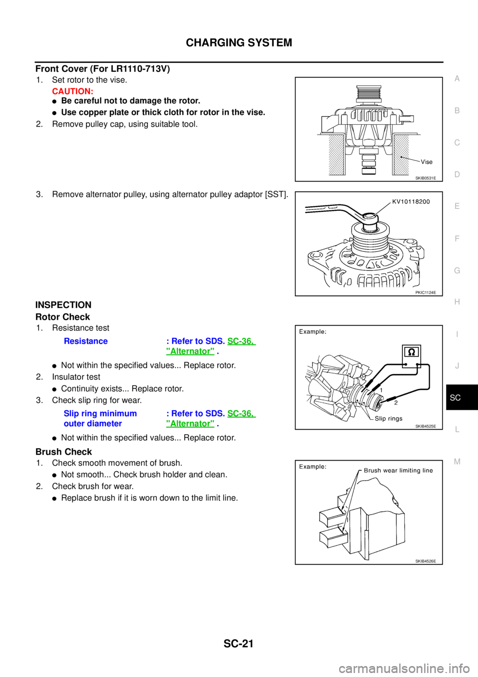
Front Cover (For LR1110-713V)
1. Set rotor to the vise.
CAUTION:
�Be careful not to damage the rotor.
�Use copper plate or thick cloth for rotor in the vise.
2. Remove pulley cap, using suitable tool.
3. Remove alternator pulley, using alternator pulley adaptor [SST].
INSPECTION
Rotor Check
1. Resistance test
�Not within the specified values... Replace rotor.
2. Insulator test
�Continuity exists... Replace rotor.
3. Check slip ring for wear.
�Not within the specified values... Replace rotor.
Brush Check
1. Check smooth movement of brush.
�Not smooth... Check brush holder and clean.
2. Check brush for wear.
�Replace brush if it is worn down to the limit line.
SKIB0531E
PKIC1124E
Resistance : Refer to SDS. SC-36,
"Alternator" .
Slip ring minimum
outer diameter: Refer to SDS. SC-36,
"Alternator" .SKIB4525E
SKIB4526E
Page 4525 of 4555

MA-29
C
D
E
F
G
H
I
J
K
MA
B
MA
ENGINE MAINTENANCE (YD22DDTI) PFP:00100
Checking Drive BeltsELS000CC
�Before inspecting the engine, make sure the engine has cooled
down")
ENGINE MAINTENANCE (YD22DDTI)
MA-29
C
D
E
F
G
H
I
J
K
MA
B
MA
ENGINE MAINTENANCE (YD22DDTI) PFP:00100
Checking Drive BeltsELS000CC
�Before inspecting the engine, make sure the engine has cooled
down; wait approximately 30 minutes after the engine has been
stopped.
�Visually inspect all belts for wear, damage or cracks on contact-
ing surfaces and edge areas.
�When measuring deflection, apply 98 N (10 kg, 22 lb) at the
marked point ( ).
CAUTION:
�When checking belt deflection immediately after installa-
tion, first adjust it to the specified value. Then, after turn-
ing the crankshaft two turns or more, re-adjust to the
specified value to avoid variation in deflection between
pulleys.
�Tighten idler pulley lock nut by hand and measure deflection without looseness.
Belt Deflection:
*: When engine is cold.
Tension AdjustmentELS000K5
Adjust belts with the parts shown below.
CAUTION:
�When a new belt is installed as a replacement, adjust it to the specified value under “New” value
because of insufficient adaptability with pulley grooves.
�If the belt deflection of the current belt is out of the “Limit for re-adjusting”, adjust to the
“Adjusted” value.
�When checking belt deflection immediately after installation, first adjust it to the specified value.
Then, after turning crankshaft two turns or more, re-adjust it to the specified value to avoid varia-
tion in deflection between pulleys.
�Make sure the belts are fully fitted into the pulley grooves during installation.
�Handle with care to avoid smearing the belts with engine oil or engine coolant etc.
�Do not twist or bend the belts with strong force.
PBIC1251E
Applied beltBelt deflection with 98 N (10 kg, 22 lb) force applied* mm (in)
New Adjusted Limit for re-adjusting
A/C compressor belt 4 - 5 (0.16 - 0.20) 6 - 7 (0.24 - 0.28) 8.5 (0.335)
Alternator and water pump belt 9.0 - 10.5 (0.354 - 0.413) 11.0 - 12.5 (0.433 - 0.492) 16.5 (0.650)
Applied belt Belt adjustment method
A/C compressor belt Adjusting bolt on idler pulley
Alternator and water pump belt Adjusting bolt on alternator
Page 4526 of 4555

A/C COMPRESSOR BELT
1. Remove RH engine undercover.
2. Loosen idler pulley lock nut (A).
3. Turn adjusting bolt (B) to adjust.
�Refer to MA-29, \"Checking Drive Be")
MA-30
ENGINE MAINTENANCE (YD22DDTI)
A/C COMPRESSOR BELT
1. Remove RH engine undercover.
2. Loosen idler pulley lock nut (A).
3. Turn adjusting bolt (B) to adjust.
�Refer to MA-29, "Checking Drive Belts" .
4. Tighten lock nut (A).
ALTERNATOR AND WATER PUMP BELT
1. Loosen adjusting lock nut (C).
2. Loosen alternator fixing bolts (D) (each on front and rear).
3. Turn adjusting bolt (E) to adjust.
�Refer to MA-29, "Tension Adjustment" .
4. Tighten nut (C) and bolt (D) in this order.
Changing Engine CoolantELS000CD
WARNING:
�To avoid being scalded, never change the engine coolant when the engine is hot.
�Wrap a thick cloth around cap and carefully remove the cap. First, turn the cap a quarter of a turn
to release built-up pressure. Then turn the cap all the way.
DRAINING ENGINE COOLANT
1. Remove engine undercover.
2. Open radiator drain plug at the bottom of radiator, and remove
radiator cap.
CAUTION:
�Be careful not to allow engine coolant to contact drive
belts.
�Cover the exhaust tube heat shield to prevent from
splashing engine coolant.Nut A:
: 35 N-m (3.6 kg-m, 26 ft-lb)
PBIC1252E
Nut C:
: 21.5 N-m (2.2 kg-m, 16 ft-lb)
Bolt D:
: 50.5 N-m (5.2 kg-m, 37 ft-lb)
PBIC0236E

.
2. Remove rear cover.
NOTE:
Rear cover may be hard to remove because a ring is used to
lock outer race of re")