Page 2974 of 4555
FSU-10
TRANSVERSE LINK
TRANSVERSE LINK PFP:54500
Removal and InstallationEES00076
REMOVAL
1. Remove steering knuckle from transverse link. Refer to FAX-7, "REMOVAL" .
2. Remove mounting nuts and washers on lower portion of stabilizer connecting rod.
3. Slightly loosen transverse link mounting bolts.
4. Remove transverse link mounting bolts and nuts, and remove transverse link from suspension member.
INSPECTION AFTER REMOVAL
Visual Inspection
Check transverse link and bushing for deformation, cracks, and other damage. Replace the entire transverse
link assembly if cracks, deformation or any other damage is found.
Ball Joint Inspection
CAUTION:
Before measurement, move the ball joint at least ten times by hand to check for smooth movement.
Swing Torque Inspection
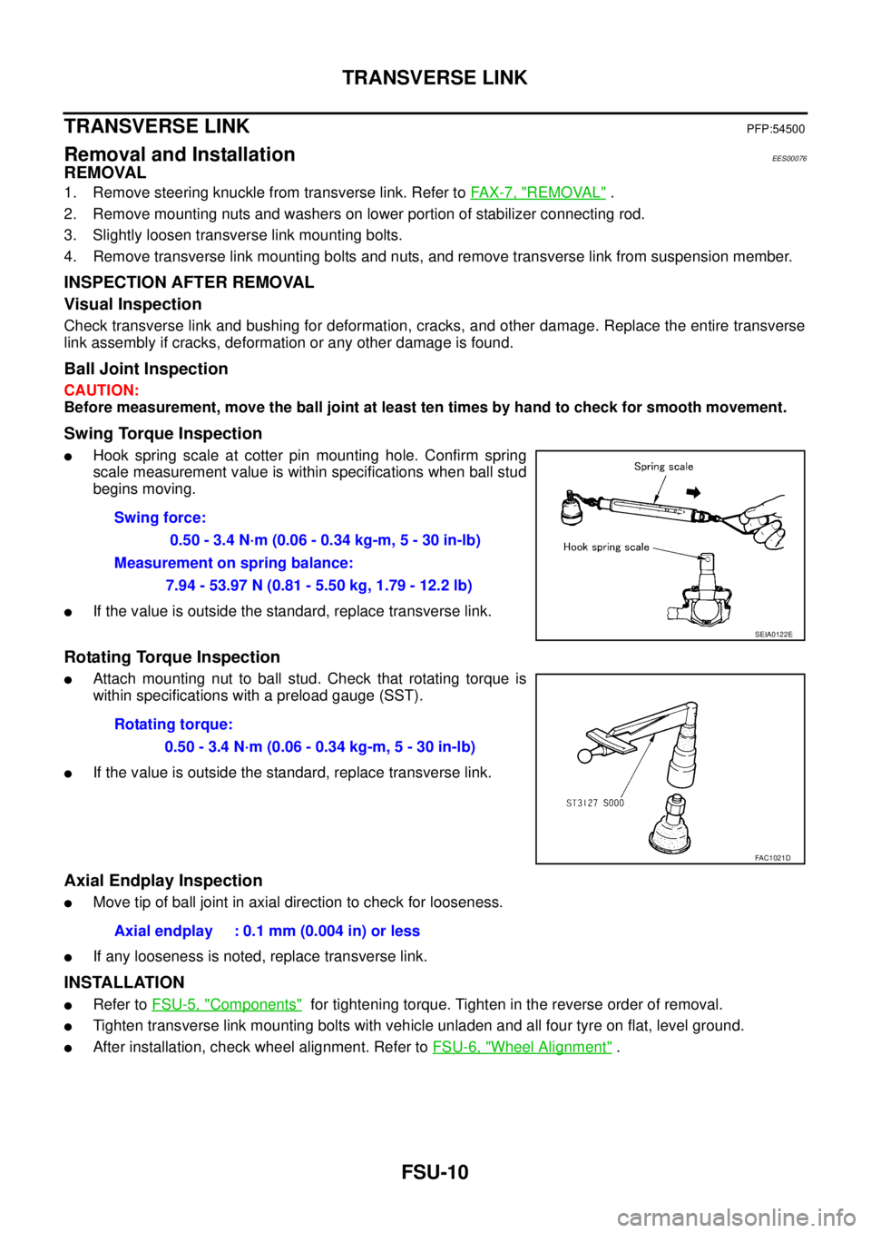
�Hook spring scale at cotter pin mounting hole. Confirm spring
scale measurement value is within specifications when ball stud
begins moving.
�If the value is outside the standard, replace transverse link.
Rotating Torque Inspection
�Attach mounting nut to ball stud. Check that rotating torque is
within specifications with a preload gauge (SST).
�If the value is outside the standard, replace transverse link.
Axial Endplay Inspection
�Move tip of ball joint in axial direction to check for looseness.
�If any looseness is noted, replace transverse link.
INSTALLATION
�Refer to FSU-5, "Components" for tightening torque. Tighten in the reverse order of removal.
�Tighten transverse link mounting bolts with vehicle unladen and all four tyre on flat, level ground.
�After installation, check wheel alignment. Refer to FSU-6, "Wheel Alignment" . Swing force:
0.50 - 3.4 N·m (0.06 - 0.34 kg-m, 5 - 30 in-lb)
Measurement on spring balance:
7.94 - 53.97 N (0.81 - 5.50 kg, 1.79 - 12.2 lb)
SEIA0122E
Rotating torque:
0.50 - 3.4 N·m (0.06 - 0.34 kg-m, 5 - 30 in-lb)
FAC1021D
Axial endplay : 0.1 mm (0.004 in) or less
Page 2976 of 4555
FSU-12
FRONT SUSPENSION MEMBER
FRONT SUSPENSION MEMBERPFP:54401
Removal and InstallationEES00078
REMOVAL
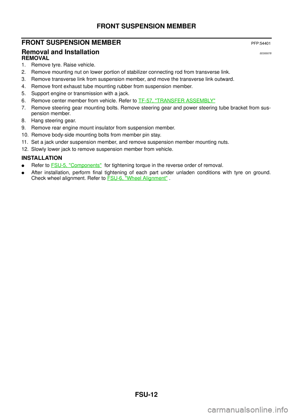
1. Remove tyre. Raise vehicle.
2. Remove mounting nut on lower portion of stabilizer connecting rod from transverse link.
3. Remove transverse link from suspension member, and move the transverse link outward.
4. Remove front exhaust tube mounting rubber from suspension member.
5. Support engine or transmission with a jack.
6. Remove center member from vehicle. Refer to TF-57, "
TRANSFER ASSEMBLY"
7. Remove steering gear mounting bolts. Remove steering gear and power steering tube bracket from sus-
pension member.
8. Hang steering gear.
9. Remove rear engine mount insulator from suspension member.
10. Remove body-side mounting bolts from member pin stay.
11. Set a jack under suspension member, and remove suspension member mounting nuts.
12. Slowly lower jack to remove suspension member from vehicle.
INSTALLATION
�Refer to FSU-5, "Components" for tightening torque in the reverse order of removal.
�After installation, perform final tightening of each part under unladen conditions with tyre on ground.
Check wheel alignment. Refer to FSU-6, "
Wheel Alignment" .
Page 2977 of 4555
SERVICE DATA AND SPECIFICATIONS (SDS)
FSU-13
C
D
F
G
H
I
J
K
L
MA
B
FSU
SERVICE DATA AND SPECIFICATIONS (SDS)PFP:00030
General SpecificationEES000J6
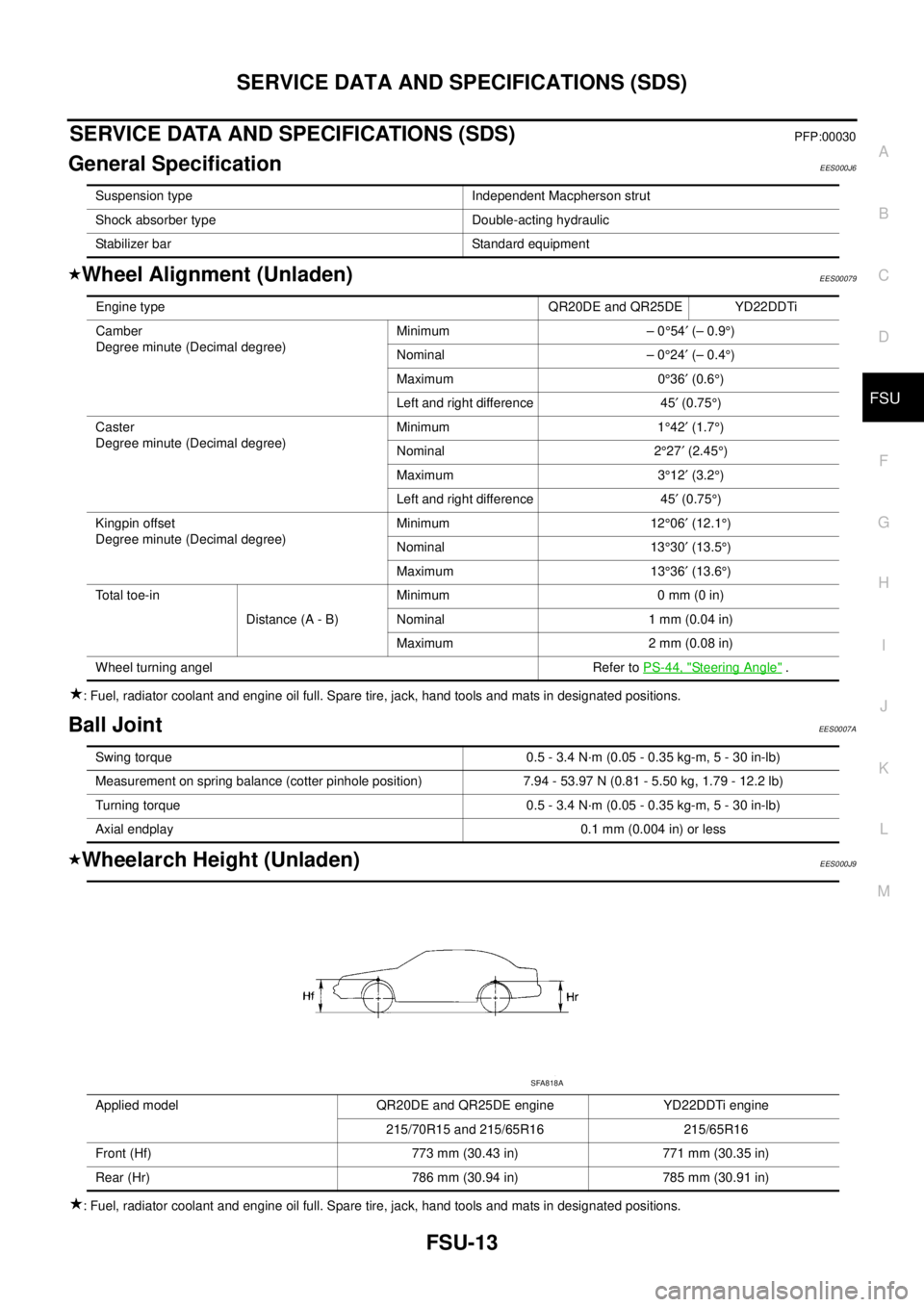
Wheel Alignment (Unladen)EES00079
: Fuel, radiator coolant and engine oil full. Spare tire, jack, hand tools and mats in designated positions.
Ball JointEES0007A
Wheelarch Height (Unladen)EES000J9
: Fuel, radiator coolant and engine oil full. Spare tire, jack, hand tools and mats in designated positions.Suspension type Independent Macpherson strut
Shock absorber type Double-acting hydraulic
Stabilizer bar Standard equipment
Engine type QR20DE and QR25DE YD22DDTi
Camber
Degree minute (Decimal degree)Minimum – 0°54′ (– 0.9°)
Nominal – 0°24′ (– 0.4°)
Maximum 0°36′ (0.6°)
Left and right difference 45′ (0.75°)
Caster
Degree minute (Decimal degree)Minimum 1°42′ (1.7°)
Nominal 2°27′ (2.45°)
Maximum 3°12′ (3.2°)
Left and right difference 45′ (0.75°)
Kingpin offset
Degree minute (Decimal degree)Minimum 12°06′ (12.1°)
Nominal 13°30′ (13.5°)
Maximum 13°36′ (13.6°)
Total toe-in
Distance (A - B)Minimum 0 mm (0 in)
Nominal 1 mm (0.04 in)
Maximum 2 mm (0.08 in)
Wheel turning angel Refer to PS-44, "
Steering Angle" .
Swing torque 0.5 - 3.4 N·m (0.05 - 0.35 kg-m, 5 - 30 in-lb)
Measurement on spring balance (cotter pinhole position) 7.94 - 53.97 N (0.81 - 5.50 kg, 1.79 - 12.2 lb)
Turning torque 0.5 - 3.4 N·m (0.05 - 0.35 kg-m, 5 - 30 in-lb)
Axial endplay 0.1 mm (0.004 in) or less
Applied model QR20DE and QR25DE engine YD22DDTi engine
215/70R15 and 215/65R16 215/65R16
Front (Hf) 773 mm (30.43 in) 771 mm (30.35 in)
Rear (Hr) 786 mm (30.94 in) 785 mm (30.91 in)
SFA818A
Page 2982 of 4555
RSU-4
NOISE, VIBRATION AND HARSHNESS (NVH) TROUBLESHOOTING
NOISE, VIBRATION AND HARSHNESS (NVH) TROUBLESHOOTINGPFP:00003
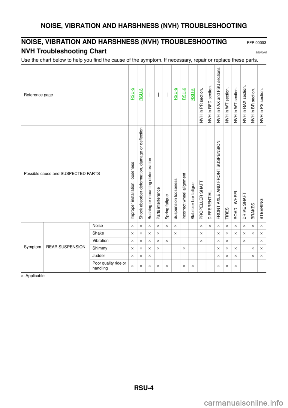
NVH Troubleshooting ChartEES000IE
Use the chart below to help you find the cause of the symptom. If necessary, repair or replace these parts.
×: ApplicableReference page
RSU-5RSU-8—
—
—
RSU-5 RSU-6RSU-5
NVH in PR section.
NVH in RFD section.
NVH in FAX and FSU sections.
NVH in WT section.
NVH in WT section.
NVH in RAX section.
NVH in BR section.
NVH in PS section.
Possible cause and SUSPECTED PARTS
Improper installation, looseness
Shock absorber deformation, damage or deflection
Bushing or mounting deterioration
Parts interference
Spring fatigue
Suspension looseness
Incorrect wheel alignment
Stabilizer bar fatigue
PROPELLER SHAFT
DIFFERENTIAL
FRONT AXLE AND FRONT SUSPENSION
TIRES
ROAD WHEEL
DRIVE SHAFT
BRAKES
STEERING
Symptom REAR SUSPENSIONNoise×××××× ××××××××
Shake×××× × × ××××××
Vibration××××× × ×× × ×
Shimmy×××× × ××× ××
Judder ××× ××× ××
Poor quality ride or
handling××××× ×× ×××
Page 2994 of 4555

WT-2
NOISE, VIBRATION AND HARSHNESS (NVH) TROUBLESHOOTING
NOISE, VIBRATION AND HARSHNESS (NVH) TROUBLESHOOTINGPFP:00003
NVH Troubleshooting ChartEES000J1
Use the chart below to help you find the cause of the symptom. If necessary, repair or replace these parts.
×: ApplicableReference page
WT-3—
—
—
—
—
—
NVH in PR section.
NVH in RFD section.
NVH in FAX and FSU sections.
NVH in RAX and RSU sections.
Refer to TYRES in this chart.
Refer to ROAD WHEEL in this chart.
NVH in RAX section.
NVH in BR section.
NVH in PS section.
Possible cause and SUSPECTED PARTS
Out-of-round
Imbalance
Incorrect tyre pressure
Uneven tyre wear
Deformation or damage
Non-uniformity
Incorrect tyre size
PROPELLER SHAFT
DIFFERENTIAL
FRONT AXLE AND FRONT SUSPENSION
REAR AXLE AND REAR SUSPENSION
TYRES
ROAD WHEELS
DRIVE SHAFT
BRAKE
STEERING
SymptomTYRESNoise×××××× ×××× ××××
Shake××××× ×× ×× ××××
Vibration×××××××
Shimmy××××××× ×× × ××
Judder××××× × ×× × ××
Poor quality ride
or handling××××× × ×× ×
ROAD WHEELNoise×× × ××××× ×××
Shake×× × × ××× ×××
Shimmy, Judder×× × ××× ××
Poor quality ride
or handling×× × ×××
Page 3003 of 4555
NOISE, VIBRATION AND HARSHNESS (NVH) TROUBLESHOOTING
BR-5
C
D
E
G
H
I
J
K
L
MA
B
BR
NOISE, VIBRATION AND HARSHNESS (NVH) TROUBLESHOOTINGPFP:00003
NVH Troubleshooting ChartEFS000TK
Use the chart below to help you find the cause of the symptom. If necessary, repair or replace these parts.
X: ApplicableReference page
BR-27
, BR-32
BR-27
, BR-32
.
BR-27
, BR-32—
—
BR-30, BR-35—
—
—
BR-30, BR-36—
NVH in PR section
NVH in RFD section
NVH in FAX, RAX and FSU, RSU section
NVH in WT section
NVH in WT section
NVH in RAX section
NVH in PS section
Possible cause and
SUSPECTED PARTS
Pads - damaged
Pads - uneven wear
Shims damaged
Rotor imbalance
Rotor damage
Rotor runout
Rotor deformation
Rotor deflection
Rotor rust
Rotor thickness variation
Drum out of round
PROPELLER SHAFT
DIFFERENTIAL
AXLE AND SUSPENSION
TYRES
ROAD WHEEL
DRIVE SHAFT
STEERING
Symptom BRAKENoise××× ×× ×××
××
Shake×××××
××
Shimmy, Judder××××××× ××× ×
Page 3005 of 4555
BRAKE PEDAL
BR-7
C
D
E
G
H
I
J
K
L
MA
B
BR
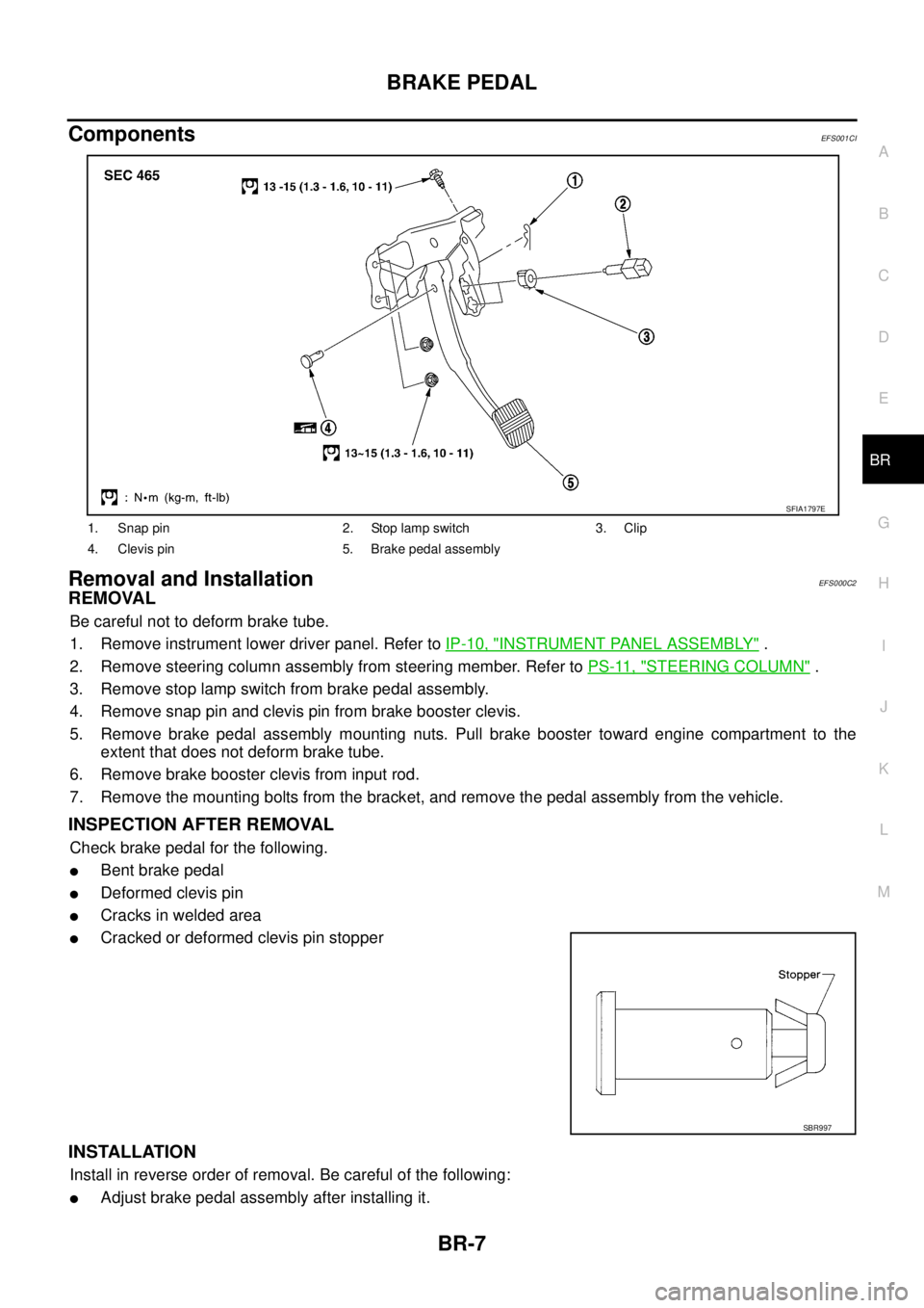
ComponentsEFS001CI
Removal and InstallationEFS000C2
REMOVAL
Be careful not to deform brake tube.
1. Remove instrument lower driver panel. Refer to IP-10, "
INSTRUMENT PANEL ASSEMBLY" .
2. Remove steering column assembly from steering member. Refer to PS-11, "
STEERING COLUMN" .
3. Remove stop lamp switch from brake pedal assembly.
4. Remove snap pin and clevis pin from brake booster clevis.
5. Remove brake pedal assembly mounting nuts. Pull brake booster toward engine compartment to the
extent that does not deform brake tube.
6. Remove brake booster clevis from input rod.
7. Remove the mounting bolts from the bracket, and remove the pedal assembly from the vehicle.
INSPECTION AFTER REMOVAL
Check brake pedal for the following.
�Bent brake pedal
�Deformed clevis pin
�Cracks in welded area
�Cracked or deformed clevis pin stopper
INSTALLATION
Install in reverse order of removal. Be careful of the following:
�Adjust brake pedal assembly after installing it.
1. Snap pin 2. Stop lamp switch 3. Clip
4. Clevis pin 5. Brake pedal assembly
SFIA1797E
SBR997
Page 3027 of 4555
FRONT DISC BRAKE
BR-29
C
D
E
G
H
I
J
K
L
MA
B
BR
INSTALLATION
CAUTION:
�Refill with new brake fluid “DOT 3” or “DOT 4”.
�Never reuse drained brake fluid.
1. Install disc rotor.
2. Install caliper assembly. Tighten mounting bolts to the specified torque.
CAUTION:
Before installing caliper assembly, wipe brake fluid and grease on steering knuckle washer seats
and caliper assembly mounting surface.
3. Connect brake hose to caliper assembly and tighten union bolts to the specified torque.
CAUTION:
�Do not reuse copper washer for union bolts.
�Securely assemble brake hose to protrusions on cylinder body.
4. Bleed air. Refer to BR-9, "
Bleeding Brake System" .
Caliper Disassembly and Assembly EFS000CK
DISASSEMBLY
WARNING:
Be careful not to pinch your fingers in the piston.
CAUTION:
Be careful not to damage the cylinder inner wall.
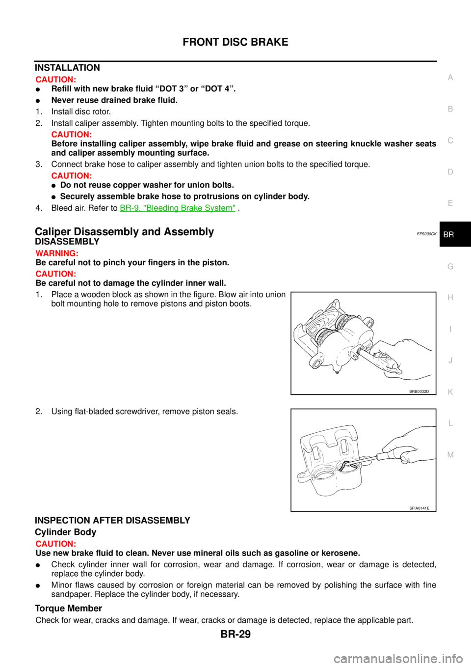
1. Place a wooden block as shown in the figure. Blow air into union
bolt mounting hole to remove pistons and piston boots.
2. Using flat-bladed screwdriver, remove piston seals.
INSPECTION AFTER DISASSEMBLY
Cylinder Body
CAUTION:
Use new brake fluid to clean. Never use mineral oils such as gasoline or kerosene.
�Check cylinder inner wall for corrosion, wear and damage. If corrosion, wear or damage is detected,
replace the cylinder body.
�Minor flaws caused by corrosion or foreign material can be removed by polishing the surface with fine
sandpaper. Replace the cylinder body, if necessary.
To r q u e M e m b e r
Check for wear, cracks and damage. If wear, cracks or damage is detected, replace the applicable part.
BRB0032D
SFIA0141E