Page 2854 of 4555
TF-50
TROUBLE DIAGNOSIS FOR SYMPTOMS
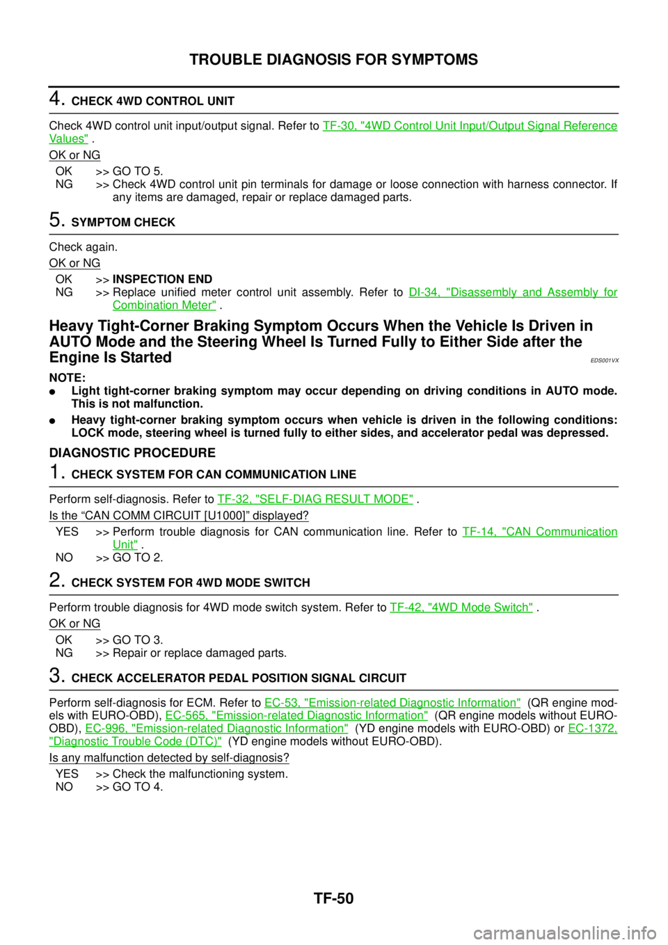
4. CHECK 4WD CONTROL UNIT
Check 4WD control unit input/output signal. Refer to TF-30, "
4WD Control Unit Input/Output Signal Reference
Va l u e s" .
OK or NG
OK >> GO TO 5.
NG >> Check 4WD control unit pin terminals for damage or loose connection with harness connector. If
any items are damaged, repair or replace damaged parts.
5. SYMPTOM CHECK
Check again.
OK or NG
OK >>INSPECTION END
NG >> Replace unified meter control unit assembly. Refer to DI-34, "
Disassembly and Assembly for
Combination Meter" .
Heavy Tight-Corner Braking Symptom Occurs When the Vehicle Is Driven in
AUTO Mode and the Steering Wheel Is Turned Fully to Either Side after the
Engine Is Started
EDS001VX
NOTE:
�Light tight-corner braking symptom may occur depending on driving conditions in AUTO mode.
This is not malfunction.
�Heavy tight-corner braking symptom occurs when vehicle is driven in the following conditions:
LOCK mode, steering wheel is turned fully to either sides, and accelerator pedal was depressed.
DIAGNOSTIC PROCEDURE
1. CHECK SYSTEM FOR CAN COMMUNICATION LINE
Perform self-diagnosis. Refer to TF-32, "
SELF-DIAG RESULT MODE" .
Is the
“CAN COMM CIRCUIT [U1000]” displayed?
YES >> Perform trouble diagnosis for CAN communication line. Refer to TF-14, "CAN Communication
Unit" .
NO >> GO TO 2.
2. CHECK SYSTEM FOR 4WD MODE SWITCH
Perform trouble diagnosis for 4WD mode switch system. Refer to TF-42, "
4WD Mode Switch" .
OK or NG
OK >> GO TO 3.
NG >> Repair or replace damaged parts.
3. CHECK ACCELERATOR PEDAL POSITION SIGNAL CIRCUIT
Perform self-diagnosis for ECM. Refer to EC-53, "
Emission-related Diagnostic Information" (QR engine mod-
els with EURO-OBD), EC-565, "
Emission-related Diagnostic Information" (QR engine models without EURO-
OBD), EC-996, "
Emission-related Diagnostic Information" (YD engine models with EURO-OBD) or EC-1372,
"Diagnostic Trouble Code (DTC)" (YD engine models without EURO-OBD).
Is any malfunction detected by self-diagnosis?
YES >> Check the malfunctioning system.
NO >> GO TO 4.
Page 2884 of 4555
PR-2
NOISE, VIBRATION AND HARSHNESS (NVH) TROUBLESHOOTING
NOISE, VIBRATION AND HARSHNESS (NVH) TROUBLESHOOTINGPFP:00003
NVH Troubleshooting ChartEDS0027A
Use the chart below to help you find the cause of the symptom. If necessary, repair or replace these parts.
×: ApplicableReference page
—
PR-6—
—
—
PR-3—
NVH in RFD section
NVH in FAX, RAX, FSU, and RSU section
NVH in WT section
NVH in WT section
NVH in FAX and RAX section
NVH in BR section
NVH in PS section
Possible cause and SUSPECTED PARTS
Uneven rotating torque
Center bearing improper installation
Excessive center bearing axial end play
Center bearing mounting (insulator) cracks, damage or deterioration
Excessive joint angle
Rotation imbalance
Excessive runout
DIFFERENTIAL
AXLE AND SUSPENSION
TIRES
ROAD WHEEL
DRIVE SHAFT
BRAKES
STEERING
SymptomNoise××××××××××××××
Shake× × ××××××
Vibration××××××× ×× × ×
Page 2896 of 4555
RFD-6
NOISE, VIBRATION AND HARSHNESS (NVH) TROUBLESHOOTING
NOISE, VIBRATION AND HARSHNESS (NVH) TROUBLESHOOTINGPFP:00003
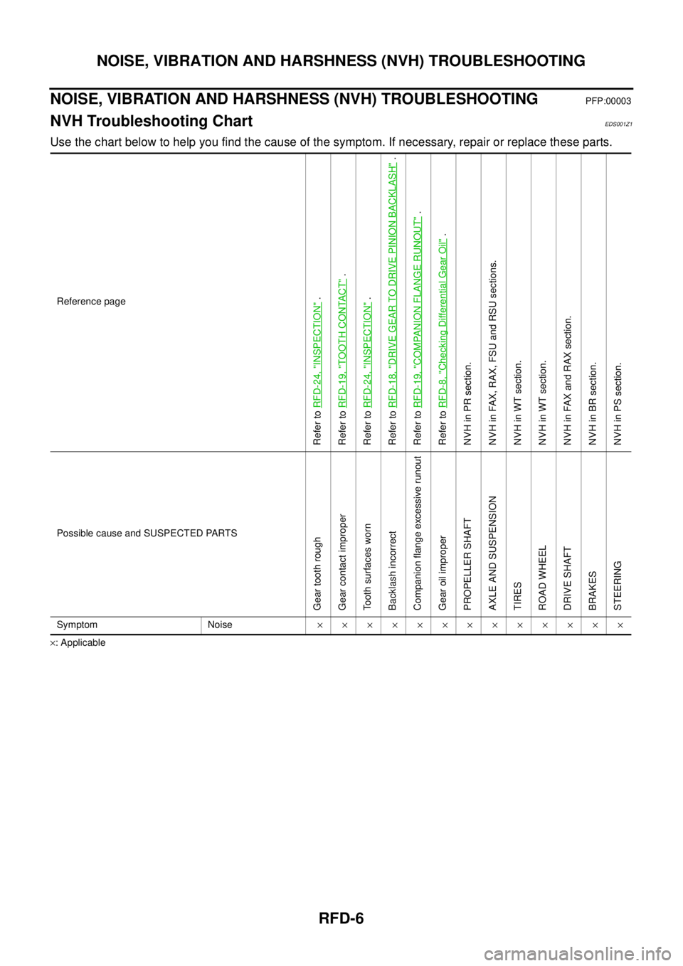
NVH Troubleshooting ChartEDS001Z1
Use the chart below to help you find the cause of the symptom. If necessary, repair or replace these parts.
×: ApplicableReference page
Refer to RFD-24, "
INSPECTION
" .
Refer to RFD-19, "
TOOTH CONTACT
" .
Refer to RFD-24, "
INSPECTION
" .
Refer to RFD-18, "
DRIVE GEAR TO DRIVE PINION BACKLASH
" .
Refer to RFD-19, "
COMPANION FLANGE RUNOUT
" .
Refer to RFD-8, "
Checking Differential Gear Oil
" .
NVH in PR section.
NVH in FAX, RAX, FSU and RSU sections.
NVH in WT section.
NVH in WT section.
NVH in FAX and RAX section.
NVH in BR section.
NVH in PS section.
Possible cause and SUSPECTED PARTS
Gear tooth rough
Gear contact improper
Tooth surfaces worn
Backlash incorrect
Companion flange excessive runout
Gear oil improper
PROPELLER SHAFT
AXLE AND SUSPENSION
TIRES
ROAD WHEEL
DRIVE SHAFT
BRAKES
STEERING
Symptom Noise×××××××××××××
Page 2930 of 4555
FAX-6
NOISE, VIBRATION AND HARSHNESS (NVH) TROUBLESHOOTING
NOISE, VIBRATION AND HARSHNESS (NVH) TROUBLESHOOTINGPFP:00003
NVH Troubleshooting ChartEDS00127
Use the chart below to help you find the cause of the symptom. If necessary, repair or replace these parts.
×: ApplicableReference page
—
FAX-14—
FAX-7, FA X -11
—
NVH in PR section.
NVH in RFD section.
NVH in RAX and RSU sections.
Refer to FRONT AXLE in this chart.
NVH in WT section.
NVH in WT section.
Refer to DRIVE SHAFT in this chart.
NVH in BR section.
NVH in PS section.
Possible cause and SUSPECTED PARTS
Excessive joint angle
Joint sliding resistance
Imbalance
Improper installation, looseness
Parts interference
PROPELLER SHAFT
DIFFERENTIAL
REAR AXLE AND REAR SUSPENSION
FRONT AXLE
TIRES
ROAD WHEEL
DRIVE SHAFT
BRAKES
STEERING
SymptomDRIVE
SHAFTNoise×× ×××××× ××
Shake×× ×××××××
FRONT
AXLENoise×× ××× ×××××
Shake×××××××××
Vibration×××××××
Shimmy×× ×××××
Judder× × ×× ××
Poor quality ride or handling×× × ××
Page 2931 of 4555
FRONT WHEEL HUB AND KNUCKLE
FAX-7
C
E
F
G
H
I
J
K
L
MA
B
FA X
FRONT WHEEL HUB AND KNUCKLEPFP:40202
On-Vehicle InspectionEDS0005R
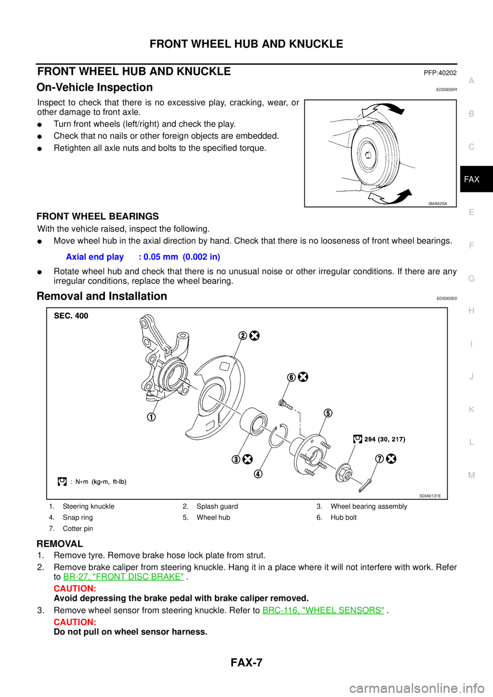
Inspect to check that there is no excessive play, cracking, wear, or
other damage to front axle.
�Turn front wheels (left/right) and check the play.
�Check that no nails or other foreign objects are embedded.
�Retighten all axle nuts and bolts to the specified torque.
FRONT WHEEL BEARINGS
With the vehicle raised, inspect the following.
�Move wheel hub in the axial direction by hand. Check that there is no looseness of front wheel bearings.
�Rotate wheel hub and check that there is no unusual noise or other irregular conditions. If there are any
irregular conditions, replace the wheel bearing.
Removal and InstallationEDS0005S
REMOVAL
1. Remove tyre. Remove brake hose lock plate from strut.
2. Remove brake caliper from steering knuckle. Hang it in a place where it will not interfere with work. Refer
to BR-27, "
FRONT DISC BRAKE" .
CAUTION:
Avoid depressing the brake pedal with brake caliper removed.
3. Remove wheel sensor from steering knuckle. Refer to BRC-116, "
WHEEL SENSORS" .
CAUTION:
Do not pull on wheel sensor harness.
SMA525A
Axial end play : 0.05 mm (0.002 in)
1. Steering knuckle 2. Splash guard 3. Wheel bearing assembly
4. Snap ring 5. Wheel hub 6. Hub bolt
7. Cotter pin
SDIA0131E
Page 2932 of 4555
FAX-8
FRONT WHEEL HUB AND KNUCKLE
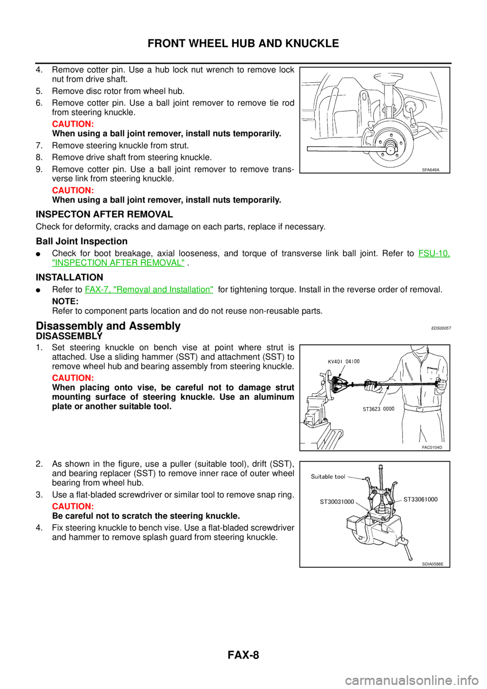
4. Remove cotter pin. Use a hub lock nut wrench to remove lock
nut from drive shaft.
5. Remove disc rotor from wheel hub.
6. Remove cotter pin. Use a ball joint remover to remove tie rod
from steering knuckle.
CAUTION:
When using a ball joint remover, install nuts temporarily.
7. Remove steering knuckle from strut.
8. Remove drive shaft from steering knuckle.
9. Remove cotter pin. Use a ball joint remover to remove trans-
verse link from steering knuckle.
CAUTION:
When using a ball joint remover, install nuts temporarily.
INSPECTON AFTER REMOVAL
Check for deformity, cracks and damage on each parts, replace if necessary.
Ball Joint Inspection
�Check for boot breakage, axial looseness, and torque of transverse link ball joint. Refer to FSU-10,
"INSPECTION AFTER REMOVAL" .
INSTALLATION
�Refer to FAX-7, "Removal and Installation" for tightening torque. Install in the reverse order of removal.
NOTE:
Refer to component parts location and do not reuse non-reusable parts.
Disassembly and AssemblyEDS0005T
DISASSEMBLY
1. Set steering knuckle on bench vise at point where strut is
attached. Use a sliding hammer (SST) and attachment (SST) to
remove wheel hub and bearing assembly from steering knuckle.
CAUTION:
When placing onto vise, be careful not to damage strut
mounting surface of steering knuckle. Use an aluminum
plate or another suitable tool.
2. As shown in the figure, use a puller (suitable tool), drift (SST),
and bearing replacer (SST) to remove inner race of outer wheel
bearing from wheel hub.
3. Use a flat-bladed screwdriver or similar tool to remove snap ring.
CAUTION:
Be careful not to scratch the steering knuckle.
4. Fix steering knuckle to bench vise. Use a flat-bladed screwdriver
and hammer to remove splash guard from steering knuckle.
SFA649A
FAC0104D
SDIA0588E
Page 2933 of 4555
FRONT WHEEL HUB AND KNUCKLE
FAX-9
C
E
F
G
H
I
J
K
L
MA
B
FA X
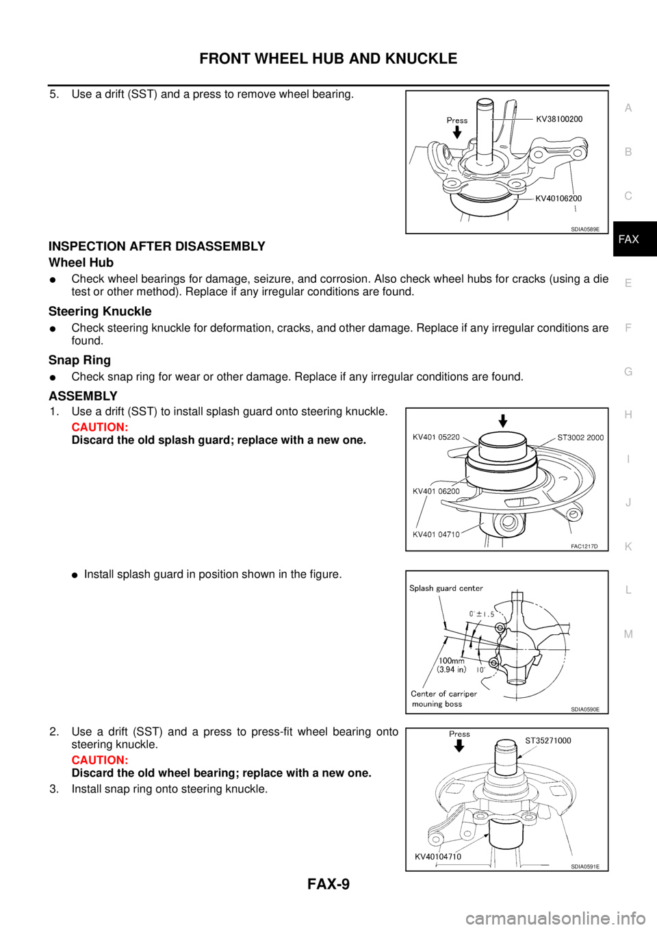
5. Use a drift (SST) and a press to remove wheel bearing.
INSPECTION AFTER DISASSEMBLY
Wheel Hub
�Check wheel bearings for damage, seizure, and corrosion. Also check wheel hubs for cracks (using a die
test or other method). Replace if any irregular conditions are found.
Steering Knuckle
�Check steering knuckle for deformation, cracks, and other damage. Replace if any irregular conditions are
found.
Snap Ring
�Check snap ring for wear or other damage. Replace if any irregular conditions are found.
ASSEMBLY
1. Use a drift (SST) to install splash guard onto steering knuckle.
CAUTION:
Discard the old splash guard; replace with a new one.
�Install splash guard in position shown in the figure.
2. Use a drift (SST) and a press to press-fit wheel bearing onto
steering knuckle.
CAUTION:
Discard the old wheel bearing; replace with a new one.
3. Install snap ring onto steering knuckle.
SDIA0589E
FAC1217D
SDIA0590E
SDIA0591E
Page 2935 of 4555
FRONT DRIVE SHAFT
FAX-11
C
E
F
G
H
I
J
K
L
MA
B
FA X
FRONT DRIVE SHAFTPFP:39100
Removal and InstallationEDS0005U
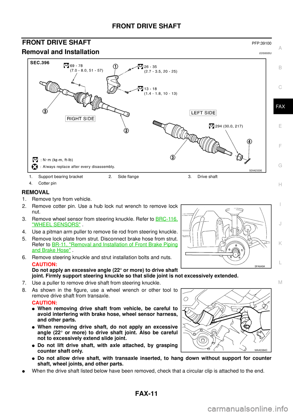
REMOVAL
1. Remove tyre from vehicle.
2. Remove cotter pin. Use a hub lock nut wrench to remove lock
nut.
3. Remove wheel sensor from steering knuckle. Refer to BRC-116,
"WHEEL SENSORS" .
4. Use a pitman arm puller to remove tie rod from steering knuckle.
5. Remove lock plate from strut. Disconnect brake hose from strut.
Refer to BR-11, "
Removal and Installation of Front Brake Piping
and Brake Hose" .
6. Remove steering knuckle and strut installation bolts and nuts.
CAUTION:
Do not apply an excessive angle (22° or more) to drive shaft
joint. Firmly support steering knuckle so that slide joint is not excessively extended.
7. Use a puller to remove drive shaft from steering knuckle.
8. As shown in the figure, use a wheel wrench or other tool to
remove drive shaft from transaxle.
CAUTION:
�When removing drive shaft from vehicle, be careful to
avoid interfering with brake hose, wheel sensor harness,
and other parts.
�When removing drive shaft, do not apply an excessive
angle (22° or more) to drive shaft joint. Also be careful
not to excessively extend slide joint.
�Do not lift drive shaft, with axle attached, by grasping
counter shaft only.
�Do not allow drive shaft, with transaxle inserted, to hang down without support for counter
shaft, wheel joints, and other parts.
�When the drive shaft listed below have been removed, check that a circular clip is attached to the end.
1. Support bearing bracket 2. Side flange 3. Drive shaft
4. Cotter pin
SDIA2333E
SFA649A
MAA0384D