Page 2748 of 4555
AT-484
[ALL]
REPAIR FOR COMPONENT PARTS
6. In order to remove low & reverse brake piston, apply com-
pressed air to oil hole of retainer while holding low & reverse
brake piston.
CAUTION:
Apply air gradually and allow low & reverse brake piston to
come out evenly.
7. Remove D-rings from low & reverse brake piston.
INSPECTION
Low and Reverse Brake Snap Ring, Spring Retainer and Return Springs
�Check for deformation, fatigue or damage.
If necessary, replace.
�When replacing spring retainer and return springs, replace them as a set.
Low and Reverse Brake Drive Plate
�Check the facing for burns, cracks or damage.
�Measure the thickness of facing.
�If not within wear limit, replace.
ASSEMBLY
1. Install D-rings on piston.
CAUTION:
�Apply ATF to both parts.
�Do not reuse D-ring.
SCIA3651E
SCIA4381E
Thickness of drive plate:
Standard value 1.8 mm (0.071 in)
Wear limit 1.6 mm (0.063 in)
SAT162D
SCIA2998E
Page 2750 of 4555
AT-486
[ALL]
REPAIR FOR COMPONENT PARTS
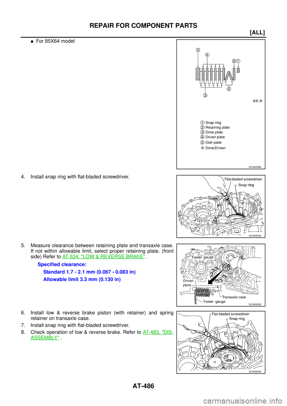
�For 85X64 model
4. Install snap ring with flat-bladed screwdriver.
5. Measure clearance between retaining plate and transaxle case.
If not within allowable limit, select proper retaining plate. (front
side) Refer to AT- 5 3 4 , "
LOW & REVERSE BRAKE" .
6. Install low & reverse brake piston (with retainer) and spring
retainer on transaxle case.
7. Install snap ring with flat-bladed screwdriver.
8. Check operation of low & reverse brake. Refer to AT- 4 8 3 , "
DIS-
ASSEMBLY" .
SCIA4066E
SCIA4904E
Specified clearance:
Standard 1.7 - 2.1 mm (0.067 - 0.083 in)
Allowable limit 3.3 mm (0.130 in)
SCIA3654E
SCIA4903E
Page 2753 of 4555
REPAIR FOR COMPONENT PARTS
AT-489
[ALL]
D
E
F
G
H
I
J
K
L
MA
B
AT
INSPECTION
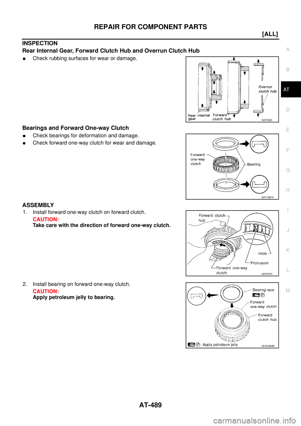
Rear Internal Gear, Forward Clutch Hub and Overrun Clutch Hub
�Check rubbing surfaces for wear or damage.
Bearings and Forward One-way Clutch
�Check bearings for deformation and damage.
�Check forward one-way clutch for wear and damage.
ASSEMBLY
1. Install forward one-way clutch on forward clutch.
CAUTION:
Take care with the direction of forward one-way clutch.
2. Install bearing on forward one-way clutch.
CAUTION:
Apply petroleum jelly to bearing.
SAT256D
SAT158FA
SAT976H
SCIA3658E
Page 2754 of 4555
AT-490
[ALL]
REPAIR FOR COMPONENT PARTS
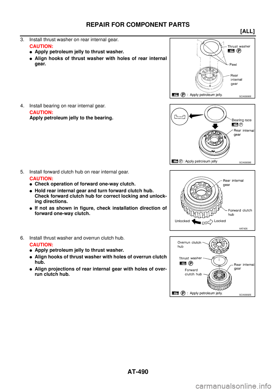
3. Install thrust washer on rear internal gear.
CAUTION:
�Apply petroleum jelly to thrust washer.
�Align hooks of thrust washer with holes of rear internal
gear.
4. Install bearing on rear internal gear.
CAUTION:
Apply petroleum jelly to the bearing.
5. Install forward clutch hub on rear internal gear.
CAUTION:
�Check operation of forward one-way clutch.
�Hold rear internal gear and turn forward clutch hub.
Check forward clutch hub for correct locking and unlock-
ing directions.
�If not as shown in figure, check installation direction of
forward one-way clutch.
6. Install thrust washer and overrun clutch hub.
CAUTION:
�Apply petroleum jelly to thrust washer.
�Align hooks of thrust washer with holes of overrun clutch
hub.
�Align projections of rear internal gear with holes of over-
run clutch hub.
SCIA3690E
SCIA3659E
AAT426
SCIA3692E
Page 2757 of 4555
![NISSAN X-TRAIL 2005 Service Repair Manual REPAIR FOR COMPONENT PARTS
AT-493
[ALL]
D
E
F
G
H
I
J
K
L
MA
B
AT
7. Press out reduction pinion gear bearing inner race from reduc-
tion pinion gear.
8. Remove reduction pinion gear bearing outer ra](/manual-img/5/57403/w960_57403-2756.png "NISSAN X-TRAIL 2005 Service Repair Manual REPAIR FOR COMPONENT PARTS
AT-493
[ALL]
D
E
F
G
H
I
J
K
L
MA
B
AT
7. Press out reduction pinion gear bearing inner race from reduc-
tion pinion gear.
8. Remove reduction pinion gear bearing outer ra")
REPAIR FOR COMPONENT PARTS
AT-493
[ALL]
D
E
F
G
H
I
J
K
L
MA
B
AT
7. Press out reduction pinion gear bearing inner race from reduc-
tion pinion gear.
8. Remove reduction pinion gear bearing outer race from transaxle
case.
INSPECTION
Output Shaft, Idler Gear and Reduction Pinion Gear
�Check shafts for cracks, wear or bending.
�Check gears for wear, chips and cracks.
Bearing
�Make sure bearings roll freely and are free from noise, cracks,
pitting or wear.
�When replacing taper roller bearing, replace outer and inner
race as a set.
Seal Ring Clearance
�Install new seal rings to output shaft.
�Measure the clearance between seal ring and ring groove of
output shaft.
�If not within allowable limit, replace output shaft.
�Install new seal rings to bearing retainer.
�Measure the clearance between seal ring and ring groove of bearing retainer.
SAT169F
SAT319K
SPD715
Standard clearance:
0.10 - 0.25 mm (0.0039 - 0.0098 in)
Allowable limit:
0.25 mm (0.0098 in)
Standard clearance:
0.10 - 0.30 mm (0.0039 - 0.0118 in)
SAT171F
Page 2758 of 4555
AT-494
[ALL]
REPAIR FOR COMPONENT PARTS
�If not within allowable limit, replace bearing retainer.
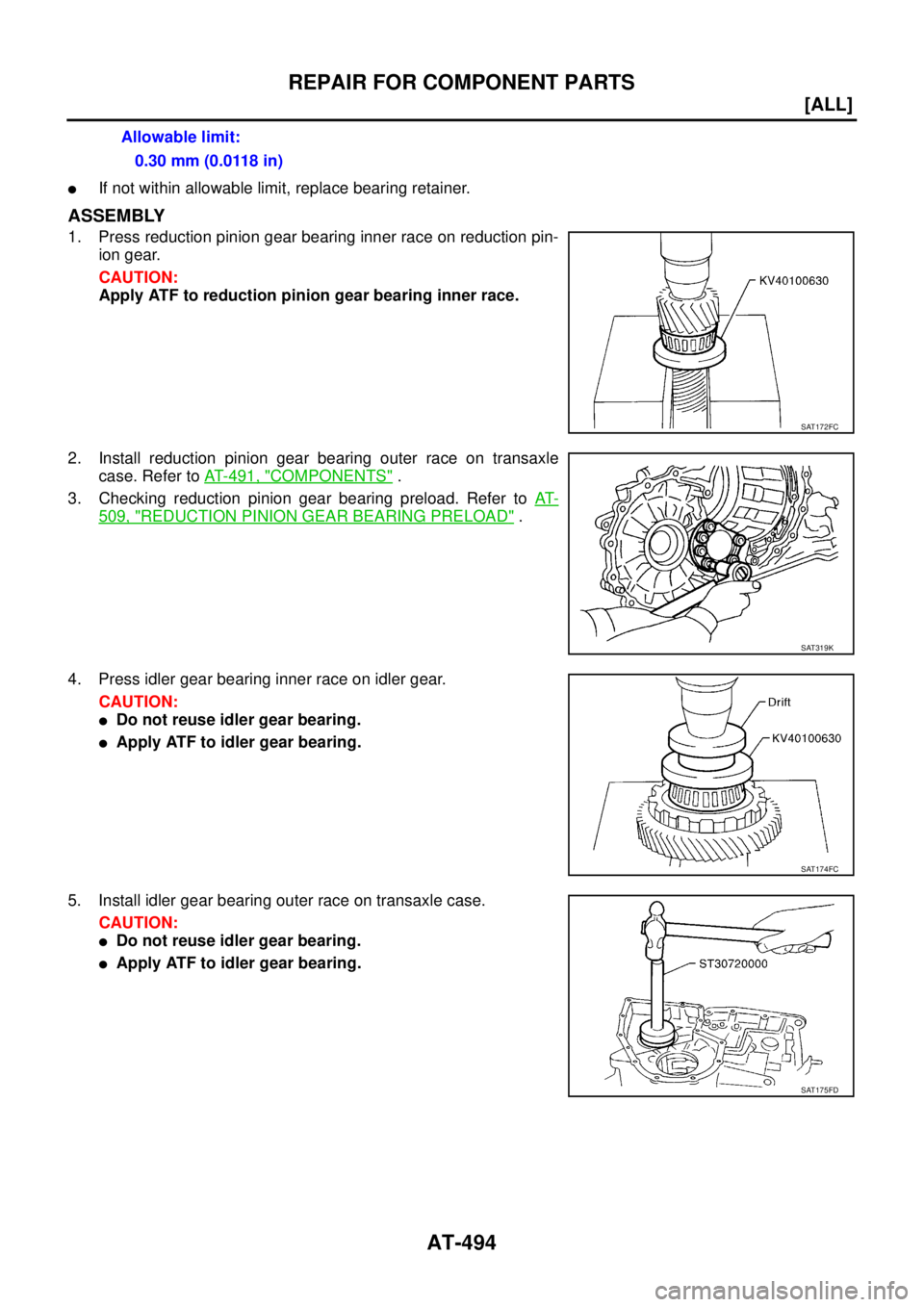
ASSEMBLY
1. Press reduction pinion gear bearing inner race on reduction pin-
ion gear.
CAUTION:
Apply ATF to reduction pinion gear bearing inner race.
2. Install reduction pinion gear bearing outer race on transaxle
case. Refer to AT- 4 9 1 , "
COMPONENTS" .
3. Checking reduction pinion gear bearing preload. Refer to AT-
509, "REDUCTION PINION GEAR BEARING PRELOAD" .
4. Press idler gear bearing inner race on idler gear.
CAUTION:
�Do not reuse idler gear bearing.
�Apply ATF to idler gear bearing.
5. Install idler gear bearing outer race on transaxle case.
CAUTION:
�Do not reuse idler gear bearing.
�Apply ATF to idler gear bearing.Allowable limit:
0.30 mm (0.0118 in)
SAT172FC
SAT319K
SAT174FC
SAT175FD
Page 2763 of 4555
REPAIR FOR COMPONENT PARTS
AT-499
[ALL]
D
E
F
G
H
I
J
K
L
MA
B
AT
9. Remove spring retainer, O/D servo return spring, band servo
thrust washer and band servo piston stem from band servo pis-
ton.
10. Remove O-rings from servo piston retainer.
11. Remove D-rings from band servo piston.
INSPECTION
Pistons, Retainers and Piston Stem
�Check frictional surfaces for abnormal wear or damage.
Return Springs
�Check for deformation or damage.
�Measure the free length and outer diameter. Refer to AT- 5 3 8 ,
"Band Servo" .
SCIA4746E
SCIA3671E
SCIA3688E
AAT884
Page 2768 of 4555
AT-504
[ALL]
REPAIR FOR COMPONENT PARTS
3. Remove differential side bearing outer race, and side bearing
adjusting shim from transaxle case.
4. Drive out lock pin.
5. Draw out pinion mate shaft.
6. Remove pinion mate gears, pinion mate gear thrust washers,
side gears and side gear thrust washers.
INSPECTION
Gear, Washer, Shaft and Case
�Check mating surfaces of differential case, side gears, pinion
mate gears and pinion mate shaft.
�Check washers for wear.
SAT010FA
SAT904DA
SAT316D
SAT544F
![NISSAN X-TRAIL 2005 Service Repair Manual AT-484
[ALL]
REPAIR FOR COMPONENT PARTS
6. In order to remove low & reverse brake piston, apply com-
pressed air to oil hole of retainer while holding low & reverse
brake piston.
CAUTION:
Apply air](/manual-img/5/57403/w960_57403-2747.png "NISSAN X-TRAIL 2005 Service Repair Manual AT-484
[ALL]
REPAIR FOR COMPONENT PARTS
6. In order to remove low & reverse brake piston, apply com-
pressed air to oil hole of retainer while holding low & reverse
brake piston.
CAUTION:
Apply air")
![NISSAN X-TRAIL 2005 Service Repair Manual REPAIR FOR COMPONENT PARTS
AT-499
[ALL]
D
E
F
G
H
I
J
K
L
MA
B
AT
9. Remove spring retainer, O/D servo return spring, band servo
thrust washer and band servo piston stem from band servo pis-
ton.
10](/manual-img/5/57403/w960_57403-2762.png "NISSAN X-TRAIL 2005 Service Repair Manual REPAIR FOR COMPONENT PARTS
AT-499
[ALL]
D
E
F
G
H
I
J
K
L
MA
B
AT
9. Remove spring retainer, O/D servo return spring, band servo
thrust washer and band servo piston stem from band servo pis-
ton.
10")
![NISSAN X-TRAIL 2005 Service Repair Manual AT-504
[ALL]
REPAIR FOR COMPONENT PARTS
3. Remove differential side bearing outer race, and side bearing
adjusting shim from transaxle case.
4. Drive out lock pin.
5. Draw out pinion mate shaft.
6.](/manual-img/5/57403/w960_57403-2767.png "NISSAN X-TRAIL 2005 Service Repair Manual AT-504
[ALL]
REPAIR FOR COMPONENT PARTS
3. Remove differential side bearing outer race, and side bearing
adjusting shim from transaxle case.
4. Drive out lock pin.
5. Draw out pinion mate shaft.
6.")