Page 2695 of 4555
DISASSEMBLY
AT-431
[ALL]
D
E
F
G
H
I
J
K
L
MA
B
AT
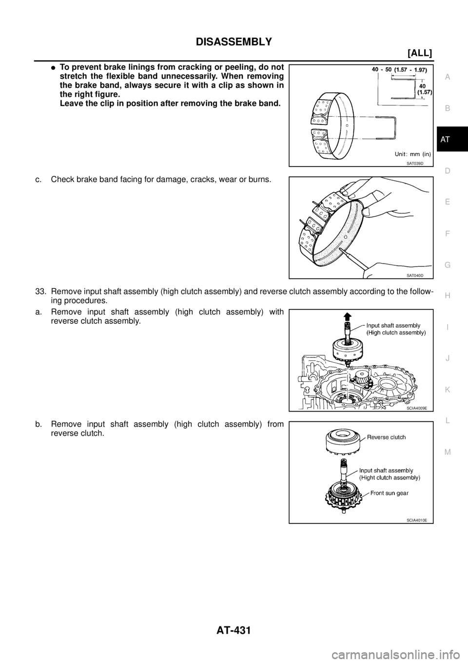
�To prevent brake linings from cracking or peeling, do not
stretch the flexible band unnecessarily. When removing
the brake band, always secure it with a clip as shown in
the right figure.
Leave the clip in position after removing the brake band.
c. Check brake band facing for damage, cracks, wear or burns.
33. Remove input shaft assembly (high clutch assembly) and reverse clutch assembly according to the follow-
ing procedures.
a. Remove input shaft assembly (high clutch assembly) with
reverse clutch assembly.
b. Remove input shaft assembly (high clutch assembly) from
reverse clutch.
SAT039D
SAT040D
SCIA4009E
SCIA4010E
Page 2696 of 4555
AT-432
[ALL]
DISASSEMBLY
c. Remove needle bearing from input shaft assembly (high clutch
drum) and check for damage or wear.
d. Remove high clutch hub (with front sun gear) and needle bear-
ing from input shaft assembly (high clutch drum) and check for
damage or wear.
e. Remove front sun gear and needle bearing from high clutch hab
and check for damage or wear.
f. Remove bearing race from front sun gear and check for damage
or wear.
34. Remove needle bearing from transaxle case and check for dam-
age or wear.
35. Apply compressed air and check to see that low and reverse
brake operates.
SCIA4872E
SCIA5195E
SCIA4013E
SCIA4014E
SAT138F
Page 2697 of 4555
DISASSEMBLY
AT-433
[ALL]
D
E
F
G
H
I
J
K
L
MA
B
AT
36. Remove low one-way clutch and front planetary carrier assembly according to the following procedures.
a. Remove snap ring with flat-bladed screwdriver.
b. Remove low one-way clutch with a hook made of wire.
c. Check low one-way clutch for damage or wear.
d. Remove snap ring with flat-bladed screwdriver.
SCIA4743E
AAT889
SCIA4744E
Page 2698 of 4555
AT-434
[ALL]
DISASSEMBLY
e. Remove front planetary carrier with low & reverse brake piston
and retainer.
f. Remove low and reverse brake spring retainer.
CAUTION:
Do not remove return springs from spring retainer.
g. Check that low one-way clutch rotates in the direction of the
clockwise arrow and locks in the opposite direction.
h. Remove needle bearing, low and reverse brake piston and
retainer from front planetary carrier.
i. Check front planetary carrier, low & reverse brake piston,
retainer and needle bearing for damage or wear.
j. Check front planetary carrier, low one-way clutch and needle
bearing for damage or wear.
k. Check clearance between planetary gears and planetary carrier
with feeler gauge.
Replace front planetary carrier if the clearance exceeds
allowable limit.
SAT023F
SAT148F
SAT048D
SCIA3636E
Standard clearance: 0.20 - 0.70 mm (0.0079 - 0.0276 in)
Allowable limit: 0.80 mm (0.0315 in)
SAT025F
Page 2699 of 4555
DISASSEMBLY
AT-435
[ALL]
D
E
F
G
H
I
J
K
L
MA
B
AT
37. Remove rear planetary carrier and rear sun gear according to
the following procedures.
a. Remove rear planetary carrier (with rear sun gear) from tran-
saxle case.
b. Remove rear sun gear from rear planetary carrier.
c. Remove needle bearings from rear planetary carrier.
d. Check rear planetary carrier, rear sun gear and needle bearings
for damage or wear.
e. Check clearance between pinion washer and rear planetary car-
rier with feeler gauge.
Replace rear planetary carrier if the clearance exceeds allow-
able limit.
38. Remove rear internal gear and forward clutch hub from tran-
saxle case.
SAT026F
SAT027F
SCIA4016E
Standard clearance: 0.20 - 0.70 mm (0.0079 - 0.0276 in)
Allowable limit: 0.80 mm (0.0315 in)
SAT054D
SAT029F
Page 2700 of 4555
AT-436
[ALL]
DISASSEMBLY
39. Remove overrun clutch hub from transaxle case.
40. Remove needle bearing from overrun clutch hub and check for
damage or wear.
41. Remove forward clutch assembly and overrun clutch assembly
from transaxle case.
42. Remove needle bearing from transaxle case and check for dam-
age or wear.
43. Remove output shaft assembly according to the following proce-
dures.
a. Remove side cover bolts.
CAUTION:
�Do not mix bolts A and B.
�Always replace bolts A as they are self-sealing bolts.
SAT030F
SCIA4017E
SCIA4878E
SCIA4019E
AAT850
Page 2703 of 4555
DISASSEMBLY
AT-439
[ALL]
D
E
F
G
H
I
J
K
L
MA
B
AT
45. Remove return spring and parking pawl spacer with flat-bladed
screwdriver from parking shaft.
46. Draw out parking shaft and remove parking pawl from transaxle
case.
47. Check parking pawl and shaft for damage or wear.
48. Remove parking actuator support from transaxle case.
49. Check parking actuator support for damage or wear.
50. Remove LH differential side oil seal with flat-bladed screwdriver
from transaxle case.
CAUTION:
Be careful not to scratch transaxle case.
SCIA4881E
SAT066D
SAT040F
Page 2705 of 4555
REPAIR FOR COMPONENT PARTS
AT-441
[ALL]
D
E
F
G
H
I
J
K
L
MA
B
AT
3. Drive and pull out parking rod plate retaining pin.
4. Remove parking rod plate (with parking rod) from manual shaft.
5. Draw out parking rod (with parking rod plate) from transaxle
case.
6. Remove parking rod from parking rod plate.
7. Pull out manual shaft retaining pin.
8. Remove manual shaft and manual plate from transaxle case.
9. Remove manual shaft oil seal.
CAUTION:
Be careful not to scratch transaxle case.
INSPECTION
�Check component parts for wear or damage. Replace if necessary.
INSTALLATION
1. Use a drift [commercial service tool φ 22 mm (0.87 in)] to drive
manual shaft oil seal into the transaxle case.
CAUTION:
�Do not reuse manual shaft oil seal.
�Apply ATF to outer surface of manual shaft oil seal.
2. Install parking rod to parking rod plate.
SAT043FC
SAT049F
SAT080D
SAT081D
![NISSAN X-TRAIL 2005 Service Repair Manual AT-432
[ALL]
DISASSEMBLY
c. Remove needle bearing from input shaft assembly (high clutch
drum) and check for damage or wear.
d. Remove high clutch hub (with front sun gear) and needle bear-
ing from](/manual-img/5/57403/w960_57403-2695.png "NISSAN X-TRAIL 2005 Service Repair Manual AT-432
[ALL]
DISASSEMBLY
c. Remove needle bearing from input shaft assembly (high clutch
drum) and check for damage or wear.
d. Remove high clutch hub (with front sun gear) and needle bear-
ing from")
![NISSAN X-TRAIL 2005 Service Repair Manual DISASSEMBLY
AT-433
[ALL]
D
E
F
G
H
I
J
K
L
MA
B
AT
36. Remove low one-way clutch and front planetary carrier assembly according to the following procedures.
a. Remove snap ring with flat-bladed scre](/manual-img/5/57403/w960_57403-2696.png "NISSAN X-TRAIL 2005 Service Repair Manual DISASSEMBLY
AT-433
[ALL]
D
E
F
G
H
I
J
K
L
MA
B
AT
36. Remove low one-way clutch and front planetary carrier assembly according to the following procedures.
a. Remove snap ring with flat-bladed scre")
![NISSAN X-TRAIL 2005 Service Repair Manual AT-434
[ALL]
DISASSEMBLY
e. Remove front planetary carrier with low & reverse brake piston
and retainer.
f. Remove low and reverse brake spring retainer.
CAUTION:
Do not remove return springs from s](/manual-img/5/57403/w960_57403-2697.png "NISSAN X-TRAIL 2005 Service Repair Manual AT-434
[ALL]
DISASSEMBLY
e. Remove front planetary carrier with low & reverse brake piston
and retainer.
f. Remove low and reverse brake spring retainer.
CAUTION:
Do not remove return springs from s")
![NISSAN X-TRAIL 2005 Service Repair Manual DISASSEMBLY
AT-435
[ALL]
D
E
F
G
H
I
J
K
L
MA
B
AT
37. Remove rear planetary carrier and rear sun gear according to
the following procedures.
a. Remove rear planetary carrier (with rear sun gear) fr](/manual-img/5/57403/w960_57403-2698.png "NISSAN X-TRAIL 2005 Service Repair Manual DISASSEMBLY
AT-435
[ALL]
D
E
F
G
H
I
J
K
L
MA
B
AT
37. Remove rear planetary carrier and rear sun gear according to
the following procedures.
a. Remove rear planetary carrier (with rear sun gear) fr")
![NISSAN X-TRAIL 2005 Service Repair Manual AT-436
[ALL]
DISASSEMBLY
39. Remove overrun clutch hub from transaxle case.
40. Remove needle bearing from overrun clutch hub and check for
damage or wear.
41. Remove forward clutch assembly and ove](/manual-img/5/57403/w960_57403-2699.png "NISSAN X-TRAIL 2005 Service Repair Manual AT-436
[ALL]
DISASSEMBLY
39. Remove overrun clutch hub from transaxle case.
40. Remove needle bearing from overrun clutch hub and check for
damage or wear.
41. Remove forward clutch assembly and ove")
![NISSAN X-TRAIL 2005 Service Repair Manual DISASSEMBLY
AT-439
[ALL]
D
E
F
G
H
I
J
K
L
MA
B
AT
45. Remove return spring and parking pawl spacer with flat-bladed
screwdriver from parking shaft.
46. Draw out parking shaft and remove parking paw](/manual-img/5/57403/w960_57403-2702.png "NISSAN X-TRAIL 2005 Service Repair Manual DISASSEMBLY
AT-439
[ALL]
D
E
F
G
H
I
J
K
L
MA
B
AT
45. Remove return spring and parking pawl spacer with flat-bladed
screwdriver from parking shaft.
46. Draw out parking shaft and remove parking paw")
![NISSAN X-TRAIL 2005 Service Repair Manual REPAIR FOR COMPONENT PARTS
AT-441
[ALL]
D
E
F
G
H
I
J
K
L
MA
B
AT
3. Drive and pull out parking rod plate retaining pin.
4. Remove parking rod plate (with parking rod) from manual shaft.
5. Draw out](/manual-img/5/57403/w960_57403-2704.png "NISSAN X-TRAIL 2005 Service Repair Manual REPAIR FOR COMPONENT PARTS
AT-441
[ALL]
D
E
F
G
H
I
J
K
L
MA
B
AT
3. Drive and pull out parking rod plate retaining pin.
4. Remove parking rod plate (with parking rod) from manual shaft.
5. Draw out")