Page 2652 of 4555
AT-388
[ALL]
LINE PRESSURE SOLENOID VALVE
2. Depress accelerator pedal completely and wait at least 5 sec-
onds.
3. If check result is NG, go to AT- 3 9 0 , "
Diagnostic Procedure" .
WITHOUT CONSULT-II
1. Start engine.
2. With brake pedal depressed, shift the lever from P → N → D → N → P positions.
3. Perform self-diagnosis.
Refer to AT- 5 2 , "
Diagnostic Procedure Without CONSULT-II" .
4. If the check result is NG, go to AT- 3 9 0 , "
Diagnostic Procedure" .
SCIA5358E
SCIA5600E
Page 2654 of 4555
![NISSAN X-TRAIL 2005 Service Repair Manual AT-390
[ALL]
LINE PRESSURE SOLENOID VALVE
TERMINALS AND REFERENCE VALUE MEASURED BETWEEN EACH TERMINAL
Diagnostic ProcedureECS004UH
1. CHECK INPUT SIGNAL
With CONSULT-II
1. Turn ignition switch ON](/manual-img/5/57403/w960_57403-2653.png "NISSAN X-TRAIL 2005 Service Repair Manual AT-390
[ALL]
LINE PRESSURE SOLENOID VALVE
TERMINALS AND REFERENCE VALUE MEASURED BETWEEN EACH TERMINAL
Diagnostic ProcedureECS004UH
1. CHECK INPUT SIGNAL
With CONSULT-II
1. Turn ignition switch ON")
AT-390
[ALL]
LINE PRESSURE SOLENOID VALVE
TERMINALS AND REFERENCE VALUE MEASURED BETWEEN EACH TERMINAL
Diagnostic ProcedureECS004UH
1. CHECK INPUT SIGNAL
With CONSULT-II
1. Turn ignition switch ON. (Do not start engine.)
2. Select “MAIN SIGNALS” in “DATA MONITOR” mode for “A/T” with CONSULT-II.
3. Read out the value of “LINE PRES DTY” while driving.
Check the value changes according to driving speed.
Without CONSULT-II
1. Turn ignition switch ON. (Do not start engine.)
2. Check voltage between TCM connector and ground.
OK or NG
OK >> GO TO 5.
NG >> GO TO 2.
Te r m i -
nal No.Wire color Item ConditionJudgement stan-
dard
(Approx.)
1R/WLine pressure
solenoid valveWhen releasing accelerator pedal
after warming up engine.1.5 - 3.0V
When depressing accelerator pedal
fully after warming up engine.0V
2P/BLine pressure
solenoid valve
(with dropping
resistor)When releasing accelerator pedal
after warming up engine.5 - 14V
When depressing accelerator pedal
fully after warming up engine.0V
Monitor item Condition Display value
LINE PRES
DTY (%)Line pressure low – Line pressure high 24% – 95%
SCIA3251E
Name Connec-
tor No. Terminal
No. (Wire
color) ConditionJudge-
ment stan-
dard
(Approx.)
Line pres-
sure sole-
noid valve F46 1 (R/W) -
GroundWhen releasing acceler-
ator pedal after warming
up engine.1.5 - 3.0V
When depressing accel-
erator pedal fully after
warming up engine.0V
Line pres-
sure sole-
noid valve
(with drop-
ping resis-
tor) F46 2 (P/B) -
GroundWhen releasing acceler-
ator pedal after warming
up engine.5 - 14V
When depressing accel-
erator pedal fully after
warming up engine.0V
SCIA3267E
Page 2655 of 4555
LINE PRESSURE SOLENOID VALVE
AT-391
[ALL]
D
E
F
G
H
I
J
K
L
MA
B
AT
2. CHECK DROPPING RESISTOR
1. Turn ignition switch OFF.
2. Disconnect dropping resistor harness connector in engine room.
3. Check resistance between terminal 1 and 2.
OK or NG
OK >> GO TO 3.
NG >> Repair or replace damaged parts.
3. CHECK VALVE RESISTANCE
1. Turn ignition switch OFF.
2. Disconnect terminal cord assembly connector in engine room.
3. Check resistance between terminal cord assembly harness con-
nector F23 terminal 4 (R/W) and ground.
OK or NG
OK >> GO TO 4.
NG >> Repair or replace damaged parts.Resistance: Approx.12Ω
SCIA3276E
Resistance: 2.5 - 5Ω
SCIA3457E
Page 2656 of 4555
![NISSAN X-TRAIL 2005 Service Repair Manual AT-392
[ALL]
LINE PRESSURE SOLENOID VALVE
4. CHECK HARNESS BETWEEN TCM AND TERMINAL CORD ASSEMBLY HARNESS CONNECTOR
1. Turn ignition switch OFF.
2. Disconnect terminal cord assembly harness connect](/manual-img/5/57403/w960_57403-2655.png "NISSAN X-TRAIL 2005 Service Repair Manual AT-392
[ALL]
LINE PRESSURE SOLENOID VALVE
4. CHECK HARNESS BETWEEN TCM AND TERMINAL CORD ASSEMBLY HARNESS CONNECTOR
1. Turn ignition switch OFF.
2. Disconnect terminal cord assembly harness connect")
AT-392
[ALL]
LINE PRESSURE SOLENOID VALVE
4. CHECK HARNESS BETWEEN TCM AND TERMINAL CORD ASSEMBLY HARNESS CONNECTOR
1. Turn ignition switch OFF.
2. Disconnect terminal cord assembly harness connector and TCM connector.
3. Check continuity between terminal cord assembly harness con-
nector and TCM connector.
4. Check continuity between terminal cord assembly harness con-
nector and dropping resistor harness connector.
5. Check continuity between dropping resistor harness connector
and TCM connector.
6. If OK, check harness for short to ground and short to power.
7. If OK, check continuity between ground and transaxle assembly.
8. Reinstall any part removed.
OK or NG
OK >> GO TO 5.
NG >> Repair open circuit or short to ground or short to power in harness or connectors.
5. CHECK DTC
Perform AT- 3 8 7 , "
DTC Confirmation Procedure" .
OK or NG
OK >>INSPECTION END
NG >> GO TO 6.
6. CHECK TCM
1. Check TCM input/output signal. Refer to AT- 9 4 , "
TCM Terminals and Reference Value" .
2. If NG, recheck TCM pin terminals for damage or loose connection with harness connector.
OK or NG
OK >>INSPECTION END
NG >> Repair or replace damaged parts.
Item Connector No.Terminal No.
(Wire color)Continuity
TCM F46 1 (R/W)
Ye s
Terminal cord assembly
harness connectorF23 4 (R/W)
SCIA3272E
Item Connector No.Terminal No.
(Wire color)Continuity
Dropping resistor harness
connectorE49 1 (R/W)
Ye s
Terminal cord assembly
harness connectorF23 4 (R/W)
SCIA3273E
Item Connector No.Terminal No.
(Wire color)Continuity
TCM F46 2 (P/B)
Ye s
Dropping resistor harness
connectorE49 2 (P/B)
SCIA3274E
Page 2657 of 4555
LINE PRESSURE SOLENOID VALVE
AT-393
[ALL]
D
E
F
G
H
I
J
K
L
MA
B
AT
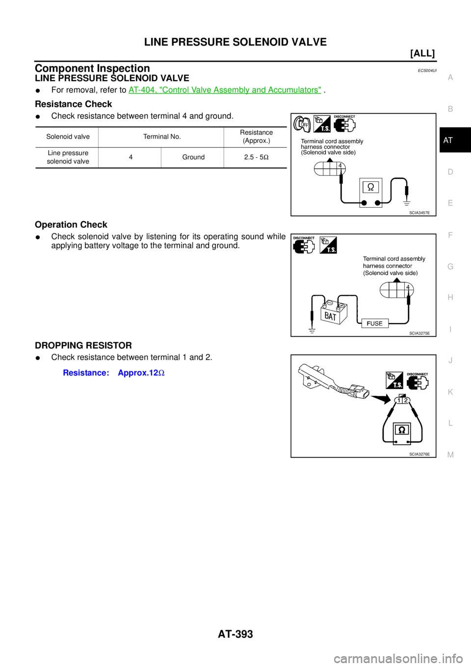
Component InspectionECS004UI
LINE PRESSURE SOLENOID VALVE
�For removal, refer to AT- 4 0 4 , "Control Valve Assembly and Accumulators" .
Resistance Check
�Check resistance between terminal 4 and ground.
Operation Check
�Check solenoid valve by listening for its operating sound while
applying battery voltage to the terminal and ground.
DROPPING RESISTOR
�Check resistance between terminal 1 and 2.
Solenoid valve Terminal No.Resistance
(Approx.)
Line pressure
solenoid valve4Ground2.5 - 5Ω
SCIA3457E
SCIA3275E
Resistance: Approx.12Ω
SCIA3276E
Page 2660 of 4555
![NISSAN X-TRAIL 2005 Service Repair Manual AT-396
[ALL]
MAIN POWER SUPPLY AND GROUND CIRCUIT
TERMINALS AND REFERENCE VALUE MEASURED BETWEEN EACH TERMINAL
Diagnostic ProcedureECS004TI
1. CHECK TCM POWER SOURCE
1. Turn ignition switch to ON.](/manual-img/5/57403/w960_57403-2659.png "NISSAN X-TRAIL 2005 Service Repair Manual AT-396
[ALL]
MAIN POWER SUPPLY AND GROUND CIRCUIT
TERMINALS AND REFERENCE VALUE MEASURED BETWEEN EACH TERMINAL
Diagnostic ProcedureECS004TI
1. CHECK TCM POWER SOURCE
1. Turn ignition switch to ON.")
AT-396
[ALL]
MAIN POWER SUPPLY AND GROUND CIRCUIT
TERMINALS AND REFERENCE VALUE MEASURED BETWEEN EACH TERMINAL
Diagnostic ProcedureECS004TI
1. CHECK TCM POWER SOURCE
1. Turn ignition switch to ON. (Do not start engine.)
2. Check voltage between TCM terminals 10, 19, 28 and ground.
3. Turn ignition switch to OFF.
4. Check voltage between TCM terminal 10, 19, 28 and ground.
OK or NG
OK >> GO TO 3.
NG >> GO TO 2.
2. DETECT MALFUNCTIONING ITEM
Check the following items:
�Harness for short or open between ignition switch and TCM terminals 10, 19 and 28
�Fuse
�Ignition switch
Refer to “PG-2, "
POWER SUPPLY ROUTING" , “POWER SUPPLY ROUTING”.
OK or NG
OK >> GO TO 4
NG >> Repair or replace damaged parts.
Te r m i -
nal No.Wire color Item ConditionJudgement stan-
dard
(Approx.)
10 BR/W Power source
or When turning ignition switch to “ON”. Battery voltage
When turning ignition switch to
“OFF”.0V
19 BR/W Power source Same as No. 10
25 B/W Ground Always 0V
28 LPower source
(Memory back-up)Always Battery voltage
48 B/W Ground Always 0V
Name Connec-
tor No. Terminal
No. (Wire
color)Judgement standard (Approx.)
Power source F4610 (BR/W) Battery voltage
19 (BR/W) Battery voltage
Power source
(Memory back-up)F47 28 (L) Battery voltage
SCIA0713E
Name Connec-
tor No. Terminal No.
(Wire color)Judgement standard
(Approx.)
Power source F4610 (BR/W) 0V
19 (BR/W) 0V
Power source
(Memory back-up)F47 28 (L) Battery voltage
SCIA2657E
Page 2661 of 4555
MAIN POWER SUPPLY AND GROUND CIRCUIT
AT-397
[ALL]
D
E
F
G
H
I
J
K
L
MA
B
AT
3. CHECK TCM GROUND CIRCUIT
1. Turn ignition switch to OFF.
2. Disconnect TCM harness connector.
3. Check continuity between TCM terminals 25, 48 and ground.
OK or NG
OK >> GO TO 4.
NG >> Repair open circuit or short to ground or short to power
in harness or connectors.
4. CHECK DTC
Perform AT- 3 9 4 , "
DTC Confirmation Procedure" .
OK or NG
OK >>INSPECTION END
NG >> GO TO 5.
5. CHECK TCM
1. Check TCM input/output signal. Refer to AT- 9 4 , "
TCM Terminals and Reference Value" .
2. If NG, recheck TCM pin terminals for damage or loose connection with harness connector.
OK or NG
OK >>INSPECTION END
NG >> Repair or replace damaged parts.
Name Connec-
tor No. Terminal No.
(Wire color)Continuity
Ground F4725 (B), 48 (B)
-GroundYe s
SCIA2671E
Page 2664 of 4555
![NISSAN X-TRAIL 2005 Service Repair Manual AT-400
[ALL]
A/T SHIFT LOCK SYSTEM
Diagnostic ProcedureECS00408
SYMPTOM 1:
�Selector lever cannot be moved from “P” position with key in ON position and brake pedal
applied.
�Selector lever can](/manual-img/5/57403/w960_57403-2663.png "NISSAN X-TRAIL 2005 Service Repair Manual AT-400
[ALL]
A/T SHIFT LOCK SYSTEM
Diagnostic ProcedureECS00408
SYMPTOM 1:
�Selector lever cannot be moved from “P” position with key in ON position and brake pedal
applied.
�Selector lever can")
AT-400
[ALL]
A/T SHIFT LOCK SYSTEM
Diagnostic ProcedureECS00408
SYMPTOM 1:
�Selector lever cannot be moved from “P” position with key in ON position and brake pedal
applied.
�Selector lever can be moved from “P” position with key in ON position and brake pedal released.
�Selector lever can be moved from “P” position when key is removed from key cylinder.
SYMPTOM 2:
�Ignition key cannot be removed when selector lever is set to “P” position.
�Ignition key can be removed when selector lever is set to any position except “P”.
1. CHECK KEY INTERLOCK CABLE
Check key interlock cable for damage.
OK or NG
OK >> GO TO 2.
NG >> Repair key interlock cable. Refer to AT- 4 0 2 , "
KEY INTERLOCK CABLE" .
2. CHECK SELECTOR LEVER POSITION
Check selector lever position for damage.
OK or NG
OK >> GO TO 3.
NG >> Check selector lever. Refer to AT- 4 0 9 , "
PARK/NEUTRAL POSITION (PNP) SWITCH ADJUST-
MENT" .
3. CHECK SHIFT LOCK SOLENOID AND PARK POSITION SWITCH
1. Turn ignition switch to ON. (Do not start engine.)
2. Selector lever is set in P position.
3. Check operation sound.
OK or NG
OK >>INSPECTION END
NG >> GO TO 4.
4. CHECK POWER SOURCE
1. Turn ignition switch to ON. (Do not start engine.)
2. Check voltage between A/T device harness connector M58 ter-
minal 5 (P) and ground.
OK or NG
OK >> GO TO 7.
NG >> GO TO 5.
Condition Brake pedal Operation sound
When ignition switch is turned to
“ON” position and selector lever
is set in “P” position.Depressed Yes
Released No
Voltage:
Brake pedal depressed:
Battery voltage
Brake pedal released:
0V
SCIA5337E
![NISSAN X-TRAIL 2005 Service Repair Manual AT-388
[ALL]
LINE PRESSURE SOLENOID VALVE
2. Depress accelerator pedal completely and wait at least 5 sec-
onds.
3. If check result is NG, go to AT- 3 9 0 , "
Diagnostic Procedure" .
WITHOUT CONSU](/manual-img/5/57403/w960_57403-2651.png "NISSAN X-TRAIL 2005 Service Repair Manual AT-388
[ALL]
LINE PRESSURE SOLENOID VALVE
2. Depress accelerator pedal completely and wait at least 5 sec-
onds.
3. If check result is NG, go to AT- 3 9 0 , \"
Diagnostic Procedure\" .
WITHOUT CONSU")
![NISSAN X-TRAIL 2005 Service Repair Manual LINE PRESSURE SOLENOID VALVE
AT-391
[ALL]
D
E
F
G
H
I
J
K
L
MA
B
AT
2. CHECK DROPPING RESISTOR
1. Turn ignition switch OFF.
2. Disconnect dropping resistor harness connector in engine room.
3. Check](/manual-img/5/57403/w960_57403-2654.png "NISSAN X-TRAIL 2005 Service Repair Manual LINE PRESSURE SOLENOID VALVE
AT-391
[ALL]
D
E
F
G
H
I
J
K
L
MA
B
AT
2. CHECK DROPPING RESISTOR
1. Turn ignition switch OFF.
2. Disconnect dropping resistor harness connector in engine room.
3. Check")
![NISSAN X-TRAIL 2005 Service Repair Manual MAIN POWER SUPPLY AND GROUND CIRCUIT
AT-397
[ALL]
D
E
F
G
H
I
J
K
L
MA
B
AT
3. CHECK TCM GROUND CIRCUIT
1. Turn ignition switch to OFF.
2. Disconnect TCM harness connector.
3. Check continuity betwe](/manual-img/5/57403/w960_57403-2660.png "NISSAN X-TRAIL 2005 Service Repair Manual MAIN POWER SUPPLY AND GROUND CIRCUIT
AT-397
[ALL]
D
E
F
G
H
I
J
K
L
MA
B
AT
3. CHECK TCM GROUND CIRCUIT
1. Turn ignition switch to OFF.
2. Disconnect TCM harness connector.
3. Check continuity betwe")