Page 2709 of 4555
![NISSAN X-TRAIL 2005 Service Repair Manual REPAIR FOR COMPONENT PARTS
AT-445
[ALL]
D
E
F
G
H
I
J
K
L
MA
B
AT
INSPECTION
Oil Pump Housing, Oil Pump Cover, Inner Gear and Outer Gear
�Check for wear or damage.
Side Clearances
�Measure the side](/manual-img/5/57403/w960_57403-2708.png "NISSAN X-TRAIL 2005 Service Repair Manual REPAIR FOR COMPONENT PARTS
AT-445
[ALL]
D
E
F
G
H
I
J
K
L
MA
B
AT
INSPECTION
Oil Pump Housing, Oil Pump Cover, Inner Gear and Outer Gear
�Check for wear or damage.
Side Clearances
�Measure the side")
REPAIR FOR COMPONENT PARTS
AT-445
[ALL]
D
E
F
G
H
I
J
K
L
MA
B
AT
INSPECTION
Oil Pump Housing, Oil Pump Cover, Inner Gear and Outer Gear
�Check for wear or damage.
Side Clearances
�Measure the side clearance of inner and outer gears in at least
four places around each outside edge. Maximum measured val-
ues should be within specified positions.
�If the clearance is less than standard, select inner and outer
gear as a set so that clearance is within specifications. Refer to
AT- 5 3 0 , "
SERVICE DATA AND SPECIFICATIONS (SDS)" .
�If the clearance is more than standard, replace whole oil pump
assembly except oil pump cover.
�Measure the clearance between outer gear and oil pump hous-
ing.
�If not within allowable limit, replace whole oil pump assembly
except oil pump cover.
Seal Ring Clearance
�Measure the clearance between seal ring and ring groove.
�If not within allowable limit, replace oil pump cover assembly.Standard clearance: 0.030 - 0.050 mm (0.0012 - 0.0020 in)
SAT095D
Standard clearance: 0.111 - 0.181 mm (0.0044 - 0.0071 in)
Allowable limit: 0.181 mm (0.0071 in)
SAT096D
Standard clearance: 0.1 - 0.25 mm (0.0039 - 0.0098 in)
Allowable limit: 0.25 mm (0.0098 in)
SAT097D
Page 2712 of 4555
AT-448
[ALL]
REPAIR FOR COMPONENT PARTS
Control Valve AssemblyECS00EC1
COMPONENTS
1. Oil strainer 2. O-ring 3. Snap ring
4. Terminal body 5. O-ring 6. Solenoid valve assembly
7. Control valve lower body 8. Oil cooler relief valve spring 9. Check ball
10. Separating plate 11. Support plate 12. Steel ball
13. Control valve inter body 14. Pilot filter 15. Separating plate
16. Steel ball 17. Control valve upper body
SCIA4973E
Page 2714 of 4555
AT-450
[ALL]
REPAIR FOR COMPONENT PARTS
3. Remove O-rings from solenoid valves and terminal body.
4. Place control valve upper body facedown, and remove bolts b ,
and nut f .
CAUTION:
Remove bolts with control valve upper body facing down,
because control valve upper body and control valve inter
body may come off and steel ball may fall and be lost.
5. Remove control valve lower body from control valve inter body.
6. Turn over control valve lower body.
7. Remove bolts e , separating plate and support plates from con-
trol valve lower body.
8. Remove check balls and oil cooler relief valve springs from con-
trol valve lower body.
CAUTION:
Be careful not to lose check balls and oil cooler relief valve
springs.
SCIA3693E
SCIA4437E
SCIA4975E
SCIA5637E
SAT110DA
Page 2715 of 4555
REPAIR FOR COMPONENT PARTS
AT-451
[ALL]
D
E
F
G
H
I
J
K
L
MA
B
AT
9. Remove control valve inter body from control valve upper body.
10. Check to see that steel balls are properly positioned in control
valve inter body and then remove them.
CAUTION:
Be careful not to lose steel balls.
11. Remove pilot filter from control valve upper body.
12. Remove separating plate from control valve upper body.
13. Check to see that steel balls are properly positioned in control
valve upper body and then remove them.
CAUTION:
Be careful not to lose steel balls.
INSPECTION
Control Valve Lower Body and Upper Body
CAUTION:
Be careful not to lose these parts.
�Check to see that retainer plates are properly positioned in con-
trol valve lower body.
SCIA4977E
SAT705J
SAT771J
SCIA4978E
Page 2716 of 4555
![NISSAN X-TRAIL 2005 Service Repair Manual AT-452
[ALL]
REPAIR FOR COMPONENT PARTS
�Check to see that retainer plates are properly positioned in con-
trol valve upper body.
Oil Strainer
�Check wire netting of oil strainer for damage.
Shift S](/manual-img/5/57403/w960_57403-2715.png "NISSAN X-TRAIL 2005 Service Repair Manual AT-452
[ALL]
REPAIR FOR COMPONENT PARTS
�Check to see that retainer plates are properly positioned in con-
trol valve upper body.
Oil Strainer
�Check wire netting of oil strainer for damage.
Shift S")
AT-452
[ALL]
REPAIR FOR COMPONENT PARTS
�Check to see that retainer plates are properly positioned in con-
trol valve upper body.
Oil Strainer
�Check wire netting of oil strainer for damage.
Shift Solenoid Valves “A” and “B”, Line Pressure Solenoid Valve, Torque Converter Clutch
Solenoid Valve and Overrun Clutch Solenoid Valve
�Measure resistance.
�Except for EURO-OBD:
�For shift solenoid valve A, refer to AT- 3 5 0 , "SHIFT SOLENOID
VALVE A" .
�For shift solenoid valve B, refer to AT- 3 5 6 , "SHIFT SOLENOID
VALVE B" .
�For line pressure solenoid valve, refer to AT- 3 8 7 , "LINE PRES-
SURE SOLENOID VALVE" .
�For torque converter clutch solenoid valve, refer to AT- 3 6 8 ,
"TORQUE CONVERTER CLUTCH SOLENOID VALVE" .
�For overrun clutch solenoid valve, refer to AT- 3 6 2 , "OVERRUN
CLUTCH SOLENOID VALVE" .
�For A/T fluid temperature sensor, refer toAT-374, "BATT/FLUID TEMP SEN (A/T FLUID TEMP SENSOR
CIRCUIT AND TCM POWER SOURCE)" .
�EURO-OBD:
�For shift solenoid valve A, refer to AT- 1 6 1 , "DTC P0750 SHIFT SOLENOID VALVE A" .
�For shift solenoid valve B, refer to AT- 1 6 7 , "DTC P0755 SHIFT SOLENOID VALVE B" .
�For line pressure solenoid valve, refer to AT- 1 5 4 , "DTC P0745 LINE PRESSURE SOLENOID VALVE" .
�For torque converter clutch solenoid valve, refer to AT- 1 4 8 , "DTC P0740 TORQUE CONVERTER
CLUTCH SOLENOID VALVE" .
�For overrun clutch solenoid valve, refer to AT- 1 7 8 , "DTC P1760 OVERRUN CLUTCH SOLENOID VALVE"
.
�For A/T fluid temperature sensor, refer to AT- 1 8 4 , "DTC BATT/FLUID TEMP SEN (A/T FLUID TEMP SEN-
SOR CIRCUIT AND TCM POWER SOURCE)" .
SCIA4979E
SCIA3291E
SCIA0805E
Page 2717 of 4555
REPAIR FOR COMPONENT PARTS
AT-453
[ALL]
D
E
F
G
H
I
J
K
L
MA
B
AT
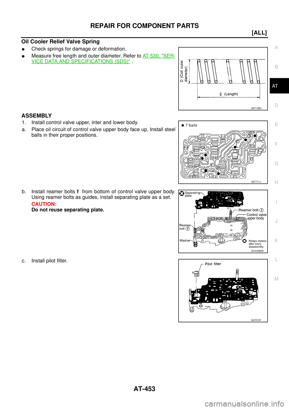
Oil Cooler Relief Valve Spring
�Check springs for damage or deformation.
�Measure free length and outer diameter. Refer to AT- 5 3 0 , "SER-
VICE DATA AND SPECIFICATIONS (SDS)" .
ASSEMBLY
1. Install control valve upper, inter and lower body.
a. Place oil circuit of control valve upper body face up. Install steel
balls in their proper positions.
b. Install reamer bolts f from bottom of control valve upper body.
Using reamer bolts as guides, install separating plate as a set.
CAUTION:
Do not reuse separating plate.
c. Install pilot filter.
SAT138D
SAT771J
SCIA4980E
SAT074F
Page 2718 of 4555
AT-454
[ALL]
REPAIR FOR COMPONENT PARTS
d. Place control valve inter body as shown in the figure (side of
control valve lower body face up). Install steel balls in their
proper positions.
e. Install control valve inter body on control valve upper body using
reamer bolts f as guides.
CAUTION:
Be careful not to dislocate or drop steel balls.
f. Install check balls and oil cooler relief valve springs in their
proper positions in control valve lower body.
g. Install bolts e from bottom of control valve lower body. Using
bolts e as guides, install separating plate as a set.
CAUTION:
Do not reuse separating plate.
h. Install support plates on control valve lower body.
i. Install control valve lower body on control valve inter body using
reamer bolts f as guides and tighten reamer bolts f slightly.
SAT705J
SCIA4981E
SAT110DA
SCIA4982E
SCIA5669E
Page 2722 of 4555
![NISSAN X-TRAIL 2005 Service Repair Manual AT-458
[ALL]
REPAIR FOR COMPONENT PARTS
DISASSEMBLY
1. Remove valves at retainer plates.
CAUTION:
Do not use a magnetic pick-up tool.
a. Use a screwdriver to remove retainer plates.
b. Remove retain](/manual-img/5/57403/w960_57403-2721.png "NISSAN X-TRAIL 2005 Service Repair Manual AT-458
[ALL]
REPAIR FOR COMPONENT PARTS
DISASSEMBLY
1. Remove valves at retainer plates.
CAUTION:
Do not use a magnetic pick-up tool.
a. Use a screwdriver to remove retainer plates.
b. Remove retain")
AT-458
[ALL]
REPAIR FOR COMPONENT PARTS
DISASSEMBLY
1. Remove valves at retainer plates.
CAUTION:
Do not use a magnetic pick-up tool.
a. Use a screwdriver to remove retainer plates.
b. Remove retainer plates while holding spring, plugs or sleeves.
CAUTION:
Remove plugs slowly to prevent internal parts from jumping
out.
1. Retainer plate 2. Plug 3. Cooler check valve spring
4. Cooler check valve 5. Control valve upper body 6. Pilot valve
7. Pilot valve spring 8. Retainer plate 9. 1-2 accumulator retainer plate
10. 1-2 accumulator piston spring 11. 1-2 accumulator piston 12. Plug
13. Retainer plate 14. Retainer plate 15. Plug
16. 1st reducing valve 17. 1st reducing valve spring 18. Retainer plate
19. 3-2 timing valve spring 20. 3-2 timing valve 21. Retainer plate
22. Plug 23. Overrun clutch reducing valve 24. Overrun clutch reducing valve spring
25. Retainer plate 26. Torque converter relief valve spring 27. Torque converter relief valve
28. Retainer plate 29. Sleeve 30. Plug
31. Torque converter clutch control valve
spring32. Torque converter clutch control
valve33. Retainer plate
34. Plug 35. 1-2 accumulator valve spring 36. 1-2 accumulator valve
SCIA4979E
SAT553G
SAT554G
![NISSAN X-TRAIL 2005 Service Repair Manual AT-448
[ALL]
REPAIR FOR COMPONENT PARTS
Control Valve AssemblyECS00EC1
COMPONENTS
1. Oil strainer 2. O-ring 3. Snap ring
4. Terminal body 5. O-ring 6. Solenoid valve assembly
7. Control valve lower](/manual-img/5/57403/w960_57403-2711.png "NISSAN X-TRAIL 2005 Service Repair Manual AT-448
[ALL]
REPAIR FOR COMPONENT PARTS
Control Valve AssemblyECS00EC1
COMPONENTS
1. Oil strainer 2. O-ring 3. Snap ring
4. Terminal body 5. O-ring 6. Solenoid valve assembly
7. Control valve lower")
![NISSAN X-TRAIL 2005 Service Repair Manual AT-450
[ALL]
REPAIR FOR COMPONENT PARTS
3. Remove O-rings from solenoid valves and terminal body.
4. Place control valve upper body facedown, and remove bolts b ,
and nut f .
CAUTION:
Remove bolts w](/manual-img/5/57403/w960_57403-2713.png "NISSAN X-TRAIL 2005 Service Repair Manual AT-450
[ALL]
REPAIR FOR COMPONENT PARTS
3. Remove O-rings from solenoid valves and terminal body.
4. Place control valve upper body facedown, and remove bolts b ,
and nut f .
CAUTION:
Remove bolts w")
![NISSAN X-TRAIL 2005 Service Repair Manual REPAIR FOR COMPONENT PARTS
AT-451
[ALL]
D
E
F
G
H
I
J
K
L
MA
B
AT
9. Remove control valve inter body from control valve upper body.
10. Check to see that steel balls are properly positioned in contr](/manual-img/5/57403/w960_57403-2714.png "NISSAN X-TRAIL 2005 Service Repair Manual REPAIR FOR COMPONENT PARTS
AT-451
[ALL]
D
E
F
G
H
I
J
K
L
MA
B
AT
9. Remove control valve inter body from control valve upper body.
10. Check to see that steel balls are properly positioned in contr")
![NISSAN X-TRAIL 2005 Service Repair Manual AT-454
[ALL]
REPAIR FOR COMPONENT PARTS
d. Place control valve inter body as shown in the figure (side of
control valve lower body face up). Install steel balls in their
proper positions.
e. Install](/manual-img/5/57403/w960_57403-2717.png "NISSAN X-TRAIL 2005 Service Repair Manual AT-454
[ALL]
REPAIR FOR COMPONENT PARTS
d. Place control valve inter body as shown in the figure (side of
control valve lower body face up). Install steel balls in their
proper positions.
e. Install")