2005 NISSAN NAVARA Vacuum pump
[x] Cancel search: Vacuum pumpPage 335 of 3171

ATC-1
AUTOMATIC AIR CONDITIONER
J AIR CONDITIONER
CONTENTS
C
D
E
F
G
H
I
K
L
M
SECTIONAT C
A
B
AT C
AUTOMATIC AIR CONDITIONER
PRECAUTIONS .......................................................... 4
Precautions for Supplemental Restraint System
(SRS)“AIRBAG”and“SEATBELTPRE-TEN-
SIONER” .................................................................. 4
Precautions for Working with HFC-134a (R-134a)..... 4
Contaminated Refrigerant ........................................ 4
General Refrigerant Precautions .............................. 5
Precautions for Refrigerant Connection ................... 5
ABOUT ONE-TOUCH JOINT ................................ 5
FEATURES OF NEW TYPE REFRIGERANT
CONNECTION ...................................................... 7
O-RING AND REFRIGERANT CONNECTION..... 9
Precautions for Servicing Compressor ................... 12
Precautions for Service Equipment ........................ 12
RECOVERY/RECYCLING EQUIPMENT ............ 12
ELECTRONIC LEAK DETECTOR ...................... 12
VACUUM PUMP ................................................. 13
MANIFOLD GAUGE SET .................................... 13
SERVICE HOSES ............................................... 13
SERVICE COUPLERS ........................................ 14
REFRIGERANT WEIGHT SCALE ...................... 14
CALIBRATING ACR4 WEIGHT SCALE .............. 14
CHARGING CYLINDER ...................................... 14
Precautions for Leak Detection Dye ....................... 14
IDENTIFICATION ................................................ 15
IDENTIFICATION LABEL FOR VEHICLE ........... 15
Wiring Diagrams and Trouble Diagnosis ................ 15
PREPARATION ......................................................... 16
Special Service Tools ............................................. 16
HFC-134a (R-134a) Service Tools and Equipment... 16
Commercial Service Tools ...................................... 19
REFRIGERATION SYSTEM ..................................... 20
Refrigerant Cycle ................................................... 20
REFRIGERANT FLOW ....................................... 20
FREEZE PROTECTION ..................................... 20
Refrigerant System Protection ............................... 20
REFRIGERANT PRESSURE SENSOR ............. 20
PRESSURE RELIEF VALVE ............................... 21
Components ........................................................... 22
REFRIGERATION SYSTEM ............................... 22LUBRICANT .............................................................. 24
Maintenance of Lubricant Quantity in Compressor... 24
LUBRICANT ........................................................ 24
CHECKING AND ADJUSTING ............................ 24
AIR CONDITIONER CONTROL ............................... 26
Description .............................................................. 26
Operation ................................................................ 26
AIR MIX DOORS CONTROL .............................. 26
BLOWER SPEED CONTROL ............................. 26
INTAKE DOOR CONTROL ................................. 26
MODE DOOR CONTROL ................................... 26
DEFROSTER DOOR CONTROL ........................ 26
MAGNET CLUTCH CONTROL ........................... 27
SELF-DIAGNOSTIC SYSTEM ............................ 27
Description of Control System ................................ 28
Control Operation ................................................... 28
DISPLAY SCREEN .............................................. 29
AUTO SWITCH ................................................... 29
TEMPERATURE CONTROL DIAL (TEMPERA-
TURE CONTROL) (DRIVER SIDE) ..................... 29
TEMPERATURE CONTROL DIAL (TEMPERA-
TURE CONTROL) (PASSENGER SIDE) ............ 29
TEMPERATURE CONTROL DIAL (TEMPERA-
TURE AND MODE CONTROL) (REAR) ............. 29
RECIRCULATION (REC) SWITCH ..................... 29
DEFROSTER (DEF) SWITCH ............................. 29
REAR WINDOW DEFOGGER SWITCH ............. 29
OFF SWITCH ...................................................... 29
A/C SWITCH ....................................................... 29
MODE SWITCH (FRONT) ................................... 29
FRONT BLOWER CONTROL DIAL .................... 29
MODE SWITCH (REAR) ..................................... 29
Discharge Air Flow ................................................. 30
FRONT ................................................................ 30
System Description ................................................. 31
SWITCHES AND THEIR CONTROL FUNCTION... 31
CAN Communication System Description .............. 32
TROUBLE DIAGNOSIS ............................................ 33
CONSULT-II Function (BCM) ................................. 33
CONSULT-II BASIC OPERATION ....................... 33
Page 347 of 3171
PRECAUTIONS
ATC-13
C
D
E
F
G
H
I
K
L
MA
B
AT C
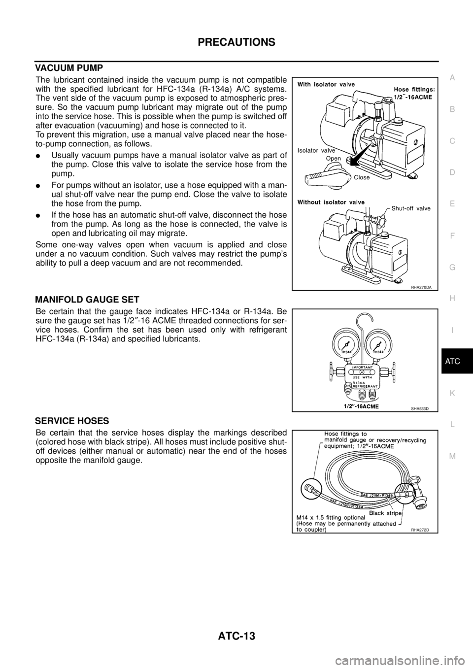
VACUUM PUMP
The lubricant contained inside the vacuum pump is not compatible
with the specified lubricant for HFC-134a (R-134a) A/C systems.
The vent side of the vacuum pump is exposed to atmospheric pres-
sure. So the vacuum pump lubricant may migrate out of the pump
into the service hose. This is possible when the pump is switched off
after evacuation (vacuuming) and hose is connected to it.
To prevent this migration, use a manual valve placed near the hose-
to-pump connection, as follows.
lUsually vacuum pumps have a manual isolator valve as part of
the pump. Close this valve to isolate the service hose from the
pump.
lFor pumps without an isolator, use a hose equipped with a man-
ual shut-off valve near the pump end. Close the valve to isolate
the hose from the pump.
lIf the hose has an automatic shut-off valve, disconnect the hose
from the pump. As long as the hose is connected, the valve is
open and lubricating oil may migrate.
Some one-way valves open when vacuum is applied and close
under a no vacuum condition. Such valves may restrict the pump’s
ability to pull a deep vacuum and are not recommended.
MANIFOLD GAUGE SET
Be certain that the gauge face indicates HFC-134a or R-134a. Be
sure the gauge set has 1/2²-16 ACME threaded connections for ser-
vice hoses. Confirm the set has been used only with refrigerant
HFC-134a (R-134a) and specified lubricants.
SERVICE HOSES
Be certain that the service hoses display the markings described
(colored hose with black stripe). All hoses must include positive shut-
off devices (either manual or automatic) near the end of the hoses
opposite the manifold gauge.
RHA270DA
SHA533D
RHA272D
Page 352 of 3171
ATC-18
PREPARATION
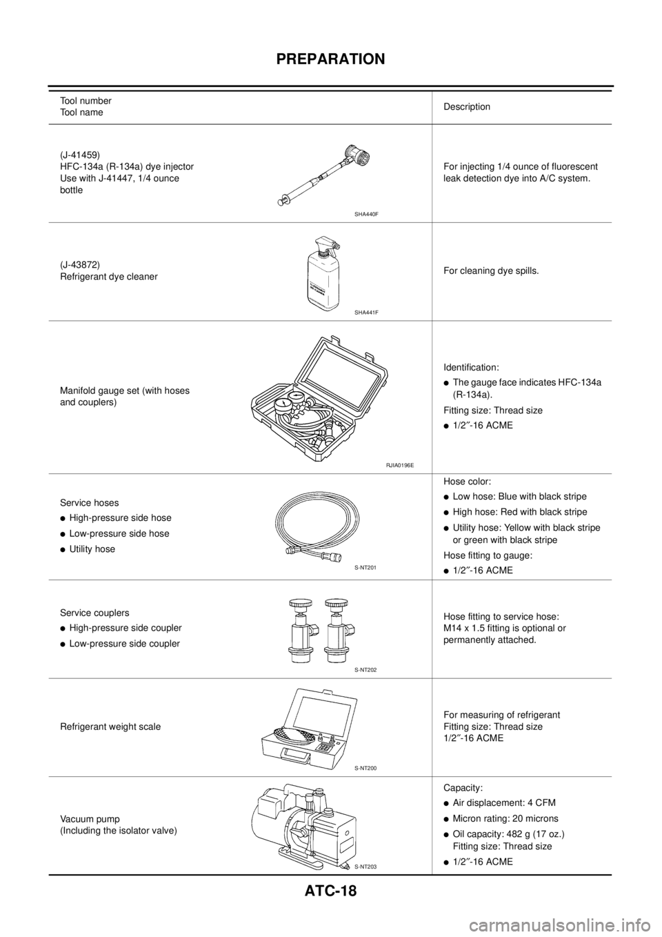
(J-41459)
HFC-134a (R-134a) dye injector
Use with J-41447, 1/4 ounce
bottleFor injecting 1/4 ounce of fluorescent
leak detection dye into A/C system.
(J-43872)
Refrigerant dye cleanerFor cleaning dye spills.
Manifold gauge set (with hoses
and couplers)Identification:
lThe gauge face indicates HFC-134a
(R-134a).
Fitting size: Thread size
l1/2²-16 ACME
Service hoses
lHigh-pressure side hose
lLow-pressure side hose
lUtility hoseHose color:
lLow hose: Blue with black stripe
lHigh hose: Red with black stripe
lUtility hose: Yellow with black stripe
or green with black stripe
Hose fitting to gauge:
l1/2²-16 ACME
Service couplers
lHigh-pressure side coupler
lLow-pressure side couplerHose fitting to service hose:
M14 x 1.5 fitting is optional or
permanently attached.
Refrigerant weight scaleFor measuring of refrigerant
Fitting size: Thread size
1/2²-16 ACME
Vacuum pump
(Including the isolator valve)Capacity:
lAir displacement: 4 CFM
lMicron rating: 20 microns
lOil capacity: 482 g (17 oz.)
Fitting size: Thread size
l1/2²-16 ACME Tool number
Tool nameDescription
SHA440F
SHA441F
RJIA0196E
S-NT201
S-NT202
S-NT200
S-NT203
Page 473 of 3171
REFRIGERANT LINES
ATC-139
C
D
E
F
G
H
I
K
L
MA
B
AT C
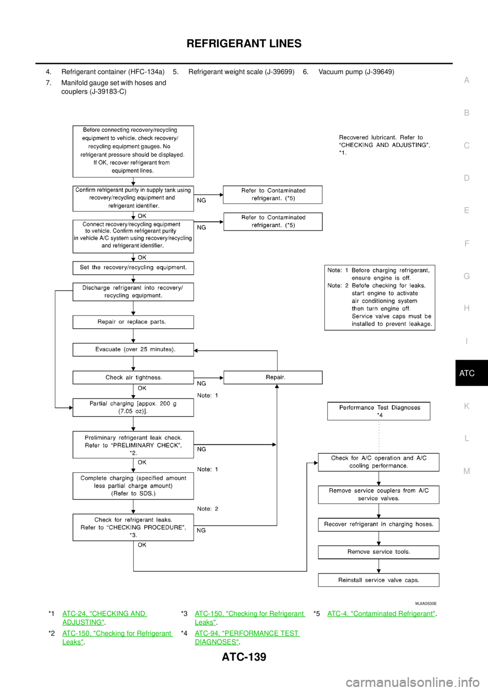
4. Refrigerant container (HFC-134a) 5. Refrigerant weight scale (J-39699) 6. Vacuum pump (J-39649)
7. Manifold gauge set with hoses and
couplers (J-39183-C)
*1AT C - 2 4 , "
CHECKING AND
ADJUSTING".*3ATC-150, "
Checking for Refrigerant
Leaks".*5AT C - 4 , "
Contaminated Refrigerant".
*2ATC-150, "
Checking for Refrigerant
Leaks".*4ATC-94, "
PERFORMANCE TEST
DIAGNOSES".
WJIA0530E
Page 806 of 3171
BR-20
BRAKE BOOSTER
Removal and Installation
EFS005SU
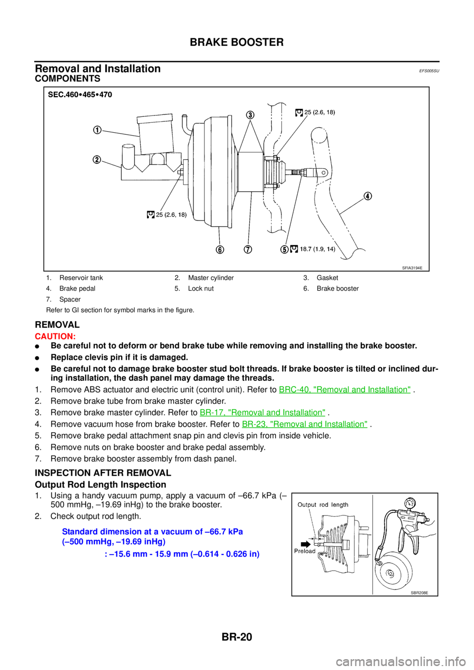
COMPONENTS
REMOVAL
CAUTION:
lBe careful not to deform or bend brake tube while removing and installing the brake booster.
lReplace clevis pin if it is damaged.
lBe careful not to damage brake booster stud bolt threads. If brake booster is tilted or inclined dur-
ing installation, the dash panel may damage the threads.
1. Remove ABS actuator and electric unit (control unit). Refer toBRC-40, "
Removal and Installation".
2. Remove brake tube from brake master cylinder.
3. Remove brake master cylinder. Refer toBR-17, "
Removal and Installation".
4. Remove vacuum hose from brake booster. Refer toBR-23, "
Removal and Installation".
5. Remove brake pedal attachment snap pin and clevis pin from inside vehicle.
6. Remove nuts on brake booster and brake pedal assembly.
7. Remove brake booster assembly from dash panel.
INSPECTION AFTER REMOVAL
Output Rod Length Inspection
1. Using a handy vacuum pump, apply a vacuum of –66.7 kPa (–
500 mmHg, –19.69 inHg) to the brake booster.
2. Check output rod length.
1. Reservoir tank 2. Master cylinder 3. Gasket
4. Brake pedal 5. Lock nut 6. Brake booster
7. Spacer
Refer to GI section for symbol marks in the figure.
SFIA3194E
Standard dimension at a vacuum of –66.7 kPa
(–500 mmHg, –19.69 inHg)
: –15.6 mm - 15.9 mm (–0.614 - 0.626 in)
SBR208E
Page 808 of 3171
BR-22
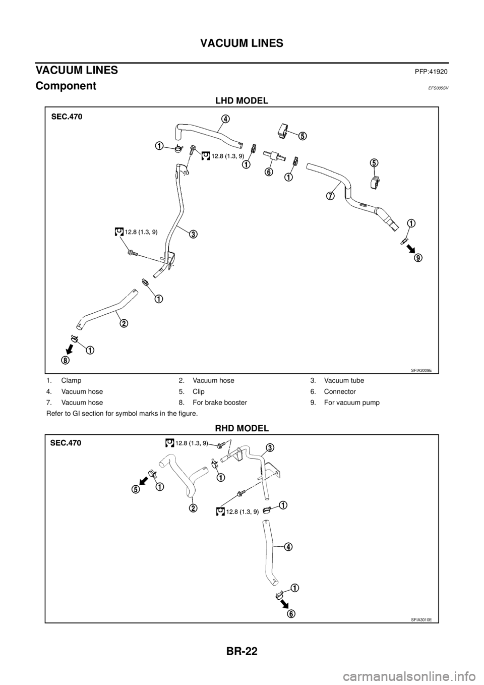
VACUUM LINES
VACUUM LINES
PFP:41920
ComponentEFS005SV
LHD MODEL
RHD MODEL
SFIA3009E
1. Clamp 2. Vacuum hose 3. Vacuum tube
4. Vacuum hose 5. Clip 6. Connector
7. Vacuum hose 8. For brake booster 9. For vacuum pump
Refer to GI section for symbol marks in the figure.
SFIA3010E
Page 809 of 3171
VACUUM LINES
BR-23
C
D
E
G
H
I
J
K
L
MA
B
BR
Removal and InstallationEFS005SW
CAUTION:
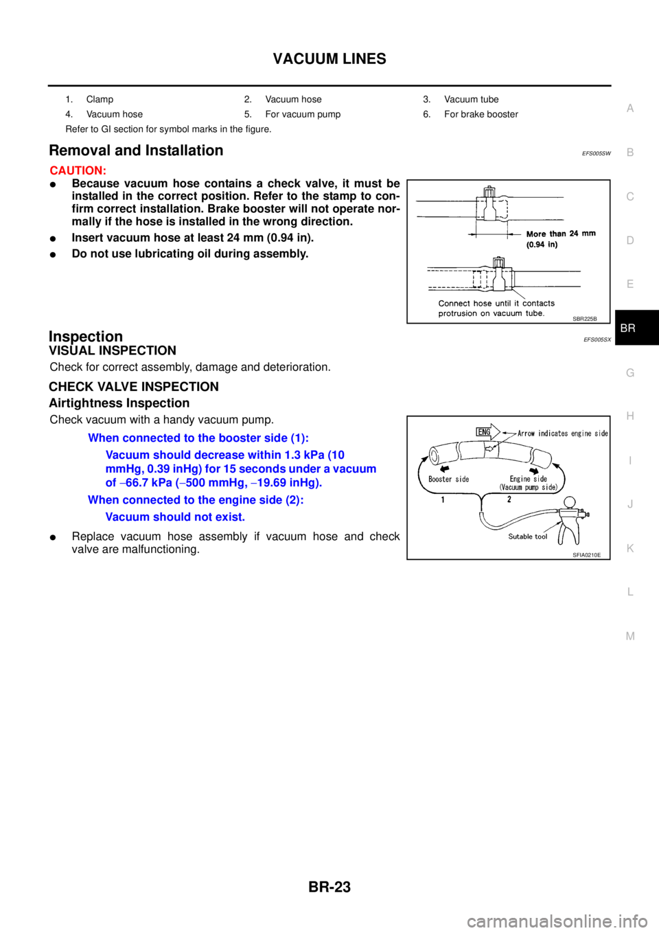
lBecause vacuum hose contains a check valve, it must be
installed in the correct position. Refer to the stamp to con-
firm correct installation. Brake booster will not operate nor-
mally if the hose is installed in the wrong direction.
lInsert vacuum hose at least 24 mm (0.94 in).
lDo not use lubricating oil during assembly.
InspectionEFS005SX
VISUAL INSPECTION
Check for correct assembly, damage and deterioration.
CHECK VALVE INSPECTION
Airtightness Inspection
Check vacuum with a handy vacuum pump.
lReplace vacuum hose assembly if vacuum hose and check
valve are malfunctioning.
1. Clamp 2. Vacuum hose 3. Vacuum tube
4. Vacuum hose 5. For vacuum pump 6. For brake booster
Refer to GI section for symbol marks in the figure.
SBR225B
When connected to the booster side (1):
Vacuum should decrease within 1.3 kPa (10
mmHg, 0.39 inHg) for 15 seconds under a vacuum
of-66.7 kPa (-500 mmHg,-19.69 inHg).
When connected to the engine side (2):
Vacuum should not exist.
SFIA0210E
Page 981 of 3171

EC-1
ENGINE CONTROL SYSTEM
B ENGINE
CONTENTS
C
D
E
F
G
H
I
J
K
L
M
SECTIONEC
A
EC
ENGINE CONTROL SYSTEM
INDEX FOR DTC ........................................................ 6
DTC No. Index ......................................................... 6
Alphabetical Index .................................................... 8
PRECAUTIONS ........................................................ 10
Precautions for Supplemental Restraint System
(SRS)“AIRBAG”and“SEATBELTPRE-TEN-
SIONER” ................................................................ 10
On Board Diagnostic (OBD) System of Engine ...... 10
Precautions ............................................................ 10
Wiring Diagrams and Trouble Diagnosis ................ 13
PREPARATION ......................................................... 14
Special Service Tools ............................................. 14
Commercial Service Tools ...................................... 14
ENGINE CONTROL SYSTEM .................................. 15
System Diagram ..................................................... 15
Vacuum Hose Drawing ........................................... 16
System Chart ......................................................... 18
Fuel Injection Control System ................................ 18
Fuel Injection Timing Control System ..................... 20
Air Conditioning Cut Control ................................... 20
Fuel Cut Control (At No Load & High Engine Speed)... 20
Crankcase Ventilation System ............................... 21
CAN Communication .............................................. 22
BASIC SERVICE PROCEDURE .............................. 23
Fuel Filter ............................................................... 23
Fuel Pump Learning Value Clearing ...................... 24
Injector Adjustment Value Registration .................. 25
ON BOARD DIAGNOSTIC (OBD) SYSTEM ............ 27
DTC Detection Logic .............................................. 27
Diagnostic Trouble Code (DTC) ............................. 27
Freeze Frame Data ................................................ 28
NATS (Nissan Anti-theft System) ........................... 28
Malfunction Indicator (MI) ....................................... 28
Relationship Between MI, DTC, CONSULT-II and
Driving Patterns ...................................................... 31
TROUBLE DIAGNOSIS ............................................ 33
Trouble Diagnosis Introduction ............................... 33
DTC Inspection Priority Chart ................................ 37
Basic Inspection ..................................................... 38
Symptom Matrix Chart ........................................... 42Engine Control Component Parts Location ............ 46
Circuit Diagram ....................................................... 50
ECM Harness Connector Terminal Layout ............. 52
ECM Terminals And Reference Value .................... 52
CONSULT-II Function (ENGINE) ............................ 59
CONSULT-II Reference Value in Data Monitor Mode
... 66
Major Sensor Reference Graph in Data Monitor
Mode ....................................................................... 69
TROUBLE DIAGNOSIS FOR INTERMITTENT INCI-
DENT ......................................................................... 70
Description .............................................................. 70
Diagnostic Procedure ............................................. 70
POWER SUPPLY AND GROUND CIRCUIT ............. 71
ECM Terminals and Reference Value ..................... 71
Wiring Diagram ....................................................... 72
Diagnostic Procedure ............................................. 73
Ground Inspection .................................................. 78
DTC U1000 CAN COMMUNICATION LINE .............. 79
Description .............................................................. 79
On Board Diagnosis Logic ...................................... 79
DTC Confirmation Procedure ................................. 79
Wiring Diagram ....................................................... 80
Diagnostic Procedure ............................................. 81
DTC P0016 CKP - CMP CORRELATION ................. 82
On Board Diagnosis Logic ...................................... 82
DTC Confirmation Procedure ................................. 82
Diagnostic Procedure ............................................. 82
DTC P0088 FUEL SYSTEM ...................................... 84
On Board Diagnosis Logic ...................................... 84
DTC Confirmation Procedure ................................. 84
Diagnostic Procedure ............................................. 84
Removal and Installation ........................................ 85
DTC P0089 FUEL PUMP .......................................... 86
On Board Diagnosis Logic ...................................... 86
DTC Confirmation Procedure ................................. 86
Diagnostic Procedure ............................................. 87
Removal and Installation ........................................ 87
DTC P0093 FUEL SYSTEM ...................................... 88
On Board Diagnosis Logic ...................................... 88