Page 1114 of 3171
EC-134
DTC P0217 ENGINE OVER TEMPERATURE
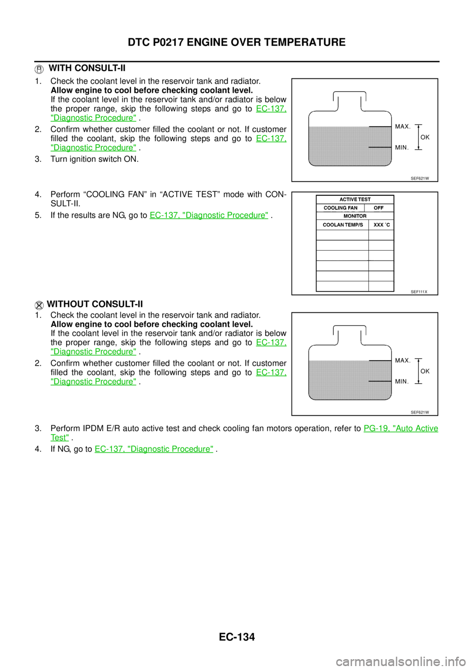
WITH CONSULT-II
1. Check the coolant level in the reservoir tank and radiator.
Allow engine to cool before checking coolant level.
If the coolant level in the reservoir tank and/or radiator is below
the proper range, skip the following steps and go toEC-137,
"Diagnostic Procedure".
2. Confirm whether customer filled the coolant or not. If customer
filled the coolant, skip the following steps and go toEC-137,
"Diagnostic Procedure".
3. Turn ignition switch ON.
4. Perform “COOLING FAN” in “ACTIVE TEST” mode with CON-
SULT-II.
5. If the results are NG, go toEC-137, "
Diagnostic Procedure".
WITHOUT CONSULT-II
1. Check the coolant level in the reservoir tank and radiator.
Allow engine to cool before checking coolant level.
If the coolant level in the reservoir tank and/or radiator is below
the proper range, skip the following steps and go toEC-137,
"Diagnostic Procedure".
2. Confirm whether customer filled the coolant or not. If customer
filled the coolant, skip the following steps and go toEC-137,
"Diagnostic Procedure".
3. Perform IPDM E/R auto active test and check cooling fan motors operation, refer toPG-19, "
Auto Active
Te s t".
4. If NG, go toEC-137, "
Diagnostic Procedure".
SEF621W
SEF111X
SEF621W
Page 1117 of 3171
DTC P0217 ENGINE OVER TEMPERATURE
EC-137
C
D
E
F
G
H
I
J
K
L
MA
EC
Diagnostic ProcedureEBS01KFP
1.CHECK COOLING FAN (CRANKSHAFT DRIVEN) OPERATION
1. Start engine and let it idle.
2. Make sure that cooling fan (crankshaft driven) operates normally.
OK or NG
OK (With CONSULT-II)>>GO TO 2.
OK (Without CONSULT-II)>>GO TO 3.
NG >> Check cooling fan (crankshaft driven). Refer toCO-19, "
Removal and Installation".
2.CHECK COOLING FAN OPERATION
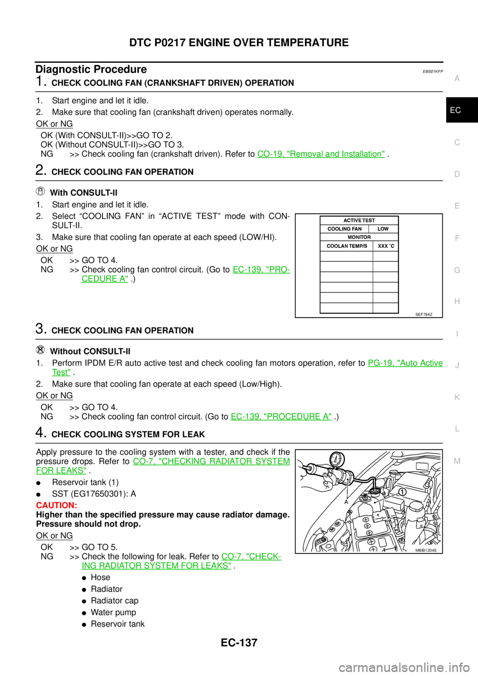
With CONSULT-II
1. Start engine and let it idle.
2. Select “COOLING FAN” in “ACTIVE TEST” mode with CON-
SULT-II.
3. Make sure that cooling fan operate at each speed (LOW/HI).
OK or NG
OK >> GO TO 4.
NG >> Check cooling fan control circuit. (Go toEC-139, "
PRO-
CEDURE A".)
3.CHECK COOLING FAN OPERATION
Without CONSULT-II
1. Perform IPDM E/R auto active test and check cooling fan motors operation, refer toPG-19, "
Auto Active
Te s t".
2. Make sure that cooling fan operate at each speed (Low/High).
OK or NG
OK >> GO TO 4.
NG >> Check cooling fan control circuit. (Go toEC-139, "
PROCEDURE A".)
4.CHECK COOLING SYSTEM FOR LEAK
Apply pressure to the cooling system with a tester, and check if the
pressure drops. Refer toCO-7, "
CHECKING RADIATOR SYSTEM
FOR LEAKS".
lReservoir tank (1)
lSST (EG17650301): A
CAUTION:
Higher than the specified pressure may cause radiator damage.
Pressure should not drop.
OK or NG
OK >> GO TO 5.
NG >> Check the following for leak. Refer toCO-7, "
CHECK-
ING RADIATOR SYSTEM FOR LEAKS".
lHose
lRadiator
lRadiator cap
lWater pump
lReservoir tank
SEF784Z
MBIB1204E
Page 1119 of 3171
DTC P0217 ENGINE OVER TEMPERATURE
EC-139
C
D
E
F
G
H
I
J
K
L
MA
EC
PROCEDURE A
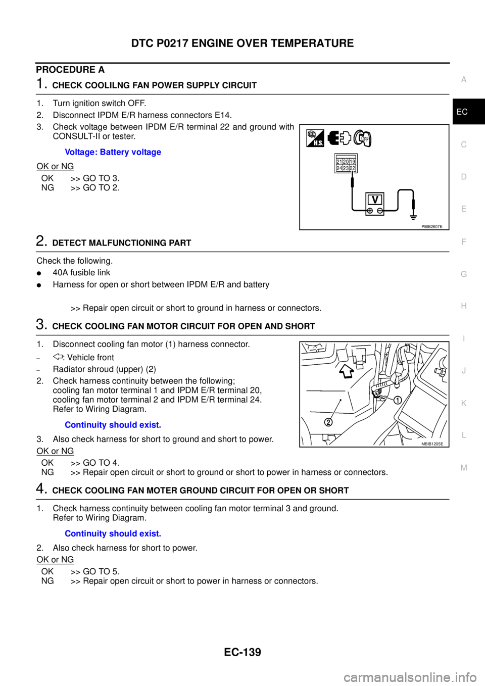
1.CHECK COOLILNG FAN POWER SUPPLY CIRCUIT
1. Turn ignition switch OFF.
2. Disconnect IPDM E/R harness connectors E14.
3. Check voltage between IPDM E/R terminal 22 and ground with
CONSULT-II or tester.
OK or NG
OK >> GO TO 3.
NG >> GO TO 2.
2.DETECT MALFUNCTIONING PART
Check the following.
l40A fusible link
lHarness for open or short between IPDM E/R and battery
>> Repair open circuit or short to ground in harness or connectors.
3.CHECK COOLING FAN MOTOR CIRCUIT FOR OPEN AND SHORT
1. Disconnect cooling fan motor (1) harness connector.
–: Vehicle front
–Radiator shroud (upper) (2)
2. Check harness continuity between the following;
cooling fan motor terminal 1 and IPDM E/R terminal 20,
cooling fan motor terminal 2 and IPDM E/R terminal 24.
Refer to Wiring Diagram.
3. Also check harness for short to ground and short to power.
OK or NG
OK >> GO TO 4.
NG >> Repair open circuit or short to ground or short to power in harness or connectors.
4.CHECK COOLING FAN MOTER GROUND CIRCUIT FOR OPEN OR SHORT
1. Check harness continuity between cooling fan motor terminal 3 and ground.
Refer to Wiring Diagram.
2. Also check harness for short to power.
OK or NG
OK >> GO TO 5.
NG >> Repair open circuit or short to power in harness or connectors.Voltage: Battery voltage
PBIB2607E
Continuity should exist.
MBIB1205E
Continuity should exist.
Page 1120 of 3171
EC-140
DTC P0217 ENGINE OVER TEMPERATURE
5.CHECK COOLING FAN MOTOR
Refer toEC-141, "
Component Inspection".
OK or NG
OK >> GO TO 6.
NG >> Replace cooling fan motors.
6.CHECK INTERMITTENT INCIDENT
PerformEC-70, "
TROUBLE DIAGNOSIS FOR INTERMITTENT INCIDENT".
OK or NG
OK >> Replace IPDM E/R. Refer toPG-14, "IPDM E/R (INTELLIGENT POWER DISTRIBUTION MOD-
ULE ENGINE ROOM)".
NG >> Repair or replace harness or connector.
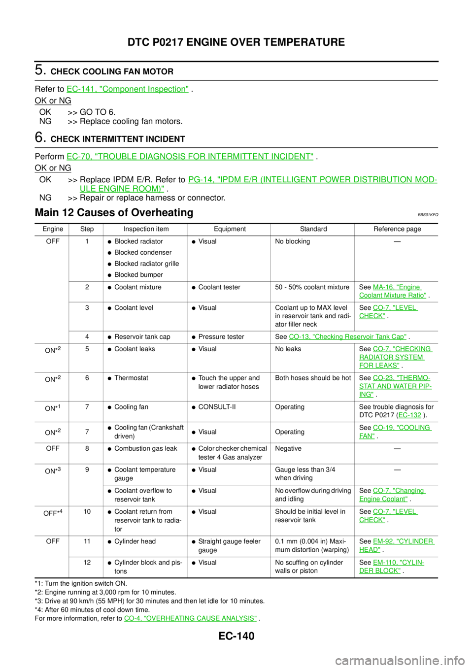
Main 12 Causes of OverheatingEBS01KFQ
*1: Turn the ignition switch ON.
*2: Engine running at 3,000 rpm for 10 minutes.
*3: Drive at 90 km/h (55 MPH) for 30 minutes and then let idle for 10 minutes.
*4: After 60 minutes of cool down time.
For more information, refer toCO-4, "
OVERHEATING CAUSE ANALYSIS". Engine Step Inspection item Equipment Standard Reference page
OFF 1
lBlocked radiator
lBlocked condenser
lBlocked radiator grille
lBlocked bumper
lVisual No blocking —
2
lCoolant mixturelCoolant tester 50 - 50% coolant mixture SeeMA-16, "Engine
Coolant Mixture Ratio".
3
lCoolant levellVisual Coolant up to MAX level
in reservoir tank and radi-
ator filler neckSeeCO-7, "LEVEL
CHECK".
4
lReservoir tank caplPressure tester SeeCO-13, "Checking Reservoir Tank Cap".
ON*
25lCoolant leakslVisual No leaks SeeCO-7, "CHECKING
RADIATOR SYSTEM
FOR LEAKS".
ON*
26lThermostatlTouch the upper and
lower radiator hosesBoth hoses should be hot SeeCO-23, "THERMO-
STAT AND WATER PIP-
ING".
ON*
17lCooling fanlCONSULT-II Operating See trouble diagnosis for
DTC P0217 (EC-132
).
ON*
27lCooling fan (Crankshaft
driven)lVisual OperatingSeeCO-19, "COOLING
FA N".
OFF 8
lCombustion gas leaklColor checker chemical
tester 4 Gas analyzerNegative —
ON*
39lCoolant temperature
gaugelVisual Gauge less than 3/4
when driving—
lCoolant overflow to
reservoir tanklVisual No overflow during driving
and idlingSeeCO-7, "Changing
Engine Coolant".
OFF*
410lCoolant return from
reservoir tank to radia-
torlVisual Should be initial level in
reservoir tankSeeCO-7, "LEVEL
CHECK".
OFF 11
lCylinder headlStraight gauge feeler
gauge0.1 mm (0.004 in) Maxi-
mum distortion (warping)SeeEM-92, "CYLINDER
HEAD".
12
lCylinder block and pis-
tonslVisual No scuffing on cylinder
walls or pistonSeeEM-110, "CYLIN-
DER BLOCK".
Page 1347 of 3171
SQUEAK AND RATTLE TROUBLE DIAGNOSES
EI-9
C
D
E
F
G
H
J
K
L
MA
B
EI
SEATS
When isolating seat noise it's important to note the position the seat is in and the load placed on the seat when
the noise is present. These conditions should be duplicated when verifying and isolating the cause of the
noise.
Cause of seat noise include:
1. Headrest rods and holder
2. A squeak between the seat pad cushion and frame
3. The rear seatback lock and bracket
These noises can be isolated by moving or pressing on the suspected components while duplicating the con-
ditions under which the noise occurs. Most of these incidents can be repaired by repositioning the component
or applying urethane tape to the contact area.
UNDERHOOD
Some interior noise may be caused by components under the hood or on the engine wall. The noise is then
transmitted into the passenger compartment.
Causes of transmitted underhood noise include:
1. Any component mounted to the engine wall
2. Components that pass through the engine wall
3. Engine wall mounts and connectors
4. Loose radiator mounting pins
5. Hood bumpers out of adjustment
6. Hood striker out of adjustment
These noises can be difficult to isolate since they cannot be reached from the interior of the vehicle. The best
method is to secure, move or insulate one component at a time and test drive the vehicle. Also, engine RPM
or load can be changed to isolate the noise. Repairs can usually be made by moving, adjusting, securing, or
insulating the component causing the noise.
Page 1353 of 3171
FRONT BUMPER
EI-15
C
D
E
F
G
H
J
K
L
MA
B
EI
FRONT BUMPERPFP:F2022
Removal and InstallationEIS00DY9
FRONT BUMPER
Removal
1. Remove radiator grille. Refer toEI-19, "FRONT GRILLE".
2. Remove front center spoiler, then LH and RH front side spoiler.
3. Remove front undercover.
4. Remove front LH/RH mudguard. Refer toEI-23, "
MUDGUARD".
1. Front bumper assembly 2. Front head lamp washer nozzle
(if equipped)3. Front spoiler RH/LH
4. Front spoiler center 5. Front license plate bracket 6. Front engine undercover
7. Fog lamp (if equipped) 8. Fog lamp opening finisher
(if equipped)9. Front bumper stay LH
10. Front bumper reinforcement 11. Front bumper stay RH 12. Front bumper bracket RH
13. Front bumper bracket LH 14. Front bumper bracket center 15. Front bumper, absorber shock
LH/RH
16. Front bumper fascia retainer 17. Front bumper reinforcement RH/LH
MIIB9121E
Page 1401 of 3171
CHARGE AIR COOLER
EM-19
C
D
E
F
G
H
I
J
K
L
MA
EM
INSPECTION AFTER REMOVAL
Check air passages of charge air cooler core and fins for clogging, leaks or deformation. Clean or replace
charge air cooler if necessary.
lBe careful not to deform core fins.
lFor cleaning procedure of charge air cooler core, refer toCO-13, "Checking Radiator".
INSTALLATION
Note the following, and install in the reverse order of removal.
lPay attention to identification mark color and direction when installing air inlet hose.
lAlign marks. Attach each joint. Screw clamps firmly.
Page 1455 of 3171
SECONDARY TIMING CHAIN
EM-73
C
D
E
F
G
H
I
J
K
L
MA
EM
SECONDARY TIMING CHAINPFP:13028
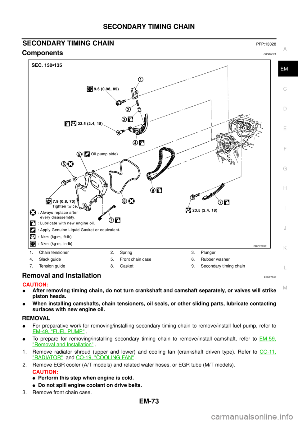
ComponentsEBS01EKA
Removal and InstallationEBS01E68
CAUTION:
lAfter removing timing chain, do not turn crankshaft and camshaft separately, or valves will strike
piston heads.
lWhen installing camshafts, chain tensioners, oil seals, or other sliding parts, lubricate contacting
surfaces with new engine oil.
REMOVAL
lFor preparative work for removing/installing secondary timing chain to remove/install fuel pump, refer to
EM-49, "
FUEL PUMP".
lTo prepare for removing/installing secondary timing chain to remove/install camshaft, refer toEM-59,
"Removal and Installation".
1. Remove radiator shroud (upper and lower) and cooling fan (crankshaft driven type). Refer toCO-11,
"RADIATOR"andCO-19, "COOLING FAN".
2. Remove EGR cooler (A/T models) and related water hoses, or EGR tube (M/T models).
CAUTION:
lPerform this step when engine is cold.
lDo not spill engine coolant on drive belts.
3. Remove front chain case.
1. Chain tensioner 2. Spring 3. Plunger
4. Slack guide 5. Front chain case 6. Rubber washer
7. Tension guide 8. Gasket 9. Secondary timing chain
PBIC2326E