2005 NISSAN NAVARA radiator
[x] Cancel search: radiatorPage 2276 of 3171
MA-1
MAINTENANCE
L MAINTENANCE
CONTENTS
C
D
E
F
G
H
I
J
K
M
SECTIONMA
A
B
MA
MAINTENANCE
PRECAUTIONS .......................................................... 3
Precautions for Supplemental Restraint System
(SRS)“AIRBAG”and“SEATBELTPRE-TEN-
SIONER” .................................................................. 3
PREPARATION ........................................................... 4
Special Service Tools ............................................... 4
Commercial Service Tools ........................................ 4
DESCRIPTION ............................................................ 5
Pre-Delivery Inspection Items .................................. 5
GENERAL MAINTENANCE ....................................... 7
General Maintenance ............................................... 7
PERIODIC MAINTENANCE ....................................... 8
Periodic Maintenance ............................................... 8
ENGINE AND EMISSION CONTROL MAINTE-
NANCE (YD25DDTI DIESEL ENGINE) ................ 8
CHASSIS AND BODY MAINTENANCE
(YD25DDTI DIESEL ENGINE) .............................. 9
MAINTENANCE UNDER SEVERE DRIVING
CONDITIONS ...................................................... 10
ENGINE AND EMISSION CONTROL MAINTE-
NANCE (YD25DDTI DIESEL ENGINE) ............... 11
CHASSIS AND BODY MAINTENANCE
(YD25DDTI DIESEL ENGINE) ............................. 11
MAINTENANCE UNDER SEVERE DRIVING
CONDITIONS ...................................................... 13
RECOMMENDED FLUIDS AND LUBRICANTS ...... 14
Fluids and Lubricants ............................................. 14
SAE Viscosity Number ........................................... 15
DIESEL ENGINE ................................................. 15
GEAR OIL ........................................................... 15
Engine Coolant Mixture Ratio ................................ 16
ENGINE MAINTENANCE ......................................... 17
Checking Drive Belts .............................................. 17
Deflection Adjustment ............................................ 18
POWER STEERING OIL PUMP BELT ............... 18
A/C COMPRESSOR, ALTERNATOR AND
WATER PUMP BELT .......................................... 19
Changing Engine Coolant ...................................... 19
DRAINING ENGINE COOLANT ......................... 19
REFILLING ENGINE COOLANT ........................ 20FLUSHING COOLING SYSTEM ......................... 21
Checking Cooling System ...................................... 21
CHECKING COOLING SYSTEM HOSES ........... 21
CHECKING RADIATOR ...................................... 21
CHECKING RESERVOIR TANK CAP ................. 21
CHECKING RADIATOR SYSTEM FOR LEAKS... 22
Checking Fuel Lines ............................................... 23
Changing Fuel Filter ............................................... 23
REMOVAL ........................................................... 23
INSTALLATION ................................................... 24
INSPECTION AFTER INSTALLATION ................ 24
Draining Water from Fuel Filter .............................. 25
Changing Engine Air Cleaner Filter ........................ 25
DRY PAPER TYPE .............................................. 25
Changing Engine Oil ............................................... 25
Changing Oil Filter .................................................. 26
REMOVAL ........................................................... 26
INSTALLATION ................................................... 26
INSPECTION AFTER INSTALLATION ................ 27
CHASSIS AND BODY MAINTENANCE ................... 28
Checking the Exhaust System ................................ 28
Checking Clutch Fluid Level and Leaks ................. 28
Checking Clutch System ........................................ 28
Checking M/T Oil .................................................... 28
Changing M/T Oil .................................................... 29
Checking A/T Fluid ................................................. 29
Changing A/T Fluid ................................................. 31
Checking Transfer Fluid ......................................... 31
FLUID LEAKAGE AND FLUID LEVEL ................ 31
Changing Transfer Fluid ......................................... 32
DRAINING ........................................................... 32
FILLING ............................................................... 32
Checking Propeller Shaft ........................................ 32
Checking Front Final Drive Oil (Front Differential
Gear Oil) ................................................................. 32
OIL LEAKAGE AND OIL LEVEL ......................... 32
Changing Front Final Drive Oil (Front Differential
Gear Oil) ................................................................. 33
DRAINING ........................................................... 33
FILLING ............................................................... 33
Page 2279 of 3171
MA-4
PREPARATION
PREPARATION
PFP:00002
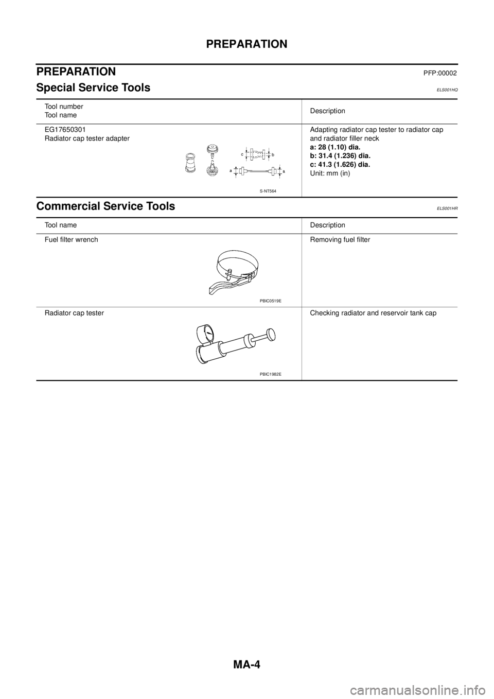
Special Service ToolsELS001HQ
Commercial Service ToolsELS001HR
Tool number
Tool nameDescription
EG17650301
Radiator cap tester adapterAdapting radiator cap tester to radiator cap
and radiator filler neck
a: 28 (1.10) dia.
b: 31.4 (1.236) dia.
c: 41.3 (1.626) dia.
Unit: mm (in)
S-NT564
Tool nameDescription
Fuel filter wrench Removing fuel filter
Radiator cap tester Checking radiator and reservoir tank cap
PBIC0519E
PBIC1982E
Page 2291 of 3171
MA-16
RECOMMENDED FLUIDS AND LUBRICANTS
Engine Coolant Mixture Ratio
ELS001JC
The engine cooling system is filled at the factory with a high-quality,
year-round and extended life engine coolant. The high quality engine
coolant contains the specific solutions effective for the anti-corrosion
and the anti-freeze function. Therefore, additional cooling system
additives are not necessary.
CAUTION:
lWhen adding or replacing coolant, be sure to use only Gen-
uine NISSAN Anti-freeze Coolant (L250) or equivalent in its
quality. Because L250 is premixed type coolant.
The use of other types of engine coolant may damage your
cooling system.
lWhen checking the engine coolant mixture ratio by the coolant
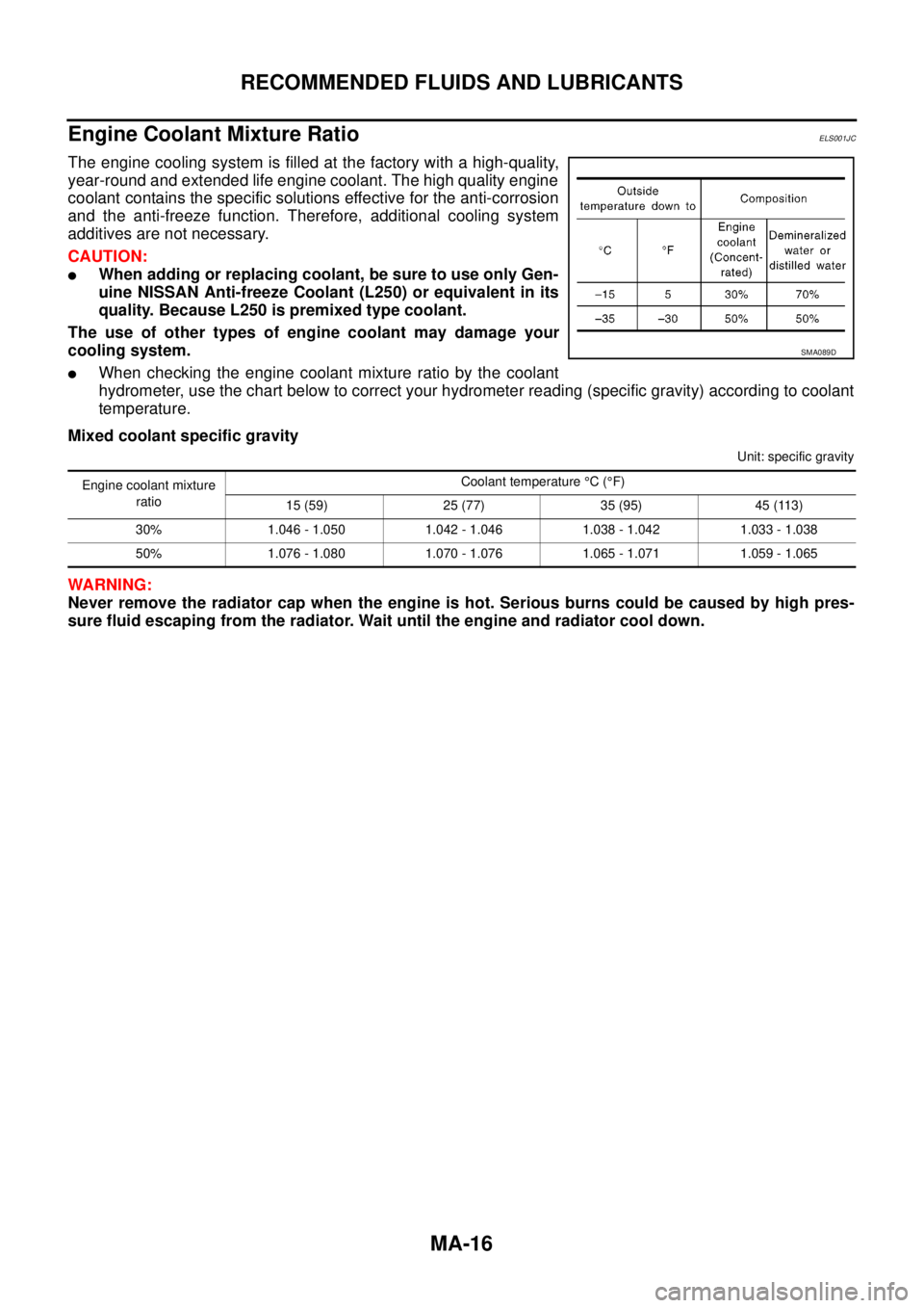
hydrometer, use the chart below to correct your hydrometer reading (specific gravity) according to coolant
temperature.
Mixed coolant specific gravity
Unit: specific gravity
WARNING:
Never remove the radiator cap when the engine is hot. Serious burns could be caused by high pres-
sure fluid escaping from the radiator. Wait until the engine and radiator cool down.
SMA089D
Engine coolant mixture
ratioCoolant temperature°C(°F)
15 (59) 25 (77) 35 (95) 45 (113)
30% 1.046 - 1.050 1.042 - 1.046 1.038 - 1.042 1.033 - 1.038
50% 1.076 - 1.080 1.070 - 1.076 1.065 - 1.071 1.059 - 1.065
Page 2294 of 3171
ENGINE MAINTENANCE
MA-19
C
D
E
F
G
H
I
J
K
MA
B
MA
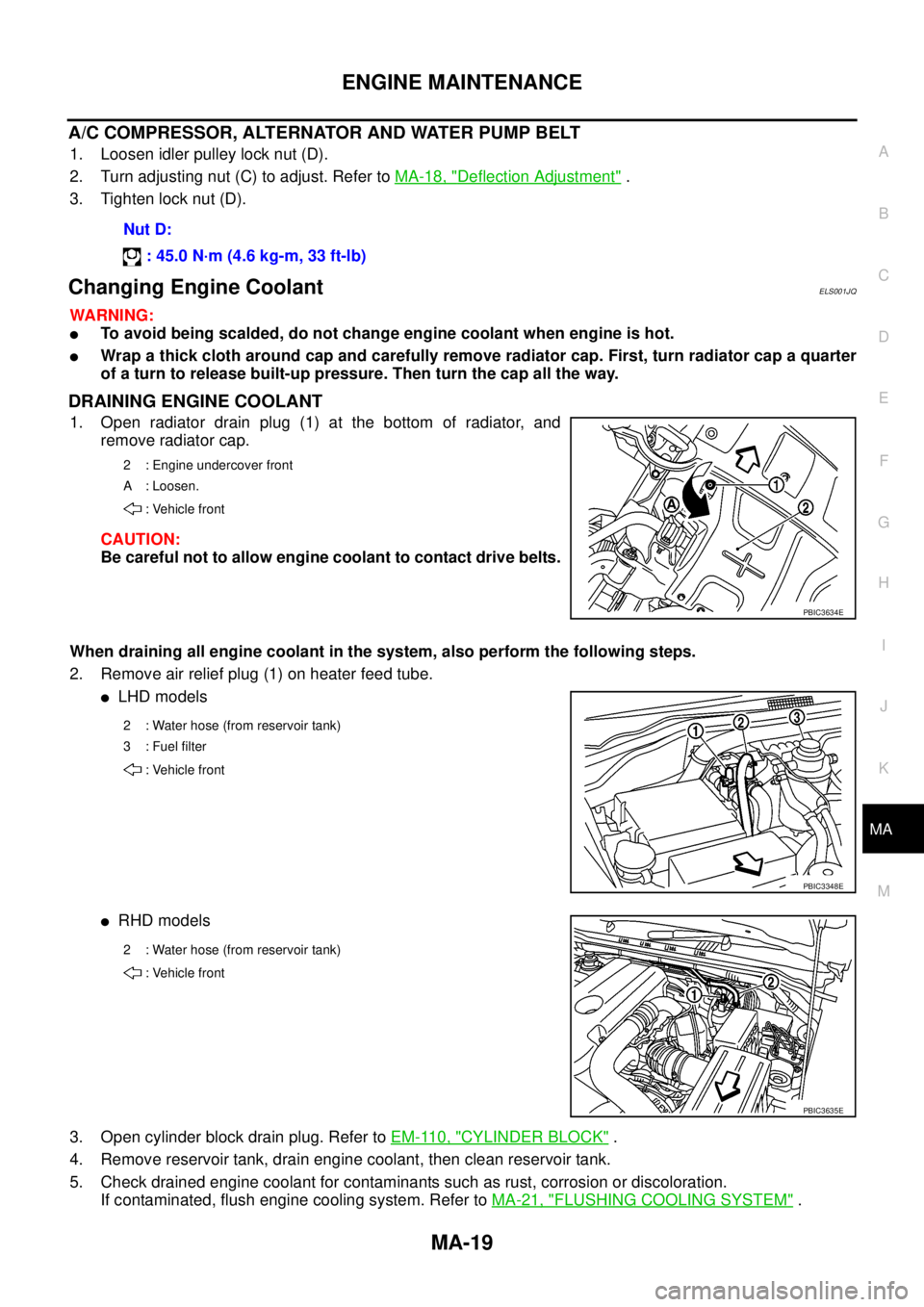
A/C COMPRESSOR, ALTERNATOR AND WATER PUMP BELT
1. Loosen idler pulley lock nut (D).
2. Turn adjusting nut (C) to adjust. Refer toMA-18, "
Deflection Adjustment".
3. Tighten lock nut (D).
Changing Engine CoolantELS001JQ
WARNING:
lTo avoid being scalded, do not change engine coolant when engine is hot.
lWrap a thick cloth around cap and carefully remove radiator cap. First, turn radiator cap a quarter
of a turn to release built-up pressure. Then turn the cap all the way.
DRAINING ENGINE COOLANT
1. Open radiator drain plug (1) at the bottom of radiator, and
remove radiator cap.
CAUTION:
Be careful not to allow engine coolant to contact drive belts.
When draining all engine coolant in the system, also perform the following steps.
2. Remove air relief plug (1) on heater feed tube.
lLHD models
lRHD models
3. Open cylinder block drain plug. Refer toEM-110, "
CYLINDER BLOCK".
4. Remove reservoir tank, drain engine coolant, then clean reservoir tank.
5. Check drained engine coolant for contaminants such as rust, corrosion or discoloration.
If contaminated, flush engine cooling system. Refer toMA-21, "
FLUSHING COOLING SYSTEM". Nut D:
: 45.0 N·m (4.6 kg-m, 33 ft-lb)
2 : Engine undercover front
A : Loosen.
: Vehicle front
PBIC3634E
2 : Water hose (from reservoir tank)
3:Fuelfilter
: Vehicle front
PBIC3348E
2 : Water hose (from reservoir tank)
: Vehicle front
PBIC3635E
Page 2295 of 3171
MA-20
ENGINE MAINTENANCE
REFILLING ENGINE COOLANT
1. Install reservoir tank, and radiator drain plug.
CAUTION:
Be sure to clean radiator drain plug and install with new O-ring.
lIf water drain plug on cylinder block is removed, close and tighten it. Refer toEM-110, "CYLIN-
DER BLOCK".
2. Make sure that each hose clamp has been firmly tightened.
3. Fill radiator and reservoir tank to the specified level.
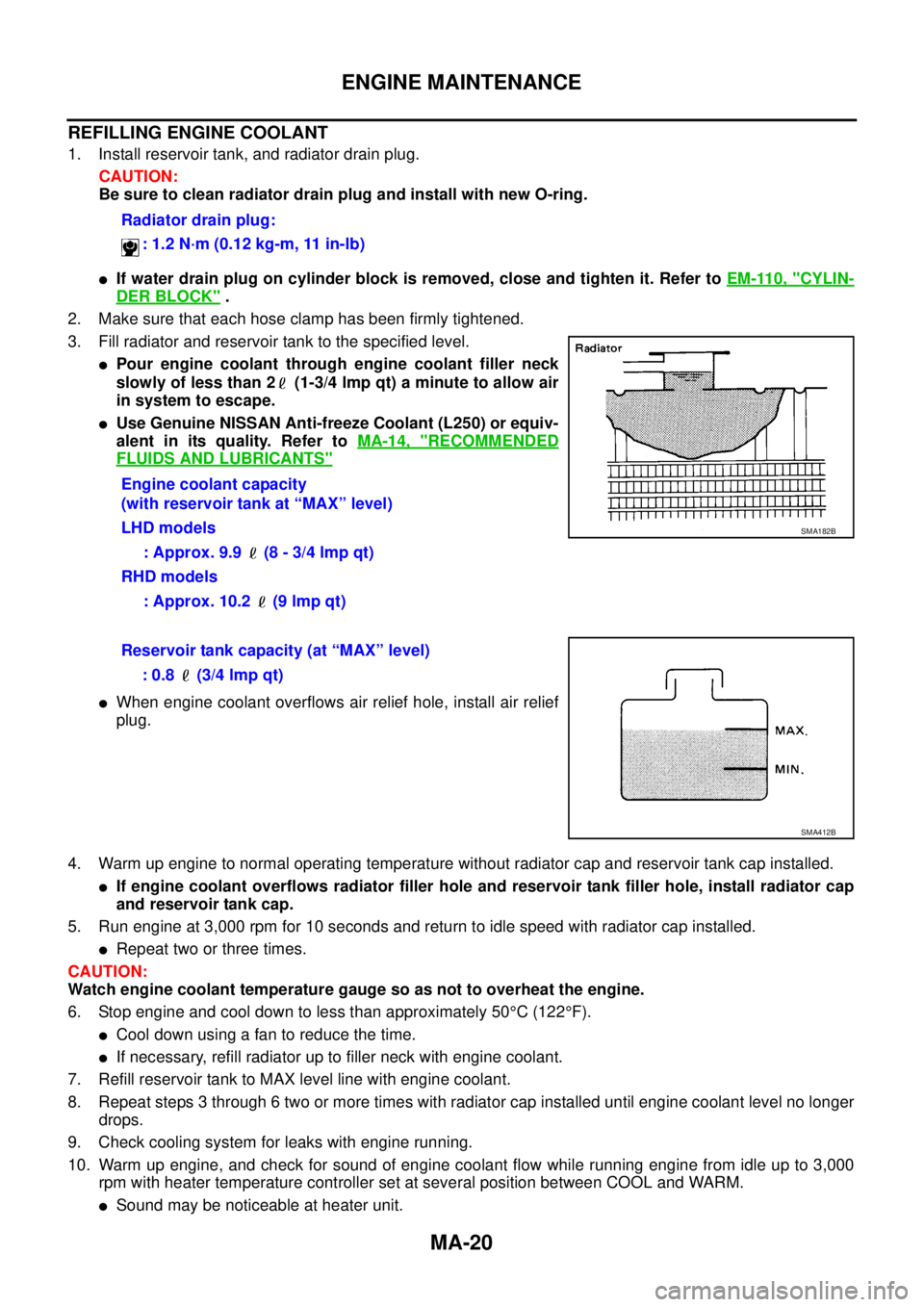
lPour engine coolant through engine coolant filler neck
slowly of less than 2 (1-3/4 lmp qt) a minute to allow air
in system to escape.
lUse Genuine NISSAN Anti-freeze Coolant (L250) or equiv-
alent in its quality. Refer toMA-14, "
RECOMMENDED
FLUIDS AND LUBRICANTS"
lWhen engine coolant overflows air relief hole, install air relief
plug.
4. Warm up engine to normal operating temperature without radiator cap and reservoir tank cap installed.
lIf engine coolant overflows radiator filler hole and reservoir tank filler hole, install radiator cap
and reservoir tank cap.
5. Run engine at 3,000 rpm for 10 seconds and return to idle speed with radiator cap installed.
lRepeat two or three times.
CAUTION:
Watch engine coolant temperature gauge so as not to overheat the engine.
6. Stop engine and cool down to less than approximately 50°C(122°F).
lCool down using a fan to reduce the time.
lIf necessary, refill radiator up to filler neck with engine coolant.
7. Refill reservoir tank to MAX level line with engine coolant.
8. Repeat steps 3 through 6 two or more times with radiator cap installed until engine coolant level no longer
drops.
9. Check cooling system for leaks with engine running.
10. Warm up engine, and check for sound of engine coolant flow while running engine from idle up to 3,000
rpm with heater temperature controller set at several position between COOL and WARM.
lSound may be noticeable at heater unit.Radiator drain plug:
: 1.2 N·m (0.12 kg-m, 11 in-lb)
Engine coolant capacity
(with reservoir tank at “MAX” level)
LHD models
: Approx. 9.9 (8 - 3/4 lmp qt)
RHD models
: Approx. 10.2 (9 lmp qt)
SMA182B
Reservoir tank capacity (at “MAX” level)
: 0.8 (3/4 lmp qt)
SMA412B
Page 2296 of 3171
ENGINE MAINTENANCE
MA-21
C
D
E
F
G
H
I
J
K
MA
B
MA
11. Repeat step 10 three times.
12. If sound is heard, bleed air from cooling system by repeating steps 3 through 6 until engine coolant level
no longer drops.
FLUSHING COOLING SYSTEM
1. Fill radiator with water until water spills from the air relief hole, then close air relief plug. Fill radiator and
reservoir tank with water and reinstall radiator cap and reservoir tank cap.
2. Run engine and warm it up to normal operating temperature.
3. Rev engine two or three times under no-load.
4. Stop engine and wait until it cools down.
5. Drain water from the system. Refer toMA-19, "
DRAINING ENGINE COOLANT".
6. Repeat steps 1 through 5 until clear water begins to drain from radiator.
Checking Cooling SystemELS001JR
WARNING:
Never remove the radiator cap and reservoir tank cap when the engine is hot. Serious burns could
occur from high pressure engine coolant escaping from the radiator and the reservoir tank. Wrap a
thick cloth around the cap. Slowly turn it a quarter turn to allow built-up pressure to escape. Carefully
remove the cap by turning it all the way.
CHECKING COOLING SYSTEM HOSES
Check hoses for improper attachment, leaks, cracks, damage, loose connections, chafing and deterioration.
CHECKING RADIATOR
Check radiator for mud or clogging. If necessary, clean radiator as follows.
lBe careful not to bend or damage the radiator fins.
lWhen radiator is cleaned without removal, remove all surrounding parts such as cooling fan, radiator
shroud and horns. Then tape the harness and connectors to prevent water from entering.
1. Apply water by hose to the back side of the radiator core vertically downwards.
2. Apply water again to all radiator core surface once per minute.
3. Stop washing if any stains no longer flow out from the radiator.
4. Blow air into the back side of radiator core vertically downwards.
lUse compressed air lower than 490 kpa (4.9 bar, 5 kg/cm2, 71psi) and keep distance more than 30
cm(11.8 in).
5. Blow air again into all the radiator core surface once per minute until no water sprays out.
CHECKING RESERVOIR TANK CAP
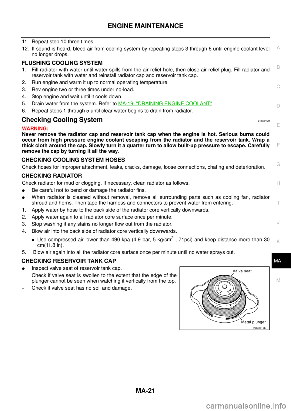
lInspect valve seat of reservoir tank cap.
–Check if valve seat is swollen to the extent that the edge of the
plunger cannot be seen when watching it vertically from the top.
–Check if valve seat has no soil and damage.
PBIC2816E
Page 2297 of 3171
MA-22
ENGINE MAINTENANCE
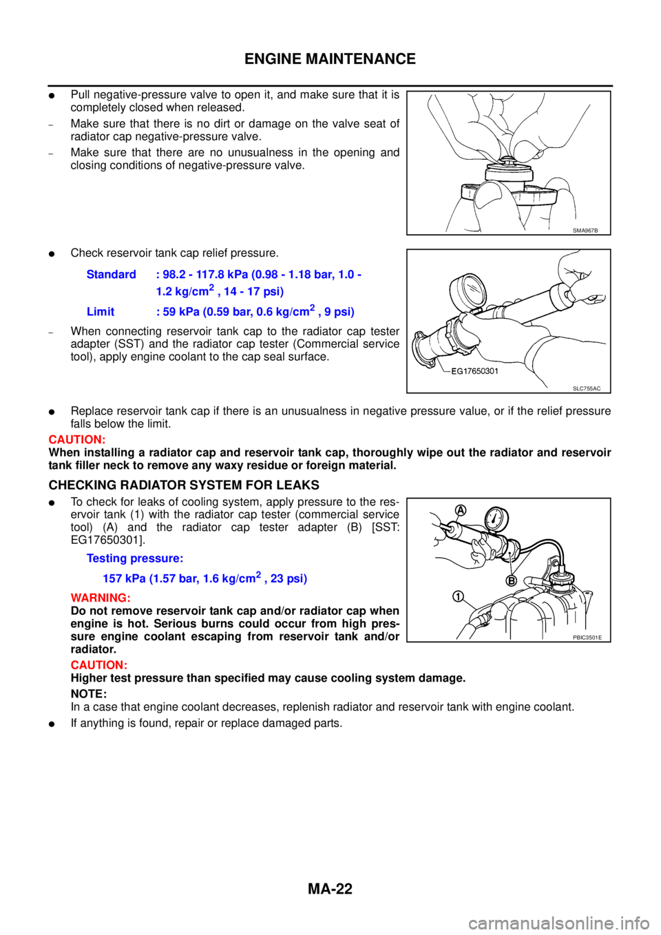
lPull negative-pressure valve to open it, and make sure that it is
completely closed when released.
–Makesurethatthereisnodirtordamageonthevalveseatof
radiator cap negative-pressure valve.
–Make sure that there are no unusualness in the opening and
closing conditions of negative-pressure valve.
lCheck reservoir tank cap relief pressure.
–When connecting reservoir tank cap to the radiator cap tester
adapter (SST) and the radiator cap tester (Commercial service
tool), apply engine coolant to the cap seal surface.
lReplace reservoir tank cap if there is an unusualness in negative pressure value, or if the relief pressure
falls below the limit.
CAUTION:
When installing a radiator cap and reservoir tank cap, thoroughly wipe out the radiator and reservoir
tank filler neck to remove any waxy residue or foreign material.
CHECKING RADIATOR SYSTEM FOR LEAKS
lTo check for leaks of cooling system, apply pressure to the res-
ervoir tank (1) with the radiator cap tester (commercial service
tool) (A) and the radiator cap tester adapter (B) [SST:
EG17650301].
WARNING:
Do not remove reservoir tank cap and/or radiator cap when
engine is hot. Serious burns could occur from high pres-
sure engine coolant escaping from reservoir tank and/or
radiator.
CAUTION:
Higher test pressure than specified may cause cooling system damage.
NOTE:
In a case that engine coolant decreases, replenish radiator and reservoir tank with engine coolant.
lIf anything is found, repair or replace damaged parts.
SMA967B
Standard : 98.2 - 117.8 kPa (0.98 - 1.18 bar, 1.0 -
1.2 kg/cm
2,14-17psi)
Limit : 59 kPa (0.59 bar, 0.6 kg/cm
2,9psi)
SLC755AC
Testing pressure:
157 kPa (1.57 bar, 1.6 kg/cm
2,23psi)
PBIC3501E
Page 2305 of 3171
MA-30
CHASSIS AND BODY MAINTENANCE
NOTE:
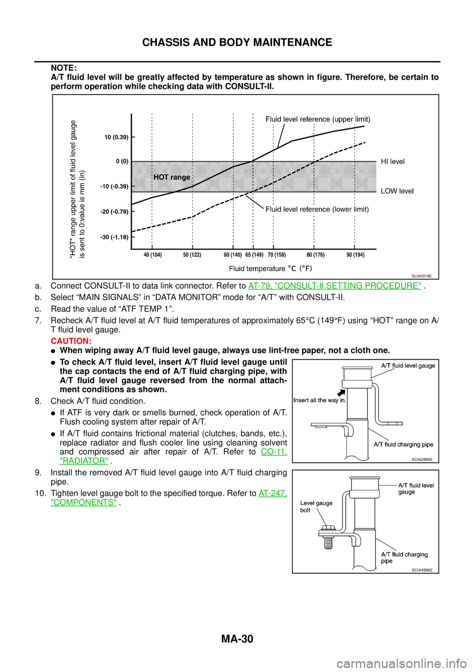
A/T fluid level will be greatly affected by temperature as shown in figure. Therefore, be certain to
perform operation while checking data with CONSULT-II.
a. Connect CONSULT-II to data link connector. Refer toAT-79, "
CONSULT-II SETTING PROCEDURE".
b. Select “MAIN SIGNALS” in “DATA MONITOR” mode for “A/T” with CONSULT-II.
c. Readthevalueof“ATFTEMP1”.
7. Recheck A/T fluid level at A/T fluid temperatures of approximately 65°C(149°F)using“HOT”rangeonA/
T fluid level gauge.
CAUTION:
lWhen wiping away A/T fluid level gauge, always use lint-free paper, not a cloth one.
lTo check A/T fluid level, insert A/T fluid level gauge until
the cap contacts the end of A/T fluid charging pipe, with
A/T fluid level gauge reversed from the normal attach-
ment conditions as shown.
8. Check A/T fluid condition.
lIf ATF is very dark or smells burned, check operation of A/T.
Flush cooling system after repair of A/T.
lIf A/T fluid contains frictional material (clutches, bands, etc.),
replace radiator and flush cooler line using cleaning solvent
and compressed air after repair of A/T. Refer toCO-11,
"RADIATOR".
9. Install the removed A/T fluid level gauge into A/T fluid charging
pipe.
10. Tighten level gauge bolt to the specified torque. Refer toAT-247,
"COMPONENTS".
SLIA0016E
SCIA2899E
SCIA4896E