2005 NISSAN NAVARA radiator
[x] Cancel search: radiatorPage 2514 of 3171

REFRIGERANT LINES
MTC-127
C
D
E
F
G
H
I
K
L
MA
B
MTC
CAUTION:
lReplace the O-ring of the high-pressure pipe with a new one, then apply compressor oil to it when
installing it.
lAfter charging refrigerant, check for leaks.
Removal and Installation for Low-pressure PipeEJS005HH
REMOVAL
1. Discharge the refrigerant. Refer toMTC-118, "HFC-134a (R-134a) Service Procedure".
2. Remove the cowl top and the cowl top extension. Refer toEI-20, "
COWL TOP".
3. Remove the low-pressure pipe. Refer toMTC-120, "
Components".
CAUTION:
Cap or wrap the joint of the pipes with suitable material such as vinyl tape to avoid the entry of air.
INSTALLATION
Installation is in the reverse order of removal.
Refer toMTC-120, "
Components".
CAUTION:
lReplace the O-ring of the high/low-pressure pipe with a new one, then apply compressor oil to it
when installing it.
lAfter charging refrigerant, check for leaks.
Removal and Installation for Refrigerant Pressure SensorEJS005HI
REMOVAL
1. Discharge the refrigerant. Refer toMTC-118, "HFC-134a (R-134a) Service Procedure".
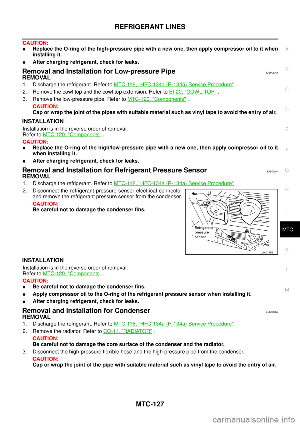
2. Disconnect the refrigerant pressure sensor electrical connector
and remove the refrigerant pressure sensor from the condenser.
CAUTION:
Be careful not to damage the condenser fins.
INSTALLATION
Installation is in the reverse order of removal.
Refer toMTC-120, "
Components".
CAUTION:
lBe careful not to damage the condenser fins.
lApply compressor oil to the O-ring of the refrigerant pressure sensor when installing it.
lAfter charging refrigerant, check for leaks.
Removal and Installation for CondenserEJS005HJ
REMOVAL
1. Discharge the refrigerant. Refer toMTC-118, "HFC-134a (R-134a) Service Procedure".
2. Remove the radiator. Refer toCO-11, "
RADIATOR".
CAUTION:
Be careful not to damage the core surface of the condenser and the radiator.
3. Disconnect the high-pressure flexible hose and the high-pressure pipe from the condenser.
CAUTION:
Cap or wrap the joint of the pipe with suitable material such as vinyl tape to avoid the entry of air.
LJIA0145E
Page 2652 of 3171

POWER STEERING OIL PUMP
PS-25
C
D
E
F
H
I
J
K
L
MA
B
PS
POWER STEERING OIL PUMPPFP:49110
On-Vehicle Inspection and ServiceEGS001LL
CHECKING RELIEF OIL PRESSURE
CAUTION:
Make sure that belt tension is normal before starting the following procedure.
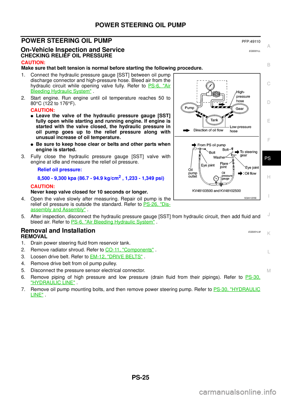
1. Connect the hydraulic pressure gauge [SST] between oil pump
discharge connector and high-pressure hose. Bleed air from the
hydraulic circuit while opening valve fully. Refer toPS-6, "
Air
Bleeding Hydraulic System".
2. Start engine. Run engine until oil temperature reaches 50 to
80°C(122to176°F).
CAUTION:
lLeave the valve of the hydraulic pressure gauge [SST]
fully open while starting and running engine. If engine is
started with the valve closed, the hydraulic pressure in
oil pump goes up to the relief pressure along with
unusual increase of oil temperature.
lBe sure to keep hose clear or belts and other parts when
engineisstarted.
3. Fully close the hydraulic pressure gauge [SST] valve with
engine at idle and measure the relief oil pressure.
CAUTION:
Never keep valve closed for 10 seconds or longer.
4. Open the valve slowly after measuring. Repair oil pump is the
relief oil pressure is outside the standard. Refer toPS-26, "
Dis-
assembly and Assembly".
5. After inspection, disconnect the hydraulic pressure gauge [SST] from hydraulic circuit, then add fluid and
bleed air. Refer toPS-6, "
Air Bleeding Hydraulic System".
Removal and InstallationEGS001LM
REMOVAL
1. Drain power steering fluid from reservoir tank.
2. Remove radiator shroud. Refer toCO-11, "
Components".
3. Loosen drive belt. Refer toEM-12, "
DRIVE BELTS".
4. Remove drive belt from oil pump pulley.
5. Disconnect the pressure sensor electrical connector.
6. Remove piping of high pressure and low pressure (drain fluid from their pipings). Refer toPS-30,
"HYDRAULIC LINE".
7. Remove oil pump mounting bolts, and then remove power steering pump. Refer toPS-30, "
HYDRAULIC
LINE". Relief oil pressure:
8,500 - 9,300 kpa (86.7 - 94.9 kg/cm
2, 1,233 - 1,349 psi)
SGIA1225E
Page 2684 of 3171

SQUEAK AND RATTLE TROUBLE DIAGNOSES
RF-7
C
D
E
F
G
H
J
K
L
MA
B
RF
TRUNK
Trunk noises are often caused by a loose jack or loose items put into the trunk by the owner.
In addition look for:
1. Trunk lid dumpers out of adjustment
2. Trunk lid striker out of adjustment
3. Trunk lid torsion bars knocking together
4. A loose license plate or bracket
Most of these incidents can be repaired by adjusting, securing or insulating the item(s) or component(s) caus-
ing the noise.
SUNROOF/HEADLINING
Noises in the sunroof/headlining area can often be traced to one of the following:
1. Sunroof lid, rail, linkage or seals making a rattle or light knocking noise
2. Sunvisor shaft shaking in the holder
3. Front or rear windshield touching headlining and squeaking
Again, pressing on the components to stop the noise while duplicating the conditions can isolate most of these
incidents. Repairs usually consist of insulating with felt cloth tape.
SEATS
When isolating seat noise it's important to note the position the seat is in and the load placed on the seat when
the noise is present. These conditions should be duplicated when verifying and isolating the cause of the
noise.
Cause of seat noise include:
1. Headrest rods and holder
2. A squeak between the seat pad cushion and frame
3. Rear seatback lock and bracket
These noises can be isolated by moving or pressing on the suspected components while duplicating the con-
ditions under which the noise occurs. Most of these incidents can be repaired by repositioning the component
or applying urethane tape to the contact area.
UNDERHOOD
Some interior noise may be caused by components under the hood or on the engine wall. The noise is then
transmitted into the passenger compartment.
Causes of transmitted underhood noise include:
1. Any component mounted to the engine wall
2. Components that pass through the engine wall
3. Engine wall mounts and connectors
4. Loose radiator mounting pins
5. Hood bumpers out of adjustment
6. Hood striker out of adjustment
These noises can be difficult to isolate since they cannot be reached from the interior of the vehicle. The best
method is to secure, move or insulate one component at a time and test drive the vehicle. Also, engine RPM
or load can be changed to isolate the noise. Repairs can usually be made by moving, adjusting, securing, or
insulating the component causing the noise.
Page 2807 of 3171

RSU-2
PRECAUTIONS
PRECAUTIONS
PFP:00001
PrecautionsEES002JD
lWhen installing rubber parts, final tightening must be carried out under unladen condition* with
tires on ground.
*Fuel, radiator coolant, and engine oil are full. Spare tire, jack, hand tools, and mats are in their
designated positions. Oil will shorten the life of rubber bushings, so wipe off any spilled oil imme-
diately.
lLock nuts are not reusable. Always use new lock nuts for installation. New lock nuts are pre-oiled,
do not apply any additional lubrication.
Page 2815 of 3171

RSU-10
LEAF SPRING
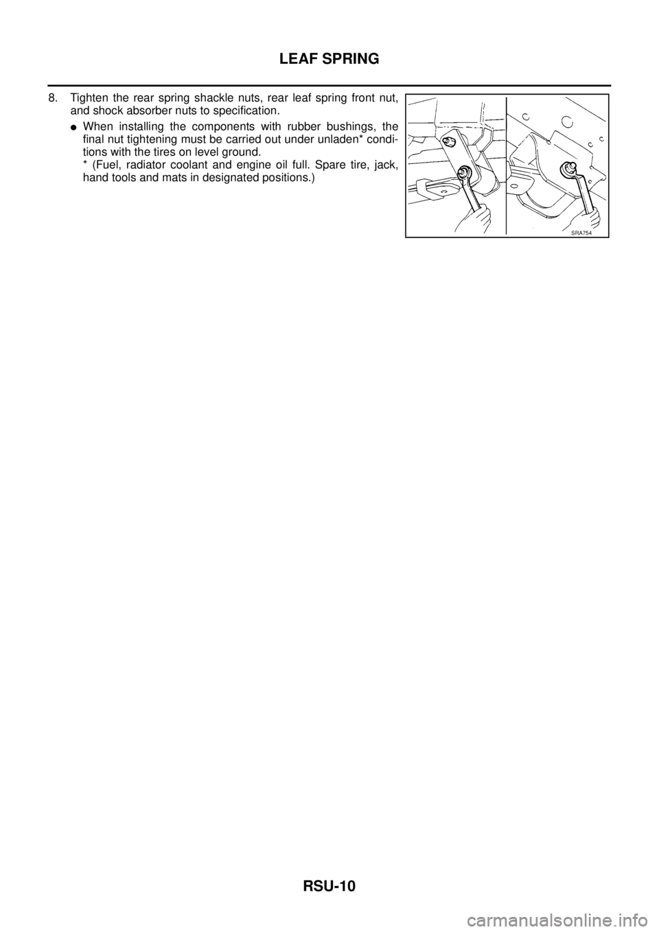
8. Tighten the rear spring shackle nuts, rear leaf spring front nut,
and shock absorber nuts to specification.
lWhen installing the components with rubber bushings, the
final nut tightening must be carried out under unladen* condi-
tions with the tires on level ground.
* (Fuel, radiator coolant and engine oil full. Spare tire, jack,
hand tools and mats in designated positions.)
SRA754
Page 2816 of 3171

SERVICE DATA AND SPECIFICATIONS (SDS)
RSU-11
C
D
F
G
H
I
J
K
L
MA
B
RSU
SERVICE DATA AND SPECIFICATIONS (SDS)PFP:00030
General Specifications (Rear)EES002JK
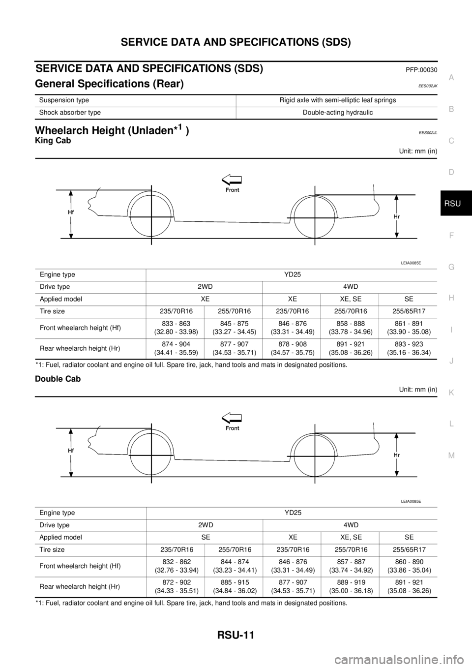
Wheelarch Height (Unladen*1)EES002JL
King Cab
Unit: mm (in)
*1: Fuel, radiator coolant and engine oil full. Spare tire, jack, hand tools and mats in designated positions.
Double Cab
Unit: mm (in)
*1: Fuel, radiator coolant and engine oil full. Spare tire, jack, hand tools and mats in designated positions.Suspension type Rigid axle with semi-elliptic leaf springs
Shock absorber type Double-acting hydraulic
Engine type YD25
Drive type 2WD 4WD
Applied model XE XE XE, SE SE
Tire size 235/70R16 255/70R16 235/70R16 255/70R16 255/65R17
Front wheelarch height (Hf)833 - 863
(32.80 - 33.98)845 - 875
(33.27 - 34.45)846 - 876
(33.31 - 34.49)858 - 888
(33.78 - 34.96)861 - 891
(33.90 - 35.08)
Rear wheelarch height (Hr)874 - 904
(34.41 - 35.59)877 - 907
(34.53 - 35.71)878 - 908
(34.57 - 35.75)891 - 921
(35.08 - 36.26)893 - 923
(35.16 - 36.34)
LEIA0085E
Engine type YD25
Drive type 2WD 4WD
Applied model SE XE XE, SE SE
Tire size 235/70R16 255/70R16 235/70R16 255/70R16 255/65R17
Front wheelarch height (Hf)832 - 862
(32.76 - 33.94)844 - 874
(33.23 - 34.41)846 - 876
(33.31 - 34.49)857 - 887
(33.74 - 34.92)860 - 890
(33.86 - 35.04)
Rear wheelarch height (Hr)872 - 902
(34.33 - 35.51)885 - 915
(34.84 - 36.02)877 - 907
(34.53 - 35.71)889 - 919
(35.00 - 36.18)891 - 921
(35.08 - 36.26)
LEIA0085E
Page 2878 of 3171

SQUEAK AND RATTLE TROUBLE DIAGNOSES
SE-7
C
D
E
F
G
H
J
K
L
MA
B
SE
TRUNK
Trunk noises are often caused by a loose jack or loose items put into the trunk by the owner.
In addition look for:
1. Trunk lid dumpers out of adjustment
2. Trunk lid striker out of adjustment
3. Trunk lid torsion bars knocking together
4. A loose license plate or bracket
Most of these incidents can be repaired by adjusting, securing or insulating the item(s) or component(s) caus-
ing the noise.
SUNROOF/HEADLINING
Noises in the sunroof/headlining area can often be traced to one of the following:
1. Sunroof lid, rail, linkage or seals making a rattle or light knocking noise
2. Sunvisor shaft shaking in the holder
3. Front or rear windshield touching headlining and squeaking
Again, pressing on the components to stop the noise while duplicating the conditions can isolate most of these
incidents. Repairs usually consist of insulating with felt cloth tape.
SEATS
When isolating seat noise it's important to note the position the seat is in and the load placed on the seat when
the noise is present. These conditions should be duplicated when verifying and isolating the cause of the
noise.
Cause of seat noise include:
1. Headrest rods and holder
2. A squeak between the seat pad cushion and frame
3. Rear seatback lock and bracket
These noises can be isolated by moving or pressing on the suspected components while duplicating the con-
ditions under which the noise occurs. Most of these incidents can be repaired by repositioning the component
or applying urethane tape to the contact area.
UNDERHOOD
Some interior noise may be caused by components under the hood or on the engine wall. The noise is then
transmitted into the passenger compartment.
Causes of transmitted underhood noise include:
1. Any component mounted to the engine wall
2. Components that pass through the engine wall
3. Engine wall mounts and connectors
4. Loose radiator mounting pins
5. Hood bumpers out of adjustment
6. Hood striker out of adjustment
These noises can be difficult to isolate since they cannot be reached from the interior of the vehicle. The best
method is to secure, move or insulate one component at a time and test drive the vehicle. Also, engine RPM
or load can be changed to isolate the noise. Repairs can usually be made by moving, adjusting, securing, or
insulating the component causing the noise.