2005 NISSAN NAVARA SRS
[x] Cancel search: SRSPage 1761 of 3171

IP-2
PRECAUTIONS
PRECAUTIONS
PFP:00001
Precautions for Supplemental Restraint System (SRS) “AIR BAG” and “SEAT
BELT PRE-TENSIONER”
EIS00DZ8
The Supplemental Restraint System such as “AIR BAG” and “SEAT BELT PRE-TENSIONER”, used along
with a front seat belt, helps to reduce the risk or severity of injury to the driver and front passenger for certain
types of collision. Information necessary to service the system safely is included in the SRS and SB section of
this Service Manual.
WARNING:
lTo avoid rendering the SRS inoperative, which could increase the risk of personal injury or death
in the event of a collision which would result in air bag inflation, all maintenance must be per-
formed by an authorized NISSAN/INFINITI dealer.
lImproper maintenance, including incorrect removal and installation of the SRS, can lead to per-
sonal injury caused by unintentional activation of the system. For removal of Spiral Cable and Air
Bag Module, see the SRS section.
lDo not use electrical test equipment on any circuit related to the SRS unless instructed to in this
Service Manual. SRS wiring harnesses can be identified by yellow and/or orange harnesses or
harness connectors.
Precautions for SRS “AIR BAG” and “SEAT BELT PRE-TENSIONER” ServiceEIS00DZ4
lDo not use electrical test equipment to check SRS circuits unless instructed to in this Service Manual.
lBefore servicing the SRS, turn ignition switch OFF, disconnect both battery cables and wait at least 3 min-
utes.
For approximately 3 minutes after the cables are removed, it is still possible for the air bag and seat belt
pre-tensioner to deploy. Therefore, do not work on any SRS connectors or wires until at least 3 minutes
have passed.
lThe air bag diagnosis sensor unit must always be installed with the arrow marks “Ü” pointing toward the
front of the vehicle for proper operation. Also check the air bag diagnosis sensor unit for cracks, deformi-
ties or rust before installation and replace as required.
lThe spiral cable must be aligned with the neutral position since its rotations are limited. Do not attempt to
turn steering wheel or column after removal of steering gear.
lHandle air bag module carefully. Always place driver and front passenger air bag modules with the pad
side facing upward and seat mounted front side air bag module standing with the stud bolt side facing
down.
lConduct self-diagnosis to check entire SRS for proper function after replacing any components.
lAfter air bag inflates, the front instrument panel assembly should be replaced if damaged.
Page 1770 of 3171
INSTRUMENT PANEL ASSEMBLY
IP-11
C
D
E
F
G
H
J
K
L
MA
B
IP
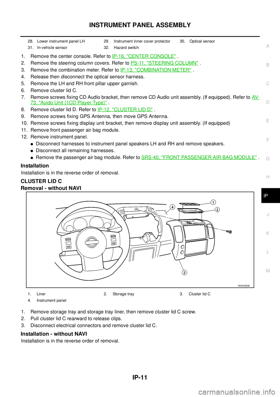
1. Remove the center console. Refer toIP-16, "CENTER CONSOLE".
2. Remove the steering column covers. Refer toPS-11, "
STEERING COLUMN".
3. Remove the combination meter. Refer toIP-13, "
COMBINATION METER".
4. Release then disconnect the optical sensor harness.
5. Remove the LH and RH front pillar upper garnish.
6. Remove cluster lid C.
7. Remove screws fixing CD Audio bracket, then remove CD Audio unit assembly. (If equipped). Refer toAV-
73, "Auido Unit (1CD Player Type)".
8. Remove cluster lid D. Refer toIP-12, "
CLUSTER LID D".
9. Remove screws fixing GPS Antenna, then move GPS Antenna.
10. Remove screws fixing display unit bracket, then remove display unit assembly. (If equipped)
11. Remove front passenger air bag module.
12. Remove instrument panel.
lDisconnect harnesses to instrument panel speakers LH and RH and remove speakers.
lDisconnect all remaining harnesses.
lRemove the passenger air bag module. Refer toSRS-40, "FRONT PASSENGER AIR BAG MODULE".
Installation
Installation is in the reverse order of removal.
CLUSTER LID C
Removal - without NAVI
1. Remove storage tray and storage tray liner, then remove cluster lid C screw.
2. Pull cluster lid C rearward to release clips.
3. Disconnect electrical connectors and remove cluster lid C.
Installation - without NAVI
Installation is in the reverse order of removal.
28. Lower instrument panel LH 29. Instrument inner cover protector 30. Optical sensor
31. In-vehicle sensor 32. Hazard switch
WIIA0563E
1. Liner 2. Storage tray 3. Cluster lid C
4. Instrument panel
Page 1778 of 3171
LAN-1
LAN SYSTEM
K ELECTRICAL
CONTENTS
C
D
E
F
G
H
I
J
L
M
SECTIONLAN
A
B
LAN
LAN SYSTEM
CAN
PRECAUTIONS .......................................................... 3
Precautions for Supplemental Restraint System
(SRS)“AIRBAG”and“SEATBELTPRE-TEN-
SIONER” .................................................................. 3
Precautions When Using CONSULT-II ..................... 3
CHECK POINTS FOR USING CONSULT-II ......... 3
Precautions For Trouble Diagnosis .......................... 3
CAN SYSTEM ....................................................... 3
Precautions For Harness Repair .............................. 3
CAN SYSTEM ....................................................... 3
TROUBLE DIAGNOSES WORK FLOW .................... 5
When Displaying CAN Communication System
Errors ....................................................................... 5
WHEN A MALFUNCTION IS DETECTED BY
CAN COMMUNICATION SYSTEM ....................... 5
WHEN A MALFUNCTION IS DETECTED
EXCEPT CAN COMMUNICATION SYSTEM ........ 5
TROUBLE DIAGNOSIS FLOW CHART ............... 6
Diagnosis Procedure ................................................ 7
SELECTING CAN SYSTEM TYPE (HOW TO
USE SPECIFICATION TABLE) ............................. 7
ACQUISITION OF DATA BY CONSULT-II ............ 8
HOW TO USE CHECK SHEET TABLE ................ 9
CAN Diagnostic Support Monitor ........................... 15
DESCRIPTION OF “CAN DIAG SUPPORT
MNTR” SCREEN FOR ECM ............................... 15
DESCRIPTION OF “CAN DIAG SUPPORT
MNTR” SCREEN FOR TCM ............................... 16
DESCRIPTION OF “CAN DIAG SUPPORT
MNTR” SCREEN FOR NAVI CONTROL UNIT ... 17
DESCRIPTION OF “CAN DIAG SUPPORT
MNTR” SCREEN FOR DIFFERENTIAL LOCK
CONTROL UNIT ................................................. 18
DESCRIPTION OF “CAN DIAG SUPPORT
MNTR” SCREEN FOR FRONT AIR CONTROL... 19
DESCRIPTION OF “CAN DIAG SUPPORT
MNTR” SCREEN FOR BCM ............................... 20
DESCRIPTION OF “CAN DIAG SUPPORT
MNTR” SCREEN FOR TRANSFER CONTROLUNIT .................................................................... 21
DESCRIPTION OF “CAN DIAG SUPPORT
MNTR” SCREEN FOR ABS ACTUATOR AND
ELECTRIC UNIT (CONTROL UNIT) ................... 21
DESCRIPTION OF “CAN DIAG SUPPORT
MNTR” SCREEN FOR IPDM E/R ....................... 22
CAN COMMUNICATION ........................................... 23
System Description ................................................. 23
Component Parts and Harness Connector Location... 23
LHD MODELS ..................................................... 23
RHD MODELS .................................................... 24
Schematic ............................................................... 25
Wiring Diagram — CAN — ..................................... 26
CAN Communication Unit ....................................... 30
TYPE 1/ TYPE 2/ TYPE 3 ................................... 32
TYPE 4/ TYPE 5 .................................................. 34
TYPE 6/ TYPE 7/ TYPE 8/ TYPE 9/ TYPE 10/
TYPE 11/ TYPE 16/ TYPE 17 .............................. 36
TYPE 12/ TYPE 13/ TYPE 14/ TYPE 15 ............. 40
CAN SYSTEM (TYPE 1) ........................................... 44
Component Parts and Harness Connector Location... 44
Schematic ............................................................... 44
Wiring Diagram — CAN — ..................................... 44
Check Sheet ........................................................... 45
CHECK SHEET RESULTS (EXAMPLE) ............. 47
CAN SYSTEM (TYPE 2) ........................................... 56
Component Parts and Harness Connector Location... 56
Schematic ............................................................... 56
Wiring Diagram — CAN — ..................................... 56
Check Sheet ........................................................... 57
CHECK SHEET RESULTS (EXAMPLE) ............. 59
CAN SYSTEM (TYPE 3) ........................................... 68
Component Parts and Harness Connector Location... 68
Schematic ............................................................... 68
Wiring Diagram — CAN — ..................................... 68
Check Sheet ........................................................... 69
CHECK SHEET RESULTS (EXAMPLE) ............. 71
CAN SYSTEM (TYPE 4) ........................................... 82
Component Parts and Harness Connector Location... 82
Schematic ............................................................... 82
Page 1780 of 3171
![NISSAN NAVARA 2005 Repair Workshop Manual PRECAUTIONS
LAN-3
[CAN]
C
D
E
F
G
H
I
J
L
MA
B
LAN
[CAN]PRECAUTIONSPFP:00001
Precautions for Supplemental Restraint System (SRS) “AIR BAG” and “SEAT
BELT PRE-TENSIONER”
EKS00Q9Y
The Supplement NISSAN NAVARA 2005 Repair Workshop Manual PRECAUTIONS
LAN-3
[CAN]
C
D
E
F
G
H
I
J
L
MA
B
LAN
[CAN]PRECAUTIONSPFP:00001
Precautions for Supplemental Restraint System (SRS) “AIR BAG” and “SEAT
BELT PRE-TENSIONER”
EKS00Q9Y
The Supplement](/manual-img/5/57362/w960_57362-1779.png)
PRECAUTIONS
LAN-3
[CAN]
C
D
E
F
G
H
I
J
L
MA
B
LAN
[CAN]PRECAUTIONSPFP:00001
Precautions for Supplemental Restraint System (SRS) “AIR BAG” and “SEAT
BELT PRE-TENSIONER”
EKS00Q9Y
The Supplemental Restraint System such as “AIR BAG” and “SEAT BELT PRE-TENSIONER”, used along
with a front seat belt, helps to reduce the risk or severity of injury to the driver and front passenger for certain
types of collision. Information necessary to service the system safely is included in the SRS and SB section of
this Service Manual.
WARNING:
lTo avoid rendering the SRS inoperative, which could increase the risk of personal injury or death
in the event of a collision which would result in air bag inflation, all maintenance must be per-
formed by an authorized NISSAN/INFINITI dealer.
lImproper maintenance, including incorrect removal and installation of the SRS, can lead to per-
sonal injury caused by unintentional activation of the system. For removal of Spiral Cable and Air
Bag Module, see the SRS section.
lDo not use electrical test equipment on any circuit related to the SRS unless instructed to in this
Service Manual. SRS wiring harnesses can be identified by yellow and/or orange harnesses or
harness connectors.
Precautions When Using CONSULT-IIEKS00LBE
When connecting CONSULT-II to data link connector, connect them through CONSULT-II CONVERTER.
CAUTION:
If CONSULT-II is used with no connection of CONSULT-II CONVERTER, malfunctions might be
detected in self-diagnosis depending on control unit which carry out CAN communication.
CHECK POINTS FOR USING CONSULT-II
1. Has CONSULT-II been used without connecting CONSULT-II CONVERTER on this vehicle?
–If YES, GO TO 2.
–If NO, GO TO 5.
2. Is there any indication other than indications relating to CAN communication system in the self-diagnosis
results?
–If YES, GO TO 3.
–If NO, GO TO 4.
3. Based on self-diagnosis results unrelated to CAN communication, carry out the inspection.
4. Malfunctions may be detected in self-diagnosis depending on control units carrying out CAN communica-
tion. Therefore, erase the self-diagnosis results.
5. Diagnose CAN communication system. Refer toLAN-5, "
TROUBLE DIAGNOSES WORK FLOW".
Precautions For Trouble DiagnosisEKS00LBF
CAN SYSTEM
lDo not apply voltage of 7.0 V or higher to the measurement terminals.
lUse the tester with its open terminal voltage being 7.0 V or less.
lBe sure to turn ignition switch off and disconnect negative battery terminal before checking the circuit.
Precautions For Harness RepairEKS00LBG
CAN SYSTEM
lSolder the repaired parts, and wrap with tape. [Frays of twisted
line must be within 110 mm (4.33 in).]
PKIA0306E
Page 2084 of 3171
LT-1
LIGHTING SYSTEM
K ELECTRICAL
CONTENTS
C
D
E
F
G
H
I
J
L
M
SECTIONLT
A
B
LT
LIGHTING SYSTEM
PRECAUTIONS .......................................................... 4
Precautions for Supplemental Restraint System
(SRS)“AIRBAG”and“SEATBELTPRE-TEN-
SIONER” .................................................................. 4
General Precautions for Service Operations ............ 4
Wiring Diagrams and Trouble Diagnosis .................. 4
HEADLAMP -CONVENTIONAL TYPE- ..................... 5
Component Parts and Harness Connector Location..... 5
System Description .................................................. 5
OUTLINE ............................................................... 5
FRIENDLY LIGHTING FUNCTION ....................... 6
CAN Communication System Description ................ 6
Schematic ................................................................ 7
Wiring Diagram - H/LAMP - ...................................... 8
Terminals and Reference Value for BCM ............... 12
Terminals and Reference Values for IPDM E/R ..... 12
How to Proceed With Trouble Diagnosis ................ 13
Preliminary Check .................................................. 13
CHECK POWER SUPPLY AND GROUND CIR-
CUIT .................................................................... 13
CONSULT-II Functions (BCM) ............................... 15
CONSULT-II BASIC OPERATION ....................... 15
WORK SUPPORT ............................................... 16
DATA MONITOR ................................................. 16
ACTIVE TEST ..................................................... 17
CONSULT-II Functions (IPDM E/R) ....................... 18
CONSULT-II BASIC OPERATION ....................... 18
DATA MONITOR ................................................. 19
ACTIVE TEST ..................................................... 19
Headlamp High Beam Does Not Illuminate (Both
Sides) ..................................................................... 20
Headlamp HI Beam Does Not Illuminate (One Side)... 22
High Beam Indicator Lamp Does Not Illuminate .... 23
Headlamp LO Beam Does Not Illuminate (Both
Sides) ..................................................................... 23
Headlamp LO Beam Does Not Illuminate (One Side)
... 25
Headlamps Do Not Turn OFF ................................ 26
Aiming Adjustment ................................................. 28
LOW BEAM AND HIGH BEAM ........................... 28Bulb Replacement .................................................. 29
HEADLAMP HIGH/LOW BEAM .......................... 29
FRONT TURN SIGNAL LAMP ............................ 29
CLEARANCE LAMP ............................................ 29
Removal and Installation ........................................ 30
REMOVAL ........................................................... 30
INSTALLATION ................................................... 30
Disassembly and Assembly .................................... 30
DISASSEMBLY ................................................... 30
HEADLAMP - DAYTIME LIGHT SYSTEM - ............. 31
Component Parts and Harness Connector Location... 31
System Description ................................................. 31
OUTLINE ............................................................. 32
DAYTIME LIGHT OPERATION ........................... 32
COMBINATION SWITCH READING FUNCTION... 33
AUTO LIGHT OPERATION ................................. 33
CAN Communication System Description .............. 33
CAN Communication Unit ....................................... 33
Schematic ............................................................... 34
Wiring Diagram — DTRL — ................................... 35
Terminals and Reference Values for BCM .............. 39
Terminals and Reference Values for IPDM E/R ...... 39
How to Proceed With Trouble Diagnosis ................ 40
Preliminary Check .................................................. 40
CHECK POWER SUPPLY AND GROUND CIR-
CUIT .................................................................... 40
CONSULT-II Functions (BCM) ................................ 42
CONSULT-II BASIC OPERATION ....................... 42
DATA MONITOR ................................................. 43
ACTIVE TEST ..................................................... 44
CONSULT-II Functions (IPDM E/R) ........................ 45
CONSULT-II BASIC OPERATION ....................... 45
DATA MONITOR ................................................. 46
ACTIVE TEST ..................................................... 46
Daytime Light Control Does Not Operate Properly
(Normal Headlamps Operate Properly) .................. 47
Aiming Adjustment .................................................. 48
Bulb Replacement .................................................. 48
Removal and Installation ........................................ 48
Disassembly and Assembly .................................... 48
Page 2087 of 3171
LT-4
PRECAUTIONS
PRECAUTIONS
PFP:00011
Precautions for Supplemental Restraint System (SRS) “AIR BAG” and “SEAT
BELT PRE-TENSIONER”
EKS00N1L
The Supplemental Restraint System such as “AIR BAG” and “SEAT BELT PRE-TENSIONER”, used along
with a front seat belt, helps to reduce the risk or severity of injury to the driver and front passenger for certain
types of collision. Information necessary to service the system safely is included in the SRS and SB section of
this Service Manual.
WARNING:
lTo avoid rendering the SRS inoperative, which could increase the risk of personal injury or death
in the event of a collision which would result in air bag inflation, all maintenance must be per-
formed by an authorized NISSAN/INFINITI dealer.
lImproper maintenance, including incorrect removal and installation of the SRS, can lead to per-
sonal injury caused by unintentional activation of the system. For removal of Spiral Cable and Air
Bag Module, see the SRS section.
lDo not use electrical test equipment on any circuit related to the SRS unless instructed to in this
Service Manual. SRS wiring harnesses can be identified by yellow and/or orange harnesses or
harness connectors.
General Precautions for Service OperationsEKS00L4H
lNever work with wet hands.
lTurn the lighting switch OFF before disconnecting and connecting the connector.
lWhen checking the headlamp on/off operation, check it on vehicle and with the power connected to the
vehicle-side connector.
lDo not touch the headlamp bulb glass surface with bare hands or allow oil or grease to get on it. Do not
touch the headlamp bulb just after the headlamp is turned off, because it is very hot.
lWhen the bulb has burned out, wrap it in a thick vinyl bag and discard. Do not break the bulb.
lLeaving the bulb removed from the headlamp housing for a long period of time can deteriorate the perfor-
mance of the lens and reflector (dirt, clouding). Always prepare a new bulb and have it on hand when
replacing the bulb.
lDo not use organic solvent (paint thinner or gasoline) to clean lamps and to remove old sealant.
Wiring Diagrams and Trouble DiagnosisEKS00L4I
When you read wiring diagrams, refer to the following:
lRefer toGI-15, "How to Read Wiring Diagrams".
lRefer toPG-4, "POWER SUPPLY ROUTING CIRCUIT".
When you perform trouble diagnosis, refer to the following:
lRefer toGI-11, "HOW TO FOLLOW TEST GROUPS IN TROUBLE DIAGNOSES".
lRefer toGI-24, "How to Perform Efficient Diagnosis for an Electrical Incident".
Page 2276 of 3171
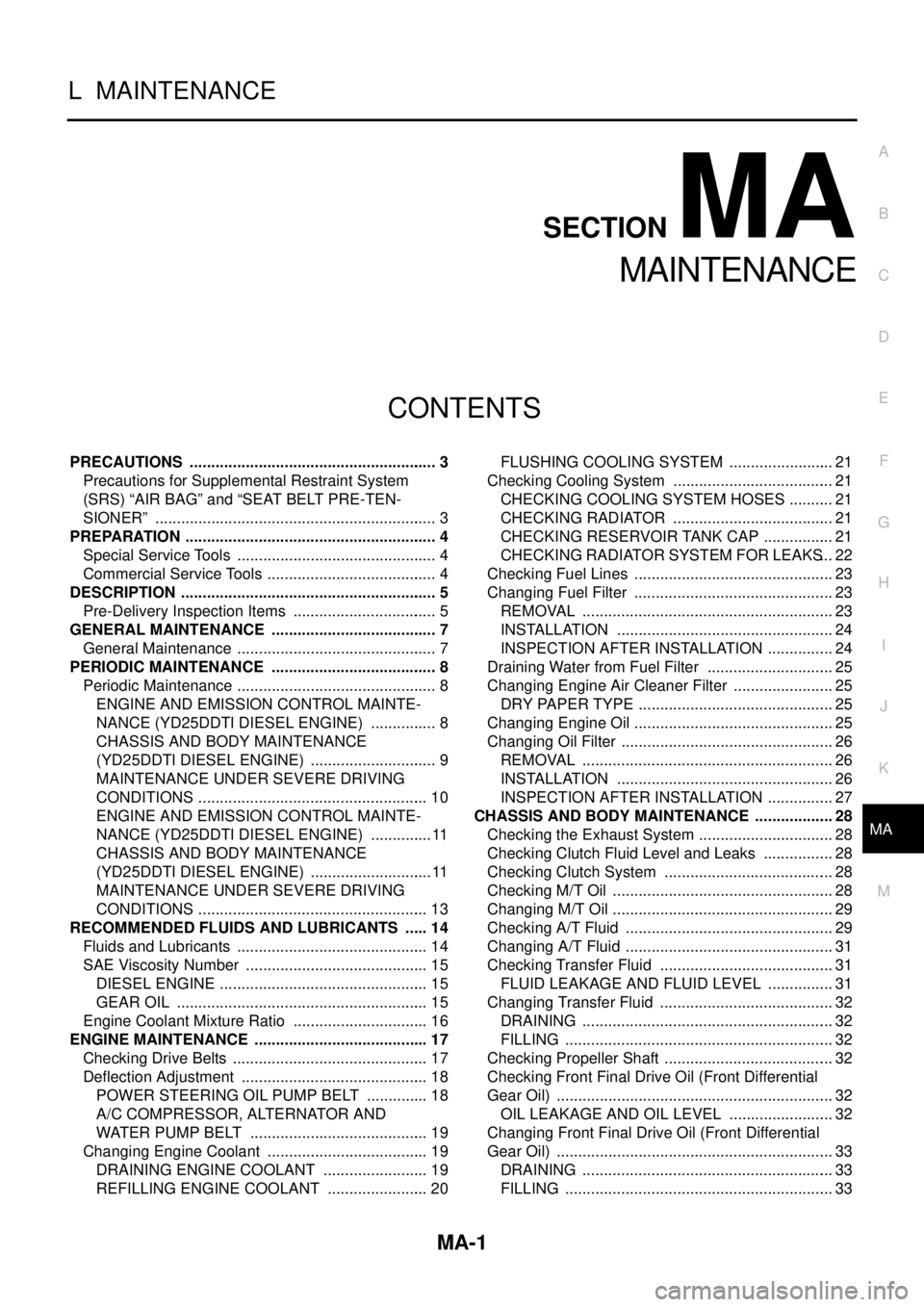
MA-1
MAINTENANCE
L MAINTENANCE
CONTENTS
C
D
E
F
G
H
I
J
K
M
SECTIONMA
A
B
MA
MAINTENANCE
PRECAUTIONS .......................................................... 3
Precautions for Supplemental Restraint System
(SRS)“AIRBAG”and“SEATBELTPRE-TEN-
SIONER” .................................................................. 3
PREPARATION ........................................................... 4
Special Service Tools ............................................... 4
Commercial Service Tools ........................................ 4
DESCRIPTION ............................................................ 5
Pre-Delivery Inspection Items .................................. 5
GENERAL MAINTENANCE ....................................... 7
General Maintenance ............................................... 7
PERIODIC MAINTENANCE ....................................... 8
Periodic Maintenance ............................................... 8
ENGINE AND EMISSION CONTROL MAINTE-
NANCE (YD25DDTI DIESEL ENGINE) ................ 8
CHASSIS AND BODY MAINTENANCE
(YD25DDTI DIESEL ENGINE) .............................. 9
MAINTENANCE UNDER SEVERE DRIVING
CONDITIONS ...................................................... 10
ENGINE AND EMISSION CONTROL MAINTE-
NANCE (YD25DDTI DIESEL ENGINE) ............... 11
CHASSIS AND BODY MAINTENANCE
(YD25DDTI DIESEL ENGINE) ............................. 11
MAINTENANCE UNDER SEVERE DRIVING
CONDITIONS ...................................................... 13
RECOMMENDED FLUIDS AND LUBRICANTS ...... 14
Fluids and Lubricants ............................................. 14
SAE Viscosity Number ........................................... 15
DIESEL ENGINE ................................................. 15
GEAR OIL ........................................................... 15
Engine Coolant Mixture Ratio ................................ 16
ENGINE MAINTENANCE ......................................... 17
Checking Drive Belts .............................................. 17
Deflection Adjustment ............................................ 18
POWER STEERING OIL PUMP BELT ............... 18
A/C COMPRESSOR, ALTERNATOR AND
WATER PUMP BELT .......................................... 19
Changing Engine Coolant ...................................... 19
DRAINING ENGINE COOLANT ......................... 19
REFILLING ENGINE COOLANT ........................ 20FLUSHING COOLING SYSTEM ......................... 21
Checking Cooling System ...................................... 21
CHECKING COOLING SYSTEM HOSES ........... 21
CHECKING RADIATOR ...................................... 21
CHECKING RESERVOIR TANK CAP ................. 21
CHECKING RADIATOR SYSTEM FOR LEAKS... 22
Checking Fuel Lines ............................................... 23
Changing Fuel Filter ............................................... 23
REMOVAL ........................................................... 23
INSTALLATION ................................................... 24
INSPECTION AFTER INSTALLATION ................ 24
Draining Water from Fuel Filter .............................. 25
Changing Engine Air Cleaner Filter ........................ 25
DRY PAPER TYPE .............................................. 25
Changing Engine Oil ............................................... 25
Changing Oil Filter .................................................. 26
REMOVAL ........................................................... 26
INSTALLATION ................................................... 26
INSPECTION AFTER INSTALLATION ................ 27
CHASSIS AND BODY MAINTENANCE ................... 28
Checking the Exhaust System ................................ 28
Checking Clutch Fluid Level and Leaks ................. 28
Checking Clutch System ........................................ 28
Checking M/T Oil .................................................... 28
Changing M/T Oil .................................................... 29
Checking A/T Fluid ................................................. 29
Changing A/T Fluid ................................................. 31
Checking Transfer Fluid ......................................... 31
FLUID LEAKAGE AND FLUID LEVEL ................ 31
Changing Transfer Fluid ......................................... 32
DRAINING ........................................................... 32
FILLING ............................................................... 32
Checking Propeller Shaft ........................................ 32
Checking Front Final Drive Oil (Front Differential
Gear Oil) ................................................................. 32
OIL LEAKAGE AND OIL LEVEL ......................... 32
Changing Front Final Drive Oil (Front Differential
Gear Oil) ................................................................. 33
DRAINING ........................................................... 33
FILLING ............................................................... 33
Page 2278 of 3171
PRECAUTIONS
MA-3
C
D
E
F
G
H
I
J
K
MA
B
MA
PRECAUTIONSPFP:00001
Precautions for Supplemental Restraint System (SRS) “AIR BAG” and “SEAT
BELT PRE-TENSIONER”
ELS001HP
The Supplemental Restraint System such as “AIR BAG” and “SEAT BELT PRE-TENSIONER”, used along
with a front seat belt, helps to reduce the risk or severity of injury to the driver and front passenger for certain
types of collision. Information necessary to service the system safely is included in the SRS and SB section of
this Service Manual.
WARNING:
lTo avoid rendering the SRS inoperative, which could increase the risk of personal injury or death
in the event of a collision which would result in air bag inflation, all maintenance must be per-
formed by an authorized NISSAN/INFINITI dealer.
lImproper maintenance, including incorrect removal and installation of the SRS, can lead to per-
sonal injury caused by unintentional activation of the system. For removal of Spiral Cable and Air
Bag Module, see the SRS section.
lDo not use electrical test equipment on any circuit related to the SRS unless instructed to in this
Service Manual. SRS wiring harnesses can be identified by yellow and/or orange harnesses or
harness connectors.