2005 NISSAN NAVARA SRS
[x] Cancel search: SRSPage 2629 of 3171
PS-2
PRECAUTIONS
PRECAUTIONS
PFP:00001
Precautions for Supplemental Restraint System (SRS) “AIR BAG” and “SEAT
BELT PRE-TENSIONER”
EGS001M0
The Supplemental Restraint System such as “AIR BAG” and “SEAT BELT PRE-TENSIONER”, used along
with a front seat belt, helps to reduce the risk or severity of injury to the driver and front passenger for certain
types of collision. Information necessary to service the system safely is included in the SRS and SB section of
this Service Manual.
WARNING:
lTo avoid rendering the SRS inoperative, which could increase the risk of personal injury or death
in the event of a collision which would result in air bag inflation, all maintenance must be per-
formed by an authorized NISSAN/INFINITI dealer.
lImproper maintenance, including incorrect removal and installation of the SRS, can lead to per-
sonal injury caused by unintentional activation of the system. For removal of Spiral Cable and Air
Bag Module, see the SRS section.
lDo not use electrical test equipment on any circuit related to the SRS unless instructed to in this
Service Manual. SRS wiring harnesses can be identified by yellow and/or orange harnesses or
harness connectors.
Precautions for Steering SystemEGS001L9
lIn case of removing steering gear assembly, make the final tightening with grounded and unloaded vehi-
cle condition, and then check wheel alignment.
lObserve the following precautions when disassembling.
–Before disassembly, thoroughly clean the outside of the unit.
–Disassembly should be done in a clean work area. It is important to prevent the internal parts from becom-
ing contaminated by dirt or other foreign matter.
–For easier and proper assembly, place disassembled parts in order on a parts rack.
–Use nylon cloth or paper towels to clean the parts; common shop rags can leave lint that might interfere
with their operation.
–Do not reuse non-reusable parts.
–Before assembling, apply the specified grease to the directed parts.
Page 2637 of 3171
PS-10
STEERING WHEEL
Removal and Installation
EGS001LH
REMOVAL
NOTE:
When reconnecting spiral cable, fix cable with a tape so that fixing case and rotating part keep aligned. This
will omit neutral position alignment procedure during spiral installation.
1. Set vehicle to the straight-ahead position.
2. Remove driver air bag module. Refer toSRS-36, "
DRIVER AIR BAG MODULE".
3. Remove steering wheel lock nut after steering is locked.
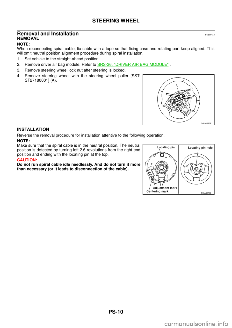
4. Remove steering wheel with the steering wheel puller [SST:
ST27180001] (A).
INSTALLATION
Reverse the removal procedure for installation attentive to the following operation.
NOTE:
Make sure that the spiral cable is in the neutral position. The neutral
position is detected by turning left 2.6 revolutions from the right end
position and ending with the locating pin at the top.
CAUTION:
Do not run spiral cable idle needlessly. And do not turn it more
than necessary (or it leads to disconnection of the cable).
SGIA1323E
PHIA0275E
Page 2638 of 3171
STEERING COLUMN
PS-11
C
D
E
F
H
I
J
K
L
MA
B
PS
STEERING COLUMNPFP:48810
Removal and InstallationEGS001LI
COMPONENT
CAUTION:
lDo not give axial impact to steering column assembly during removal and installation.
lDo not move steering gear assembly when removing steering column assembly.
REMOVAL
1. Set vehicle to the straight ahead-position.
2. Remove driver air bag module. Refer toSRS-36, "
DRIVER AIR BAG MODULE".
3. Remove steering wheel. Refer toPS-10, "
Removal and Installation".
4. Remove steering column cover (upper and lower). Refer toIP-10, "
INSTRUMENT PANEL ASSEMBLY".
5. Remove combination switch & spiral cable. Refer toSRS-38, "
SPIRAL CABLE".
6. Remove lower instrument panel LH. Refer toIP-10, "
INSTRUMENT PANEL ASSEMBLY".
7. Disconnect each switch connectors installed to steering column assembly, and then disconnect harness
from steering column assembly.
8. Remove fixing bolt of upper joint (steering column assembly side), and then remove upper joint from
steering column assembly.
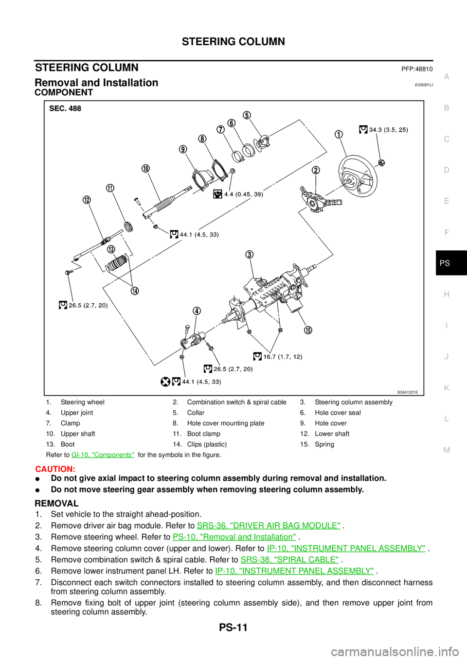
1. Steering wheel 2. Combination switch & spiral cable 3. Steering column assembly
4. Upper joint 5. Collar 6. Hole cover seal
7. Clamp 8. Hole cover mounting plate 9. Hole cover
10. Upper shaft 11. Boot clamp 12. Lower shaft
13. Boot 14. Clips (plastic) 15. Spring
Refer toGI-10, "
Components"for the symbols in the figure.
SGIA1221E
Page 2678 of 3171
RF-1
ROOF
IBODY
CONTENTS
C
D
E
F
G
H
J
K
L
M
SECTIONRF
A
B
RF
ROOF
PRECAUTIONS .......................................................... 2
Precautions for Supplemental Restraint System
(SRS)“AIRBAG”and“SEATBELTPRE-TEN-
SIONER” .................................................................. 2
Precautions .............................................................. 2
PREPARATION ........................................................... 3
Commercial Service Tool ......................................... 3
SQUEAK AND RATTLE TROUBLE DIAGNOSES..... 4
Work Flow ................................................................ 4
CUSTOMER INTERVIEW ..................................... 4
DUPLICATE THE NOISE AND TEST DRIVE ....... 5
CHECK RELATED SERVICE BULLETINS ........... 5
LOCATE THE NOISE AND IDENTIFY THE
ROOT CAUSE ...................................................... 5
REPAIR THE CAUSE ........................................... 5
CONFIRM THE REPAIR ....................................... 6
Generic Squeak and Rattle Troubleshooting ........... 6
INSTRUMENT PANEL .......................................... 6
CENTER CONSOLE ............................................. 6
DOORS ................................................................. 6
TRUNK .................................................................. 7
SUNROOF/HEADLINING ..................................... 7
SEATS ................................................................... 7
UNDERHOOD ....................................................... 7
Diagnostic Worksheet .............................................. 8
SUNROOF ................................................................ 10
Component Parts and Harness Connector Location... 10
System Description ................................................. 11
TILT UP / SLIDE CLOSE OPERATION ................ 11
TILT DOWN / SLIDE OPEN OPERATION ........... 11AUTO OPERATION ............................................. 11
ANTI-PINCH FUNCTION .................................... 11
MEMORY RESET PROCEDURE ....................... 12
INITIALIZATION PROCEDURE .......................... 12
CAN Communication System Description .............. 13
CAN Communication Unit ....................................... 13
Wiring Diagram — SROOF — ................................ 14
Terminals and Reference Value for BCM ............... 15
Terminals and Reference Value for Sunroof Motor
Assembly ................................................................ 15
Work Flow ............................................................... 16
Trouble Diagnosis Symptom Chart ......................... 16
BCM Power Supply and Ground Circuit Check ...... 16
Sunroof Motor Assembly Power Supply and Ground
Circuit Check .......................................................... 17
Sunroof Switch System Check ............................... 18
Fitting Adjustment ................................................... 20
GAP ADJUSTMENT ............................................ 20
HEIGHT DIFFERENCE ADJUSTMENT .............. 20
Removal and Installation ........................................ 21
SUNROOF UNIT ................................................. 22
GLASS LID .......................................................... 22
WIND DEFLECTOR ............................................ 23
SUNSHADE ........................................................ 23
SUNROOF MOTOR ............................................ 23
DRAIN HOSES .................................................... 25
WEATHERSTRIP ................................................ 25
REAR DRAIN ASSEMBLY .................................. 25
LINK AND WIRE ASSEMBLY ............................. 26
Page 2679 of 3171
RF-2
PRECAUTIONS
PRECAUTIONS
PFP:00001
Precautions for Supplemental Restraint System (SRS) “AIR BAG” and “SEAT
BELT PRE-TENSIONER”
EIS00CE9
The Supplemental Restraint System such as “AIR BAG” and “SEAT BELT PRE-TENSIONER”, used along
with a front seat belt, helps to reduce the risk or severity of injury to the driver and front passenger for certain
types of collision. Information necessary to service the system safely is included in the SRS and SB section of
this Service Manual.
WARNING:
lTo avoid rendering the SRS inoperative, which could increase the risk of personal injury or death
in the event of a collision which would result in air bag inflation, all maintenance must be per-
formed by an authorized NISSAN/INFINITI dealer.
lImproper maintenance, including incorrect removal and installation of the SRS, can lead to per-
sonal injury caused by unintentional activation of the system. For removal of Spiral Cable and Air
Bag Module, see the SRS section.
lDo not use electrical test equipment on any circuit related to the SRS unless instructed to in this
Service Manual. SRS wiring harnesses can be identified by yellow and/or orange harnesses or
harness connectors.
PrecautionsEIS00B92
lDisconnect both battery cables in advance.
lNever tamper with or force air bag lid open, as this may adversely affect air bag performance.
lBe careful not to scratch pad and other parts.
lWhen removing or disassembling any part, be careful not to damage or deform it. Protect parts which may
get in the way with cloth.
lWhen removing parts with a screwdriver or other tool, protect parts by wrapping them with vinyl or tape.
lKeep removed parts protected with cloth.
lIf a clip is deformed or damaged, replace it.
lIf an unreusable part is removed, replace it with a new one.
lTighten bolts and nuts firmly to the specified torque.
lAfter re-assembly has been completed, make sure each part functions correctly.
lRemove stains in the following way.
Water-soluble stains:
Dip a soft cloth in warm water, and then squeeze it tightly. After wiping the stain, wipe with a soft dry cloth.
Oil stain:
Dissolve a synthetic detergent in warm water (density of 2 to 3% or less), dip the cloth, then clean off the stain
with the cloth. Next, dip the cloth in fresh water and squeeze it tightly. Then clean off the detergent completely.
Thenwipetheareawithasoftdrycloth.
lDo not use any organic solvent, such as thinner or benzine.
Page 2704 of 3171
RFD-1
REAR FINAL DRIVE
D DRIVELINE/AXLE
CONTENTS
C
E
F
G
H
I
J
K
L
M
SECTIONRFD
A
B
RFD
REAR FINAL DRIVE
WITH LIMITED SLIP DIFFERENTIAL
PRECAUTIONS .......................................................... 3
Limited Slip Differential (LSD) Performance Judge-
ment ......................................................................... 3
METHOD FOR TROUBLESHOOTING ................. 3
Service Notice or Precautions .................................. 3
PREPARATION ........................................................... 4
Special Service Tools ............................................... 4
Commercial Service Tools ........................................ 5
NOISE, VIBRATION, AND HARSHNESS (NVH)
TROUBLESHOOTING ................................................ 7
NVH Troubleshooting Chart ..................................... 7
DESCRIPTION ............................................................ 8
Cross-Sectional View ............................................... 8
DIFFERENTIAL GEAR OIL ........................................ 9
Changing Differential Gear Oil ................................. 9
DRAINING ............................................................. 9
FILLING ................................................................. 9
Checking Differential Gear Oil .................................. 9
OIL LEAKAGE AND OIL LEVEL ........................... 9
FRONT OIL SEAL .................................................... 10
Removal and Installation ........................................ 10
REMOVAL ........................................................... 10
INSTALLATION .................................................... 11
CARRIER COVER .................................................... 13
Removal and Installation ........................................ 13
REMOVAL ........................................................... 13
INSTALLATION ................................................... 13
REAR FINAL DRIVE ASSEMBLY ............................ 14
Removal and Installation ........................................ 14
REMOVAL ........................................................... 14
INSTALLATION ................................................... 14
Disassembly and Assembly ................................... 15
COMPONENTS .................................................. 15
ASSEMBLY INSPECTION AND ADJUSTMENT... 16
DISASSEMBLY ................................................... 19
INSPECTION AFTER DISASSEMBLY ............... 22
SELECTION ADJUSTING WASHERS ............... 23
ASSEMBLY ......................................................... 24SERVICE DATA AND SPECIFICATIONS (SDS) ...... 31
General Specifications ............................................ 31
Inspection and Adjustment ..................................... 31
PRELOAD TORQUE ........................................... 31
BACKLASH ......................................................... 31
COMPANION FLANGE RUNOUT ....................... 31
SELECTIVE PARTS ............................................ 32
WITH ELECTRONIC LOCKING DIFFEREN-
TIAL
PRECAUTIONS ........................................................ 33
Precautions for Supplemental Restraint System
(SRS)“AIRBAG”and“SEATBELTPRE-TEN-
SIONER” ................................................................. 33
Precautions for Differential Case Assembly and Dif-
ferential Lock Control Unit Replacement ................ 33
CHECK DIFF LOCK INDICATOR LAMP ............. 33
METHOD FOR ADJUSTMENT ........................... 34
Precautions ............................................................. 34
Service Notice or Precaution .................................. 35
Wiring Diagrams and Trouble Diagnosis ................ 35
PREPARATION ......................................................... 36
Special Service Tools ............................................. 36
Commercial Service Tools ...................................... 37
NOISE, VIBRATION AND HARSHNESS (NVH)
TROUBLESHOOTING .............................................. 39
NVH Troubleshooting Chart ................................... 39
DIFFERENTIAL GEAR OIL ...................................... 40
Changing Differential Gear Oil ................................ 40
DRAINING ........................................................... 40
FILLING ............................................................... 40
Checking Differential Gear Oil ................................ 40
OIL LEAKAGE AND OIL LEVEL ......................... 40
DIFFERENTIAL LOCK SYSTEM .............................. 41
Cross-sectional View .............................................. 41
Differential Lock Operation ..................................... 42
System Description ................................................. 42
DIFFERENTIAL LOCK SOLENOID .................... 42
DIFFERENTIAL LOCK POSITION SWITCH ....... 42
Page 2736 of 3171
![NISSAN NAVARA 2005 Repair Workshop Manual PRECAUTIONS
RFD-33
[WITH ELECTRONIC LOCKING DIFFERENTIAL]
C
E
F
G
H
I
J
K
L
MA
B
RFD
[WITH ELECTRONIC LOCKING DIFFERENTIAL]PRECAUTIONSPFP:00001
Precautions for Supplemental Restraint System (SRS) “A NISSAN NAVARA 2005 Repair Workshop Manual PRECAUTIONS
RFD-33
[WITH ELECTRONIC LOCKING DIFFERENTIAL]
C
E
F
G
H
I
J
K
L
MA
B
RFD
[WITH ELECTRONIC LOCKING DIFFERENTIAL]PRECAUTIONSPFP:00001
Precautions for Supplemental Restraint System (SRS) “A](/manual-img/5/57362/w960_57362-2735.png)
PRECAUTIONS
RFD-33
[WITH ELECTRONIC LOCKING DIFFERENTIAL]
C
E
F
G
H
I
J
K
L
MA
B
RFD
[WITH ELECTRONIC LOCKING DIFFERENTIAL]PRECAUTIONSPFP:00001
Precautions for Supplemental Restraint System (SRS) “AIR BAG” and “SEAT
BELT PRE-TENSIONER”
EDS003IE
The Supplemental Restraint System such as “AIR BAG” and “SEAT BELT PRE-TENSIONER”, used along
with a front seat belt, helps to reduce the risk or severity of injury to the driver and front passenger for certain
types of collision. Information necessary to service the system safely is included in the SRS and SB section of
this Service Manual.
WARNING:
lTo avoid rendering the SRS inoperative, which could increase the risk of personal injury or death
in the event of a collision which would result in air bag inflation, all maintenance must be per-
formed by an authorized NISSAN/INFINITI dealer.
lImproper maintenance, including incorrect removal and installation of the SRS, can lead to per-
sonal injury caused by unintentional activation of the system. For removal of Spiral Cable and Air
Bag Module, see the SRS section.
lDo not use electrical test equipment on any circuit related to the SRS unless instructed to in this
Service Manual. SRS wiring harnesses can be identified by yellow and/or orange harnesses or
harness connectors.
Precautions for Differential Case Assembly and Differential Lock Control Unit
Replacement
EDS003AG
lWhen replacing differential case assembly or differential lock control unit, check the DIFF LOCK indicator
pattern and adjustment of the position between differential case assembly and differential lock control unit
if necessary.
CHECK DIFF LOCK INDICATOR LAMP
1. Start engine. Run engine for at least 10 seconds.
2. Turn 4WD shift switch to “4LO” and confirm 4LO indicator lamp is turned on. Refer toTF-16, "
4WD SHIFT
SWITCH AND INDICATOR LAMP".
3. Stop vehicle and turn differential lock mode switch to “ON”.
4. Drive vehicle at 7 km/h (4 MPH) or less.
NOTE:
Differential case assembly must be given a rotation from rear left wheel and rear right wheel.
5. Check if DIFF LOCK indicator lamp flashes to turn on.
6. Check if DIFF LOCK indicator lamp and 4LO indicator lamp are changed properly as follows.
lIf each indication and state is OK, rear final drive assembly and differential lock control unit is working cor-
rectly.
lIf each indication and state is NG, rear final drive assembly and differential lock control unit is not working
correctly. Refer toRFD-34, "
METHOD FOR ADJUSTMENT".
Differential lock mode
switch4LO indicator lamp Vehicle speed (VSS)Differential case assem-
bly stateDIFF LOCK indicator
lamp
ONOFF7 km/h (4 MPH) < VSS
Disengage Flash VSS£7km/h(4MPH)
ON7 km/h (4 MPH) < VSS
VSS£7 km/h (4 MPH) Disengage®Engage Flash®ON
OFFOFF7 km/h (4 MPH) < VSS
Disengage OFF VSS£7km/h(4MPH)
ON7 km/h (4 MPH) < VSS
VSS£7km/h(4MPH)
Page 2818 of 3171
SB-1
SEAT BELTS
H RESTRAINTS
CONTENTS
C
D
E
F
G
I
J
K
L
M
SECTIONSB
A
B
SB
SEAT BELTS
PRECAUTIONS .......................................................... 2
Precautions for Supplemental Restraint System
(SRS)“AIRBAG”and“SEATBELTPRE-TEN-
SIONER” .................................................................. 2
Precautions for Seat Belt Service ............................ 2
AFTER A COLLISION ........................................... 2
SEAT BELTS .............................................................. 3
Removal and Installation of Front Seat Belt - King
Cab ........................................................................... 3
REMOVAL OF SEAT BELT RETRACTOR ............ 4
INSTALLATION OF SEAT BELT RETRACTOR..... 4
REMOVAL OF SEAT BELT BUCKLE .................... 4
INSTALLATION OF SEAT BELT BUCKLE ............ 4
Removal and Installation of Front Seat Belt - Double
Cab ........................................................................... 5
REMOVAL OF SEAT BELT RETRACTOR ............ 6
INSTALLATION OF SEAT BELT RETRACTOR..... 6
REMOVAL OF SEAT BELT BUCKLE .................... 6
INSTALLATION OF SEAT BELT BUCKLE ............ 6
Removal and Installation of Rear Seat Belt - King
Cab ........................................................................... 7
REMOVAL ............................................................. 8
INSTALLATION ..................................................... 8
REMOVAL OF SEAT BELT BUCKLE .................... 8
INSTALLATION OF SEAT BELT BUCKLE ............ 8
Removal and Installation of Rear Seat Belt - DoubleCab ........................................................................... 9
REMOVAL OF SEAT BELT RETRACTOR - OUT-
BOARD ................................................................ 10
INSTALLATION OF SEAT BELT RETRACTOR -
OUTBOARD ........................................................ 10
REMOVALOFSEATBELTRETRACTOR-CEN-
TER ..................................................................... 10
INSTALLATION OF SEAT BELT RETRACTOR -
CENTER .............................................................. 10
REMOVAL OF SEAT BELT BUCKLE .................. 10
INSTALLATION OF SEAT BELT BUCKLE .......... 10
Seat Belt Inspection ................................................ 11
AFTER A COLLISION ......................................... 11
PRELIMINARY CHECKS .................................... 11
SEAT BELT RETRACTOR ON-VEHICLE
CHECK ................................................................ 12
SEAT BELT RETRACTOR OFF-VEHICLE
CHECK ................................................................ 12
SEAT BELT WARNING SYSTEM ............................. 14
Description .............................................................. 14
LATCH (LOWER ANCHORS AND TETHER FOR
CHILDREN) SYSTEM ............................................... 15
Removal and Installation - Double Cab .................. 15
TOP TETHER STRAP CHILD RESTRAINT ............. 16
Removal and Installation - Double Cab .................. 16