2005 NISSAN NAVARA control unit
[x] Cancel search: control unitPage 2779 of 3171
![NISSAN NAVARA 2005 Repair Workshop Manual RFD-76
[WITH ELECTRONIC LOCKING DIFFERENTIAL]
DIFFERENTIAL LOCK CONTROL UNIT
DIFFERENTIAL LOCK CONTROL UNIT
PFP:28496
Removal and InstallationEDS003BC
REMOVAL
1. Turn the ignition switch OFF and disco NISSAN NAVARA 2005 Repair Workshop Manual RFD-76
[WITH ELECTRONIC LOCKING DIFFERENTIAL]
DIFFERENTIAL LOCK CONTROL UNIT
DIFFERENTIAL LOCK CONTROL UNIT
PFP:28496
Removal and InstallationEDS003BC
REMOVAL
1. Turn the ignition switch OFF and disco](/manual-img/5/57362/w960_57362-2778.png)
RFD-76
[WITH ELECTRONIC LOCKING DIFFERENTIAL]
DIFFERENTIAL LOCK CONTROL UNIT
DIFFERENTIAL LOCK CONTROL UNIT
PFP:28496
Removal and InstallationEDS003BC
REMOVAL
1. Turn the ignition switch OFF and disconnect the battery cables.
2. Remove the lower instrument panel LH (LHD models) or lower instrument panel RH (RHD models). Refer
toIP-13, "
LOWER INSTRUMENT PANEL LH"(LHD models) orIP-13, "LOWER INSTRUMENT PANEL
LH"(RHD models).
3. Disconnect the differential lock control unit connector.
4. Remove the two bolts and remove the differential lock control
unit.
INSTALLATION
Installation is in the reverse order of removal.
lWhen installing differential lock control unit, tighten bolts to the specified torque.
lAfter the installation, check DIFF LOCK indicator lamp. Refer toRFD-33, "Precautions for Differential
Case Assembly and Differential Lock Control Unit Replacement".
WDIA0254E
Differential lock control unit bolts : 5.1 N·m (0.52 kg-m, 45 in-lb)
Page 2784 of 3171
![NISSAN NAVARA 2005 Repair Workshop Manual REAR FINAL DRIVE ASSEMBLY
RFD-81
[WITH ELECTRONIC LOCKING DIFFERENTIAL]
C
E
F
G
H
I
J
K
L
MA
B
RFD
REAR FINAL DRIVE ASSEMBLYPFP:38300
Removal and InstallationEDS003BF
REMOVAL
1. Remove the rear propel NISSAN NAVARA 2005 Repair Workshop Manual REAR FINAL DRIVE ASSEMBLY
RFD-81
[WITH ELECTRONIC LOCKING DIFFERENTIAL]
C
E
F
G
H
I
J
K
L
MA
B
RFD
REAR FINAL DRIVE ASSEMBLYPFP:38300
Removal and InstallationEDS003BF
REMOVAL
1. Remove the rear propel](/manual-img/5/57362/w960_57362-2783.png)
REAR FINAL DRIVE ASSEMBLY
RFD-81
[WITH ELECTRONIC LOCKING DIFFERENTIAL]
C
E
F
G
H
I
J
K
L
MA
B
RFD
REAR FINAL DRIVE ASSEMBLYPFP:38300
Removal and InstallationEDS003BF
REMOVAL
1. Remove the rear propeller shaft. Refer toPR-8, "Removal and Installation".
lPlug rear end of transmission or transfer.
2. Remove the axle shafts and back plate and torque members. Refer toRAX-7, "
Removal and Installation".
3. Disconnect the following components from the rear final drive.
lABS sensor wire harness
lRear cable (LH) and rear cable (RH)
lBrake hoses and brake tube
lDifferential lock position switch harness connector
lDifferential lock solenoid harness connector
CAUTION:
Position the wire harness, cable and hoses away from the final drive assembly. Failure to do so
may result in components being damaged during rear axle assembly removal.
4. Support the rear final drive using a suitable jack.
5. Remove rear shock absorber lower bolts. Refer toRSU-6, "
Removal and Installation".
6. Remove leaf spring U-bolt nuts. Refer toRSU-7, "
Removal and Installation".
WARNING:
Support the rear final drive assembly using suitable jack before removing leaf spring U-bolt nuts.
7. Remove rear final drive assembly using suitable jack.
INSTALLATION
Installation is the reverse order of removal.
lWhen oil leaks while removing rear final drive assembly, check oil level after the installation. Refer to
RFD-40, "
Checking Differential Gear Oil".
lRefill brake fluid and bleed the air from the brake system. Refer toBR-11, "Bleeding Brake System".
lAfter the installation, check DIFF LOCK indicator lamp. Refer toRFD-33, "Precautions for Differential
Case Assembly and Differential Lock Control Unit Replacement".
Page 2877 of 3171

SE-6
SQUEAK AND RATTLE TROUBLE DIAGNOSES
FELT CLOTHTAPE
Used to insulate where movement does not occur. Ideal for instrument panel applications.
68370-4B000: 15´25 mm (0.59´0.98 in) pad/68239-13E00: 5 mm (0.20 in) wide tape roll
The following materials, not available through NISSAN Parts Department, can also be used to repair squeaks
and rattles.
UHMW(TEFLON) TAPE
Insulates where slight movement is present. Ideal for instrument panel applications.
SILICONE GREASE
Used in place of UHMW tape that will be visible or not fit.
Note: Will only last a few months.
SILICONE SPRAY
Use when grease cannot be applied.
DUCT TAPE
Use to eliminate movement.
CONFIRM THE REPAIR
Confirm that the cause of a noise is repaired by test driving the vehicle. Operate the vehicle under the same
conditions as when the noise originally occurred. Refer to the notes on the Diagnostic Worksheet.
Generic Squeak and Rattle TroubleshootingEIS00CEI
Refer to Table of Contents for specific component removal and installation information.
INSTRUMENT PANEL
Most incidents are caused by contact and movement between:
1. Cluster lid A and instrument panel
2. Acrylic lens and combination meter housing
3. Instrument panel to front pillar garnish
4. Instrument panel to windshield
5. Instrument panel mounting pins
6. Wiring harnesses behind the combination meter
7. A/C defroster duct and duct joint
These incidents can usually be located by tapping or moving the components to duplicate the noise or by
pressing on the components while driving to stop the noise. Most of these incidents can be repaired by apply-
ing felt cloth tape or silicon spray (in hard to reach areas). Urethane pads can be used to insulate wiring har-
ness.
CAUTION:
Do not use silicone spray to isolate a squeak or rattle. If you saturate the area with silicone, you will
not be able to recheck the repair.
CENTER CONSOLE
Components to pay attention to include:
1. Shifter assembly cover to finisher
2. A/C control unit and cluster lid C
3. Wiring harnesses behind audio and A/C control unit
The instrument panel repair and isolation procedures also apply to the center console.
DOORS
Pay attention to the:
1. Finisher and inner panel making a slapping noise
2. Inside handle escutcheon to door finisher
3. Wiring harnesses tapping
4. Door striker out of alignment causing a popping noise on starts and stops
Tapping or moving the components or pressing on them while driving to duplicate the conditions can isolate
many of these incidents. You can usually insulate the areas with felt cloth tape or insulator foam blocks to
repair the noise.
Page 2892 of 3171

FRONT SEAT
SE-21
C
D
E
F
G
H
J
K
L
MA
B
SE
1. Headrest 2. Headrest holder (free) 3. Headrest holder (locked)
4. Seatback board 5. Seatback assembly 6. Lumbar support lever knob
7. Seat cushion trim 8. Seat cushion heater unit 9. Seat cushion pad
10. Seat cushion frame 11. Power seat switch 12. Power seat switch escutcheon
13. Reclining switch knob 14. Slide & lifter switch knob 15. Seat cushion inner finisher
16. Seat adjuster assembly 17. Front leg cover 18. Seat cushion front finisher
19. Seat control unit 20. Power seat harness 21. Seat slide cover
22. Seat cushion outer finisher 23. Gasket 24. Rear leg cover
25. Panel 26. Seat belt buckle 27. Lifter dial
28. Reclining lever knob
Page 2929 of 3171

SRS-20
TROUBLE DIAGNOSIS
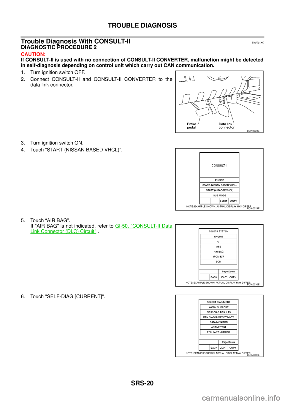
Trouble Diagnosis With CONSULT-II
EHS001XO
DIAGNOSTIC PROCEDURE 2
CAUTION:
If CONSULT-II is used with no connection of CONSULT-II CONVERTER, malfunction might be detected
in self-diagnosis depending on control unit which carry out CAN communication.
1. Turn ignition switch OFF.
2. Connect CONSULT-II and CONSULT-II CONVERTER to the
data link connector.
3. Turn ignition switch ON.
4. Touch “START (NISSAN BASED VHCL)”.
5. Touch “AIR BAG”.
If "AIR BAG" is not indicated, refer toGI-50, "
CONSULT-II Data
Link Connector (DLC) Circuit".
6. Touch "SELF-DIAG [CURRENT]".
BBIA0538E
BCIA0029E
BCIA0030E
BCIA0031E
Page 2932 of 3171
![NISSAN NAVARA 2005 Repair Workshop Manual TROUBLE DIAGNOSIS
SRS-23
C
D
E
F
G
I
J
K
L
MA
B
SRS
PRE-TEN FRONT LH
[OPEN]
[B1086]lThe circuit for front LH seat belt pre-tensioner is open. 1. Visually check the wiring harness
connections.
2. Repla NISSAN NAVARA 2005 Repair Workshop Manual TROUBLE DIAGNOSIS
SRS-23
C
D
E
F
G
I
J
K
L
MA
B
SRS
PRE-TEN FRONT LH
[OPEN]
[B1086]lThe circuit for front LH seat belt pre-tensioner is open. 1. Visually check the wiring harness
connections.
2. Repla](/manual-img/5/57362/w960_57362-2931.png)
TROUBLE DIAGNOSIS
SRS-23
C
D
E
F
G
I
J
K
L
MA
B
SRS
PRE-TEN FRONT LH
[OPEN]
[B1086]lThe circuit for front LH seat belt pre-tensioner is open. 1. Visually check the wiring harness
connections.
2. Replace the harness if it has visible
damage.
3. Replace front LH seat belt pre-
tensioner.
(Before disposal, it must be
deployed.)
4. Replace the air bag diagnosis sen-
sor unit.
5. Replace the related harness. PRE-TEN FRONT LH
[VB-SHORT]
[B1087]
lThe circuit for front LH seat belt pre-tensioner is shorted to
some power supply circuit.
PRE-TEN FRONT LH
[GND-SHORT]
[B1088]
lThe circuit for front LH seat belt pre-tensioner is shorted to
ground.
PRE-TEN FRONT LH
[SHORT]
[B1089]
lThe circuits for the front LH seat belt pre-tensioner are
shorted to each other.
PRE-TEN FRONT RH
[OPEN]
[B1081]
lThe circuit for front RH seat belt pre-tensioner is open. 1. Visually check the wiring harness
connections.
2. Replace the harness if it has visible
damage.
3. Replace front RH seat belt pre-
tensioner.
(Before disposal, it must be
deployed.)
4. Replace the air bag diagnosis sen-
sor unit.
5. Replace the related harness. PRE-TEN FRONT RH
[VB-SHORT]
[B1082]
lThe circuit for front RH seat belt pre-tensioner is shorted to
some power supply circuit.
PRE-TEN FRONT RH
[GND-SHORT]
[B1083]
lThe circuit for front RH seat belt pre-tensioner is shorted to
ground.
PRE-TEN FRONT RH
[SHORT]
[B1084]
lThe circuits for the front RH seat belt pre-tensioner are
shorted to each other.
CURTAIN MODULE LH
[OPEN]
[B1150]
lThe circuit for LH side curtain air bag module is open. 1. Visually check the wiring harness
connection.
2. Replace the harness if it has visible
damage.
3. Replace LH side curtain air bag
module.
(Before disposal, it must be
deployed.)
4. Replace the air bag diagnosis sen-
sor unit.
5. Replace the related harness. CURTAIN MODULE LH
[VB-SHORT]
[B1151]
lThe circuit for LH side curtain air bag module is shorted to
some power supply circuits.
CURTAIN MODULE LH
[GND-SHORT]
[B1152]
lThe circuit for LH side curtain air bag module is shorted to
ground.
CURTAIN MODULE LH
[SHORT]
[B1153]
lThe circuits for the LH side curtain air bag module are
shorted to each other.
CURTAIN MODULE RH
[OPEN]
[B1145]
lThe circuit for RH side curtain air bag module is open. 1. Visually check the wiring harness
connection.
2. Replace the harness if it has visible
damage.
3. Replace RH side curtain air bag
module.
(Before disposal, it must be
deployed.)
4. Replace the air bag diagnosis sen-
sor unit.
5. Replace the related harness. CURTAIN MODULE RH
[VB-SHORT]
[B1146]
lThe circuit for RH side curtain air bag module is shorted to
some power supply circuits.
CURTAIN MODULE RH
[GND-SHORT]
[B1147]
lThe circuit for RH side curtain air bag module is shorted to
ground.
CURTAIN MODULE RH
[SHORT]
[B1148]
lThe circuits for the RH side curtain air bag module are
shorted to each other.
CONTROL UNIT
[B1XXX]
lAir bag diagnosis sensor unit is malfunctioning. 1. Visually check the wiring harness
connection.
2. Replace the harness if it has visible
damage.
3. Replace the air bag diagnosis sen-
sor unit. Diagnostic item ExplanationRepair order
Recheck SRS at each replacement
Page 2933 of 3171

SRS-24
TROUBLE DIAGNOSIS
NOTE:
Follow the procedures in numerical order when repairing malfunctioning parts. Confirm whether malfunction is
eliminated using air bag warning lamp or CONSULT-II each time repair is finished. If malfunction is still
observed, proceed to the next step. When malfunction is eliminated, further repair work is not required.
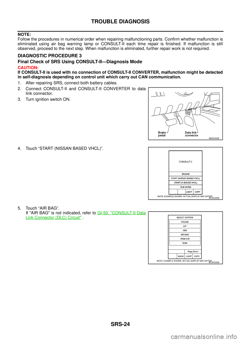
DIAGNOSTIC PROCEDURE 3
Final Check of SRS Using CONSULT-II—Diagnosis Mode
CAUTION:
If CONSULT-II is used with no connection of CONSULT-II CONVERTER, malfunction might be detected
in self-diagnosis depending on control unit which carry out CAN communication.
1. After repairing SRS, connect both battery cables.
2. Connect CONSULT-II and CONSULT-II CONVERTER to data
link connector.
3. Turn ignition switch ON.
4. Touch “START (NISSAN BASED VHCL)”.
5. Touch “AIR BAG”.
If "AIR BAG" is not indicated, refer toGI-50, "
CONSULT-II Data
Link Connector (DLC) Circuit".
BBIA0538E
BCIA0029E
BCIA0030E
Page 2935 of 3171

SRS-26
TROUBLE DIAGNOSIS
DIAGNOSTIC PROCEDURE 4 (CONTINUED FROM DIAGNOSTIC PROCEDURE 2)
Check SRS Repair History
1.CONSIDER POSSIBILITY THAT SELF-DIAGNOSTIC RESULT WAS NOT ERASED AFTER REPAIR
Check repair history of the SRS.
Have any previous repairs been made to the SRS?
Yes >> Self-diagnostic result “SELF-DIAG [PAST]” (previously stored in the memory) might not be erased
after repair. Go toSRS-24, "
DIAGNOSTIC PROCEDURE 3".
No >> Go toSRS-20, "
DIAGNOSTIC PROCEDURE 2".
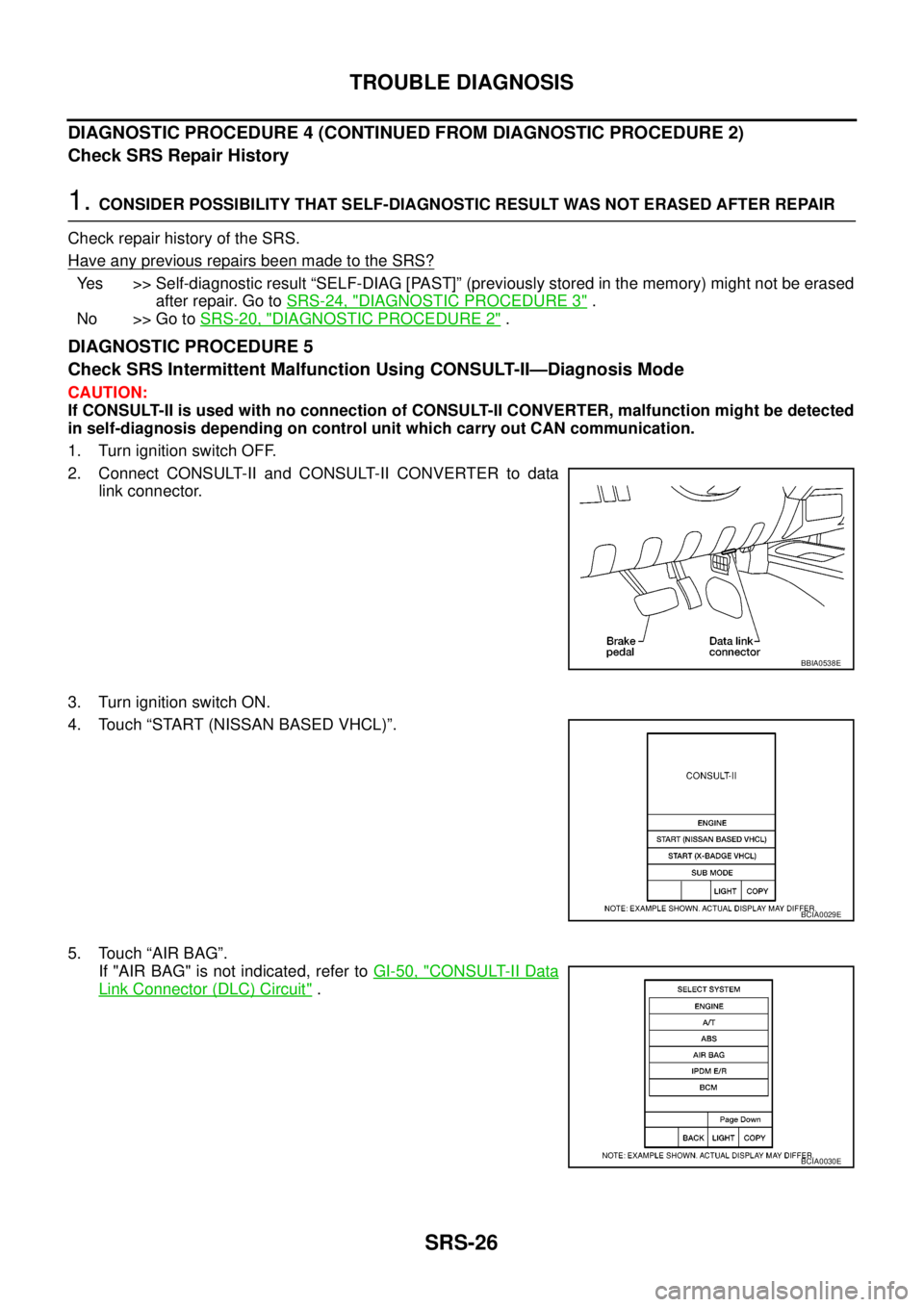
DIAGNOSTIC PROCEDURE 5
Check SRS Intermittent Malfunction Using CONSULT-II—Diagnosis Mode
CAUTION:
If CONSULT-II is used with no connection of CONSULT-II CONVERTER, malfunction might be detected
in self-diagnosis depending on control unit which carry out CAN communication.
1. Turn ignition switch OFF.
2. Connect CONSULT-II and CONSULT-II CONVERTER to data
link connector.
3. Turn ignition switch ON.
4. Touch “START (NISSAN BASED VHCL)”.
5. Touch “AIR BAG”.
If "AIR BAG" is not indicated, refer toGI-50, "
CONSULT-II Data
Link Connector (DLC) Circuit".
BBIA0538E
BCIA0029E
BCIA0030E