2005 NISSAN NAVARA check engine
[x] Cancel search: check enginePage 2979 of 3171

TF-12
TRANSFER FLUID
TRANSFER FLUID
PFP:31001
ReplacementEDS0031H
DRAINING
1. Stop engine.
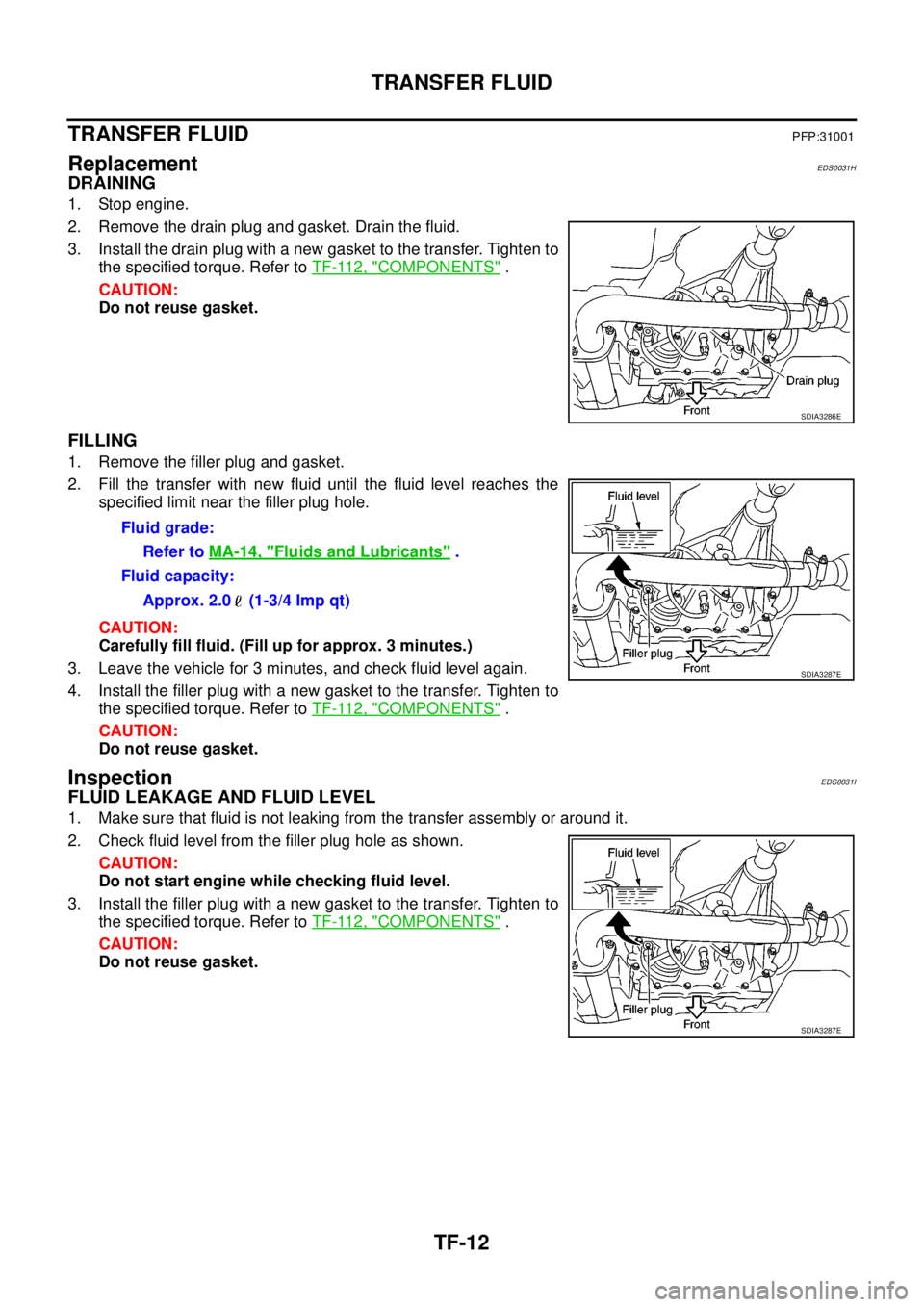
2. Remove the drain plug and gasket. Drain the fluid.
3. Install the drain plug with a new gasket to the transfer. Tighten to
the specified torque. Refer toTF-112, "
COMPONENTS".
CAUTION:
Do not reuse gasket.
FILLING
1. Remove the filler plug and gasket.
2. Fill the transfer with new fluid until the fluid level reaches the
specified limit near the filler plug hole.
CAUTION:
Carefully fill fluid. (Fill up for approx. 3 minutes.)
3. Leave the vehicle for 3 minutes, and check fluid level again.
4. Install the filler plug with a new gasket to the transfer. Tighten to
the specified torque. Refer toTF-112, "
COMPONENTS".
CAUTION:
Do not reuse gasket.
InspectionEDS0031I
FLUID LEAKAGE AND FLUID LEVEL
1. Make sure that fluid is not leaking from the transfer assembly or around it.
2. Check fluid level from the filler plug hole as shown.
CAUTION:
Do not start engine while checking fluid level.
3. Install the filler plug with a new gasket to the transfer. Tighten to
the specified torque. Refer toTF-112, "
COMPONENTS".
CAUTION:
Do not reuse gasket.
SDIA3286E
Fluid grade:
Refer toMA-14, "
Fluids and Lubricants".
Fluid capacity:
Approx. 2.0 (1-3/4 Imp qt)
SDIA3287E
SDIA3287E
Page 2983 of 3171

TF-16
4WD SYSTEM
4WD SHIFT SWITCH AND INDICATOR LAMP
4WD Shift Switch
4WD shift switch is able to select from 2WD, 4H or 4LO.
4WD Shift Indicator Lamp
lDisplays driving conditions selected by 4WD shift switch with front, rear and center indicators, while
engine is running. (When shifting from 4H to 4LO, 4LO indicator lamp also turns on. And when 4WD warn-
ing lamp is turned on, all 4WD shift indicator lamps are turned off.)
lTurns ON when ignition switch is turned ON, for purpose of lamp check. Turns OFF approximately 1 sec-
ondaftertheenginestartsifsystemisnormal.
4LO Indicator Lamp
lDisplays 4LO condition while engine is running. 4LO indicator lamp flashes if transfer gear does not shift
completely under 4HÛ4LO. In this condition, transfer may be under neutral condition and A/T parking
mechanism may not operate.
lTurns ON when ignition switch is turned ON, for purpose of lamp check. Turns OFF approximately 1 sec-
ondaftertheenginestartsifsystemisnormal.
SDIA3290E
Page 2984 of 3171

4WD SYSTEM
TF-17
C
E
F
G
H
I
J
K
L
MA
B
TF
4WD WARNING LAMP
Turns ON or flashes when there is a malfunction in 4WD system.
Also turns ON when ignition switch is turned ON, for purpose of lamp check. Turns OFF approximately 1 sec-
ond after the engine starts if system is normal.
4WD Warning Lamp Indication
NOTE:
4WD warning lamp is turned on when the following one or more parts are malfunctioning.
lVehicle speed signal
[from ABS actuator and electric unit (control unit)]
lCAN communication line
lAD converter
lEngine speed signal
l4WD shift switch
lWait detection switch
lActuator motor
lTransfer control device
lTransfer shut off relay
lTransfer shift relay
lPNP switch signal
ATP WARNING LAMP (A/T MODELS)
When A/T selector lever is in “P” position, vehicle may move because A/T parking mechanism does not oper-
ate when transfer is under neutral condition. ATP warning lamp is turned on to indicate this condition to the
driver.
Condition 4WD warning lamp
Lamp checkTurns ON when ignition switch is turned ON.
Turns OFF after engine start.
4WD system malfunctionON
(For indicated malfunction items, see the “NOTE”)
During self-diagnosis Flashes at malfunction mode.
Large difference in diameter of front/
rear tiresSlow flashing: 1 time/2 seconds
(Continues to flash until ignition switch is turned OFF)
Other than above (system normal) OFF
Page 3005 of 3171

TF-38
TROUBLE DIAGNOSIS
Trouble Diagnosis Chart for Symptoms
EDS0031U
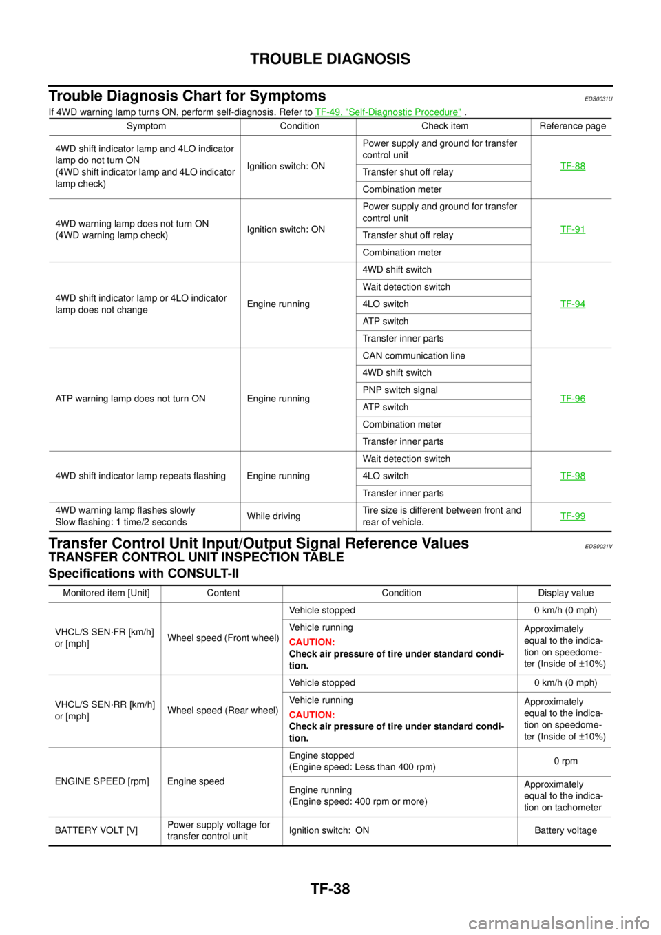
If 4WD warning lamp turns ON, perform self-diagnosis. Refer toTF-49, "Self-Diagnostic Procedure".
Transfer Control Unit Input/Output Signal Reference ValuesEDS0031V
TRANSFER CONTROL UNIT INSPECTION TABLE
Specifications with CONSULT-II
Symptom Condition Check item Reference page
4WD shift indicator lamp and 4LO indicator
lamp do not turn ON
(4WD shift indicator lamp and 4LO indicator
lamp check)Ignition switch: ONPower supply and ground for transfer
control unit
TF-88
Transfer shut off relay
Combination meter
4WD warning lamp does not turn ON
(4WD warning lamp check)Ignition switch: ONPower supply and ground for transfer
control unit
TF-91
Transfer shut off relay
Combination meter
4WD shift indicator lamp or 4LO indicator
lamp does not changeEngine running4WD shift switch
TF-94
Wait detection switch
4LO switch
AT P s w i t c h
Transfer inner parts
ATP warning lamp does not turn ON Engine runningCAN communication line
TF-96
4WD shift switch
PNP switch signal
AT P s w i t c h
Combination meter
Transfer inner parts
4WD shift indicator lamp repeats flashing Engine runningWait detection switch
TF-98
4LO switch
Transfer inner parts
4WD warning lamp flashes slowly
Slow flashing: 1 time/2 secondsWhile drivingTire size is different between front and
rear of vehicle.TF-99
Monitored item [Unit] Content Condition Display value
VHCL/S SEN·FR [km/h]
or [mph]Wheel speed (Front wheel)Vehicle stopped 0 km/h (0 mph)
Vehicle running
CAUTION:
Check air pressure of tire under standard condi-
tion.Approximately
equal to the indica-
tion on speedome-
ter (Inside of±10%)
VHCL/S SEN·RR [km/h]
or [mph]Wheel speed (Rear wheel)Vehicle stopped 0 km/h (0 mph)
Vehicle running
CAUTION:
Check air pressure of tire under standard condi-
tion.Approximately
equal to the indica-
tion on speedome-
ter (Inside of±10%)
ENGINE SPEED [rpm] Engine speedEngine stopped
(Engine speed: Less than 400 rpm)0rpm
Engine running
(Engine speed: 400 rpm or more)Approximately
equal to the indica-
tion on tachometer
BATTERY VOLT [V]Power supply voltage for
transfer control unitIgnition switch: ON Battery voltage
Page 3006 of 3171
![NISSAN NAVARA 2005 Repair Workshop Manual TROUBLE DIAGNOSIS
TF-39
C
E
F
G
H
I
J
K
L
MA
B
TF
2WDSWITCH[ON/
OFF]Input condition from 4WD
shift switch4WD shift switch: 2WD ON
4WD shift switch: 4H and 4LO OFF
4H SWITCH [ON/OFF]Input condition fro NISSAN NAVARA 2005 Repair Workshop Manual TROUBLE DIAGNOSIS
TF-39
C
E
F
G
H
I
J
K
L
MA
B
TF
2WDSWITCH[ON/
OFF]Input condition from 4WD
shift switch4WD shift switch: 2WD ON
4WD shift switch: 4H and 4LO OFF
4H SWITCH [ON/OFF]Input condition fro](/manual-img/5/57362/w960_57362-3005.png)
TROUBLE DIAGNOSIS
TF-39
C
E
F
G
H
I
J
K
L
MA
B
TF
2WDSWITCH[ON/
OFF]Input condition from 4WD
shift switch4WD shift switch: 2WD ON
4WD shift switch: 4H and 4LO OFF
4H SWITCH [ON/OFF]Input condition from 4WD
shift switch4WD shift switch: 4H ON
4WD shift switch: 2WD and 4LO OFF
4L SWITCH [ON/OFF]Input condition from 4WD
shift switch4WD shift switch: 4LO ON
4WD shift switch: 2WD and 4H OFF
4L POSI SW [ON/OFF] Condition of 4LO switch
lVehicle stopped
lEngine running
lFor A/T models, A/T
selector lever “N” posi-
tion with brake pedal
depressed.
lFor M/T models, M/T
shift lever neutral posi-
tion with clutch and
brake pedal depressed.4WD shift switch: 4LO ON
Except the above OFF
ATP SWITCH [ON/OFF] Condition of ATP switch
lVehicle stopped
lEngine running
lA/T selector lever “N”
position with brake
pedal depressed.4WD shift switch:
4H to 4LO or 4LO to 4H
(While actuator motor is
operating.)ON
Except the above OFF
WAIT DETCT SW [ON/
OFF]Condition of wait detection
switch
lVehicle stopped
lEngine running
lFor A/T models, A/T
selector lever “N” posi-
tion with brake pedal
depressed.
lFor M/T models, M/T
shift lever neutral posi-
tion with clutch and
brake pedal depressed.4WD shift switch:
4H and 4LOON
4WD shift switch: 2WD OFF
4WD MODE [2H/4H/4L]Control status of 4WD
(Output condition of 4WD
shift indicator lamp and
4LO indicator lamp)4WD shift switch
(Engine running)2WD 2H
4H 4H
4LO 4L
VHCL/S COMP [km/h]
or [mph]Vehicle speedVehicle stopped 0 km/h (0 mph)
Vehicle running
CAUTION:
Check air pressure of tires under standard condi-
tion.Approximately
equal to the indica-
tion on speedome-
ter (Inside of±10%)
SHIFT ACT 1 [ON/OFF]Output condition to actua-
tor motor (clockwise)
lVehicle stopped
lEngine running
lFor A/T models, A/T
selector lever “N” posi-
tion with brake pedal
depressed.
lFor M/T models, M/T
shift lever neutral posi-
tion with clutch and
brake pedal depressed.4WD shift switch:
2WDto4Hor4Hto4LO
or 2WD to 4LOON
Except the above OFF Monitored item [Unit] Content Condition Display value
Page 3007 of 3171
![NISSAN NAVARA 2005 Repair Workshop Manual TF-40
TROUBLE DIAGNOSIS
SHIFT AC MON1 [ON/
OFF]Check signal for transfer
control unit signal output
lVehicle stopped
lEngine running
lFor A/T models, A/T
selector lever “N” posi-
tion with brake p NISSAN NAVARA 2005 Repair Workshop Manual TF-40
TROUBLE DIAGNOSIS
SHIFT AC MON1 [ON/
OFF]Check signal for transfer
control unit signal output
lVehicle stopped
lEngine running
lFor A/T models, A/T
selector lever “N” posi-
tion with brake p](/manual-img/5/57362/w960_57362-3006.png)
TF-40
TROUBLE DIAGNOSIS
SHIFT AC MON1 [ON/
OFF]Check signal for transfer
control unit signal output
lVehicle stopped
lEngine running
lFor A/T models, A/T
selector lever “N” posi-
tion with brake pedal
depressed.
lFor M/T models, M/T
shift lever neutral posi-
tion with clutch and
brake pedal depressed.4WD shift switch:
2WDto4Hor4Hto4LO
or 2WD to 4LOON
Except the above OFF
SHIFT ACT 2 [ON/OFF]Output condition to actua-
tor motor (counterclock-
wise)
lVehicle stopped
lEngine running
lFor A/T models, A/T
selector lever “N” posi-
tion with brake pedal
depressed.
lFor M/T models, M/T
shift lever neutral posi-
tion with clutch and
brake pedal depressed.4WD shift switch:
4LOto4Hor4Hto2WD
or 4LO to 2WDON
Except the above OFF
SHIFT AC MON2 [ON/
OFF]Check signal for transfer
control unit signal output
lVehicle stopped
lEngine running
lFor A/T models, A/T
selector lever “N” posi-
tion with brake pedal
depressed.
lFor M/T models, M/T
shift lever neutral posi-
tion with clutch and
brake pedal depressed.4WD shift switch:
4LOto4Hor4Hto2WD
or 4LO to 2WDON
Except the above OFF
SHIFT ACT/R MON
[ON/OFF]Operating condition of
actuator motor relay (inte-
grated in transfer control
unit)
lVehicle stopped
lEngine running
lFor A/T models, A/T
selector lever “N” posi-
tion with brake pedal
depressed.
lFor M/T models, M/T
shift lever neutral posi-
tion with clutch and
brake pedal depressed.When 4WD shift switch is
operatedON
When 4WD shift switch is
not operatedOFF
SHIFT POS SW1 [ON/
OFF]Condition of actuator posi-
tion switch 1
lVehicle stopped
lEngine running
lFor A/T models, A/T
selector lever “N” posi-
tion with brake pedal
depressed.
lFor M/T models, M/T
shift lever neutral posi-
tion with clutch and
brake pedal depressed.4WD shift switch:
2WD and 4LOON
4WD shift switch: 4H OFF
SHIFT POS SW2 [ON/
OFF]Condition of actuator posi-
tion switch 24WD shift switch: 4LO ON
4WD shift switch:
2WD and 4HOFF
SHIFT POS SW3 [ON/
OFF]Condition of actuator posi-
tion switch 34WD shift switch:
2WD and 4HON
4WD shift switch: 4LO OFF
SHIFT POS SW4 [ON/
OFF]Condition of actuator posi-
tion switch 44WD shift switch:
4H and 4LOON
4WD shift switch: 2WD OFF
4WD FAIL LAMP [ON/
OFF]4WD warning lamp condi-
tion4WD warning lamp: ON ON
4WD warning lamp: OFF OFF Monitored item [Unit] Content Condition Display value
Page 3012 of 3171

TROUBLE DIAGNOSIS
TF-45
C
E
F
G
H
I
J
K
L
MA
B
TF
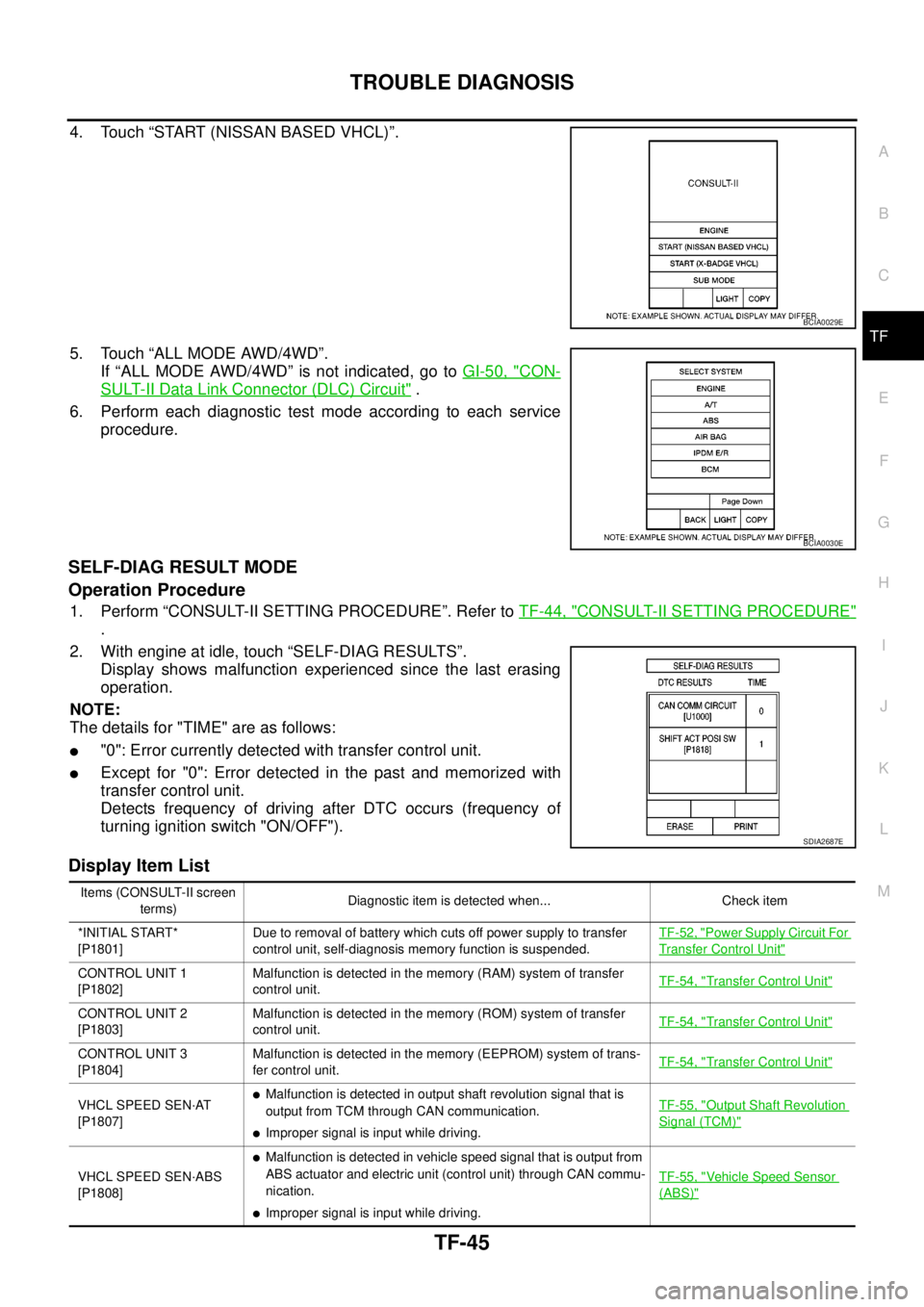
4. Touch “START (NISSAN BASED VHCL)”.
5. Touch “ALL MODE AWD/4WD”.
If “ALL MODE AWD/4WD” is not indicated, go toGI-50, "
CON-
SULT-II Data Link Connector (DLC) Circuit".
6. Perform each diagnostic test mode according to each service
procedure.
SELF-DIAG RESULT MODE
Operation Procedure
1. Perform “CONSULT-II SETTING PROCEDURE”. Refer toTF-44, "CONSULT-II SETTING PROCEDURE"
.
2. With engine at idle, touch “SELF-DIAG RESULTS”.
Display shows malfunction experienced since the last erasing
operation.
NOTE:
The details for "TIME" are as follows:
l"0": Error currently detected with transfer control unit.
lExcept for "0": Error detected in the past and memorized with
transfer control unit.
Detects frequency of driving after DTC occurs (frequency of
turning ignition switch "ON/OFF").
Display Item List
BCIA0029E
BCIA0030E
SDIA2687E
Items (CONSULT-II screen
terms)Diagnostic item is detected when... Check item
*INITIAL START*
[P1801]Due to removal of battery which cuts off power supply to transfer
control unit, self-diagnosis memory function is suspended.TF-52, "
Power Supply Circuit For
Transfer Control Unit"
CONTROL UNIT 1
[P1802]Malfunction is detected in the memory (RAM) system of transfer
control unit.TF-54, "Transfer Control Unit"
CONTROL UNIT 2
[P1803]Malfunction is detected in the memory (ROM) system of transfer
control unit.TF-54, "Transfer Control Unit"
CONTROL UNIT 3
[P1804]Malfunction is detected in the memory (EEPROM) system of trans-
fer control unit.TF-54, "Transfer Control Unit"
VHCL SPEED SEN·AT
[P1807]lMalfunction is detected in output shaft revolution signal that is
output from TCM through CAN communication.
lImproper signal is input while driving.TF-55, "
Output Shaft Revolution
Signal (TCM)"
VHCL SPEED SEN·ABS
[P1808]
lMalfunction is detected in vehicle speed signal that is output from
ABS actuator and electric unit (control unit) through CAN commu-
nication.
lImproper signal is input while driving.TF-55, "
Vehicle Speed Sensor
(ABS)"
Page 3013 of 3171
![NISSAN NAVARA 2005 Repair Workshop Manual TF-46
TROUBLE DIAGNOSIS
CAUTION:
If “CAN COMM CIRCUIT [U1000]” is displayed with other DTCs, first perform the trouble diagnosis for CAN communication
line.
NOTE:
If “SHIFT ACT POSI SW [P1818]� NISSAN NAVARA 2005 Repair Workshop Manual TF-46
TROUBLE DIAGNOSIS
CAUTION:
If “CAN COMM CIRCUIT [U1000]” is displayed with other DTCs, first perform the trouble diagnosis for CAN communication
line.
NOTE:
If “SHIFT ACT POSI SW [P1818]�](/manual-img/5/57362/w960_57362-3012.png)
TF-46
TROUBLE DIAGNOSIS
CAUTION:
If “CAN COMM CIRCUIT [U1000]” is displayed with other DTCs, first perform the trouble diagnosis for CAN communication
line.
NOTE:
If “SHIFT ACT POSI SW [P1818]” or “SHIFT ACT CIR [P1819]” is displayed, first erase self-diagnostic results. (“SHIFT ACT POSI SW
[P1818]” or “SHIFT ACT CIR [P1819]” may be displayed after installing transfer control unit or transfer assembly.)
How to Erase Self-diagnostic Results
1. Perform applicable inspection of malfunctioning item and then repair or replace.
2. Start engine and select “SELF-DIAG RESULTS” mode for “ALL MODE AWD/4WD” with CONSULT-II.
3. Touch “ERASE” on CONSULT-II screen to erase DTC memory.
CAUTION:
If memory cannot be erased, perform applicable diagnosis.
CONTROL UNIT 4
[P1809]AD converter system of transfer control unit is malfunctioning.TF-54, "Transfer Control Unit"
4L POSI SW TF
[P1810]Improper signal from 4LO switch is input due to open or short circuit.TF-56, "4LO Switch"
BATTERY VOLTAGE
[P1811]Power supply voltage for transfer control unit is abnormally low
while driving.TF-52, "Power Supply Circuit For
Transfer Control Unit"
4WD MODE SW
[P1813]More than two switch inputs are simultaneously detected due to
short circuit of 4WD shift switch.TF-59, "4WD Shift Switch"
4WD DETECT SWITCH
[P1814]Improper signal from wait detection switch is input due to open or
short circuit.TF-63, "Wait Detection Switch"
PNP SW/CIRC
[P1816]When A/T PNP switch signal is malfunction or communication error
between the vehicles.TF-66, "PNP Switch Signal
(TCM)"
SHIFT ACTUATOR
[P1817]
lMotor does not operate properly due to open or short circuit in
actuator motor.
lMalfunction is detected in the actuator motor. (When 4WD shift
switch is operated and actuator motor is not operated)
lMalfunction is detected in transfer shift high relay and transfer
shift low relay.TF-67, "
Actuator Motor"
SHIFT ACT POSI SW
[P1818]lImproper signal from actuator position switch is input due to open
or short circuit.
lMalfunction is detected in actuator position switch.TF-75, "
Actuator Position
Switch"
SHIFT ACT CIR
[P1819]lMalfunction is detected in transfer shut off relay 1 and transfer
shut off relay 2.
lMalfunction occurs in transfer control device drive circuit.TF-52, "
Power Supply Circuit For
Transfer Control Unit",TF-78,
"Transfer Control Device"
ENGINE SPEED SIG
[P1820]lMalfunction is detected in engine speed signal that is output from
ECM through CAN communication.
lImproper signal is input while driving.TF-81, "
Engine Speed Signal
(ECM)"
CAN COMM CIRCUIT
[U1000]Malfunction has been detected from CAN communication line.TF-82, "CAN Communication
Line"
NO DTC IS DETECTED.
FURTHER TESTING MAY
BE REQUIRED.No NG item has been detected. — Items (CONSULT-II screen
terms)Diagnostic item is detected when... Check item