2005 NISSAN NAVARA check engine
[x] Cancel search: check enginePage 2838 of 3171
BATTERY
SC-5
C
D
E
F
G
H
I
J
L
MA
B
SC
BATTERYPFP:00011
How to Handle BatteryEKS00MZ7
CAUTION:
lIf it becomes necessary to start the engine with a booster battery and jumper cables, use a 12-volt
booster battery.
lAfter connecting battery cables, ensure that they are tightly clamped to battery terminals for good
contact.
lNever add distilled water through the hole used to check specific gravity.
METHODS OF PREVENTING OVER-DISCHARGE
The following precautions must be taken to prevent over-discharging a battery.
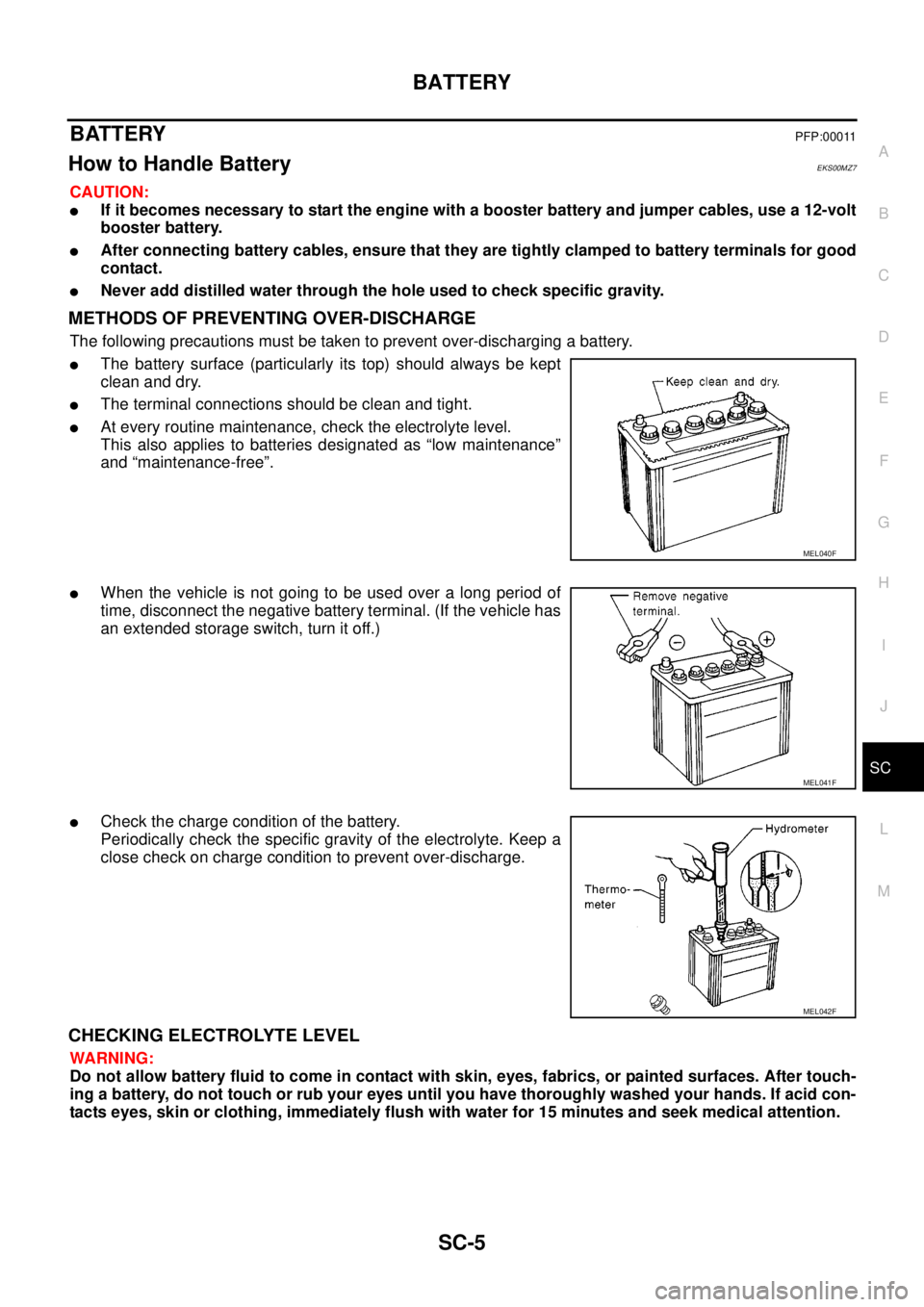
lThe battery surface (particularly its top) should always be kept
clean and dry.
lThe terminal connections should be clean and tight.
lAt every routine maintenance, check the electrolyte level.
This also applies to batteries designated as “low maintenance”
and “maintenance-free”.
lWhen the vehicle is not going to be used over a long period of
time, disconnect the negative battery terminal. (If the vehicle has
an extended storage switch, turn it off.)
lCheck the charge condition of the battery.
Periodically check the specific gravity of the electrolyte. Keep a
close check on charge condition to prevent over-discharge.
CHECKING ELECTROLYTE LEVEL
WARNING:
Do not allow battery fluid to come in contact with skin, eyes, fabrics, or painted surfaces. After touch-
ing a battery, do not touch or rub your eyes until you have thoroughly washed your hands. If acid con-
tacts eyes, skin or clothing, immediately flush with water for 15 minutes and seek medical attention.
MEL040F
MEL041F
MEL042F
Page 2849 of 3171
SC-16
CHARGING SYSTEM
Trouble Diagnosis
EKS00MZD
DIAGNOSIS PROCEDURE
1. Check malfunction symptoms or customer's remarks.
2. Perform pre-diagnosis inspection. Refer toSC-16, "
PRE-DIAGNOSIS INSPECTION".
3. Perform trouble diagnosis for each trouble symptom. Refer toSC-16, "
DIAGNOSIS CHART BY SYMP-
TOM"
4. Repair or replace parts indicated inspection flow based on the charge warning lamp. Refer toSC-16,
"INSPECTION FLOW BY CHARGE WARNING LAMP".
5. End
PRE-DIAGNOSIS INSPECTION
1. Perform alternator belt inspection. Refer toEM-12, "DRIVE BELTS".
2. Inspect battery.
3. Check alternator terminal 1 for loose or improper connection.
4. Check alternator connector 4 and 3 terminals for loose connection, disconnection and bend.
5. Check connecting condition of harness for charging system harness (fusible link terminal and battery ter-
minal).
6. After performing 1 to 5 above, go to trouble diagnosis for symptoms. Refer toSC-16, "
DIAGNOSIS
CHART BY SYMPTOM".
DIAGNOSIS CHART BY SYMPTOM
INSPECTION FLOW BY CHARGE WARNING LAMP
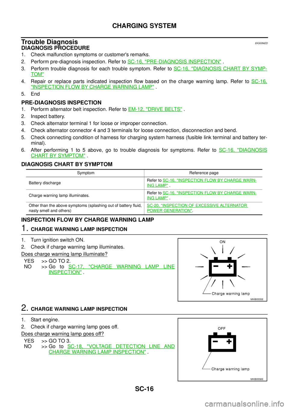
1.CHARGE WARNING LAMP INSPECTION
1. Turn ignition switch ON.
2. Check if charge warning lamp illuminates.
Does charge warning lamp illuminate?
YES >> GO TO 2.
NO >> Go toSC-17, "
CHARGE WARNING LAMP LINE
INSPECTION".
2.CHARGE WARNING LAMP INSPECTION
1. Start engine.
2. Check if charge warning lamp goes off.
Does charge warning lamp goes off?
YES >> GO TO 3.
NO >> Go toSC-18, "
VOLTAGE DETECTION LINE AND
CHARGE WARNING LAMP INSPECTION".
Symptom Reference page
Battery dischargeRefer toSC-16, "
INSPECTION FLOW BY CHARGE WARN-
ING LAMP".
Charge warning lamp illuminates.Refer toSC-16, "
INSPECTION FLOW BY CHARGE WARN-
ING LAMP".
Other than the above symptoms (splashing out of battery fluid,
nasty smell and others)SC-20, "
INSPECTION OF EXCESSIVE ALTERNATOR
POWER GENERATION".
MKIB0555E
MKIB0556E
Page 2850 of 3171
CHARGING SYSTEM
SC-17
C
D
E
F
G
H
I
J
L
MA
B
SC
3.CHARGE WARNING LAMP INSPECTION
1. Set engine speed at 2,500 rpm.
2. Check if charge warning lamp illuminates.
Does charge warning lamp illuminate?
YES >> Go toSC-20, "INSPECTION OF EXCESSIVE ALTER-
NATOR POWER GENERATION".
NO >> Go toSC-20, "
INSPECTION OF INSUFFICIENT
ALTERNATOR POWER GENERATION".
CHARGE WARNING LAMP LINE INSPECTION
CAUTION:
If open circuit is detected in alternator connector terminal 3, alternator cannot start generating.
INSPECTION PROCEDURE
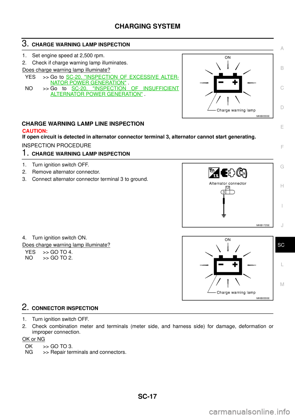
1.CHARGE WARNING LAMP INSPECTION
1. Turn ignition switch OFF.
2. Remove alternator connector.
3. Connect alternator connector terminal 3 to ground.
4. Turn ignition switch ON.
Does charge warning lamp illuminate?
YES >> GO TO 4.
NO >> GO TO 2.
2.CONNECTOR INSPECTION
1. Turn ignition switch OFF.
2. Check combination meter and terminals (meter side, and harness side) for damage, deformation or
improper connection.
OK or NG
OK >> GO TO 3.
NG >> Repair terminals and connectors.
MKIB0555E
MKIB1725E
MKIB0555E
Page 2853 of 3171
SC-20
CHARGING SYSTEM
INSPECTION OF INSUFFICIENT ALTERNATOR POWER GENERATION
CAUTION:
Check them using charged battery performed battery inspection.
1.VOLTAGE INSPECTION
1. Increase engine speed to 2,500 rpm.
2. Turn electrical load to ON. (Headlamp LO turns on, blower fan
motor maximum airflow amount)
3. Check battery voltage.
Is the inspection result 12.8V to 15.1V?
YES >> GO TO 2.
NO >> Replace alternator. (Alternator power generation error.)
2.CURRENT INSPECTION
1. Turn ignition switch OFF.
2. Disconnect the battery ground cable.
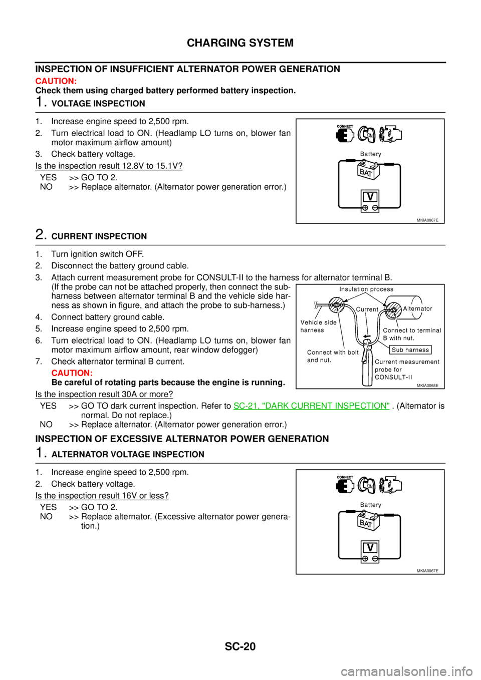
3. Attach current measurement probe for CONSULT-II to the harness for alternator terminal B.
(If the probe can not be attached properly, then connect the sub-
harness between alternator terminal B and the vehicle side har-
ness as shown in figure, and attach the probe to sub-harness.)
4. Connect battery ground cable.
5. Increase engine speed to 2,500 rpm.
6. Turn electrical load to ON. (Headlamp LO turns on, blower fan
motor maximum airflow amount, rear window defogger)
7. Check alternator terminal B current.
CAUTION:
Be careful of rotating parts because the engine is running.
Is the inspection result 30A or more?
YES >> GO TO dark current inspection. Refer toSC-21, "DARK CURRENT INSPECTION". (Alternator is
normal. Do not replace.)
NO >> Replace alternator. (Alternator power generation error.)
INSPECTION OF EXCESSIVE ALTERNATOR POWER GENERATION
1.ALTERNATOR VOLTAGE INSPECTION
1. Increase engine speed to 2,500 rpm.
2. Check battery voltage.
Is the inspection result 16V or less?
YES >> GO TO 2.
NO >> Replace alternator. (Excessive alternator power genera-
tion.)
MKIA0067E
MKIA0068E
MKIA0067E
Page 2856 of 3171
CHARGING SYSTEM
SC-23
C
D
E
F
G
H
I
J
L
MA
B
SC
Removal and InstallationEKS00MZE
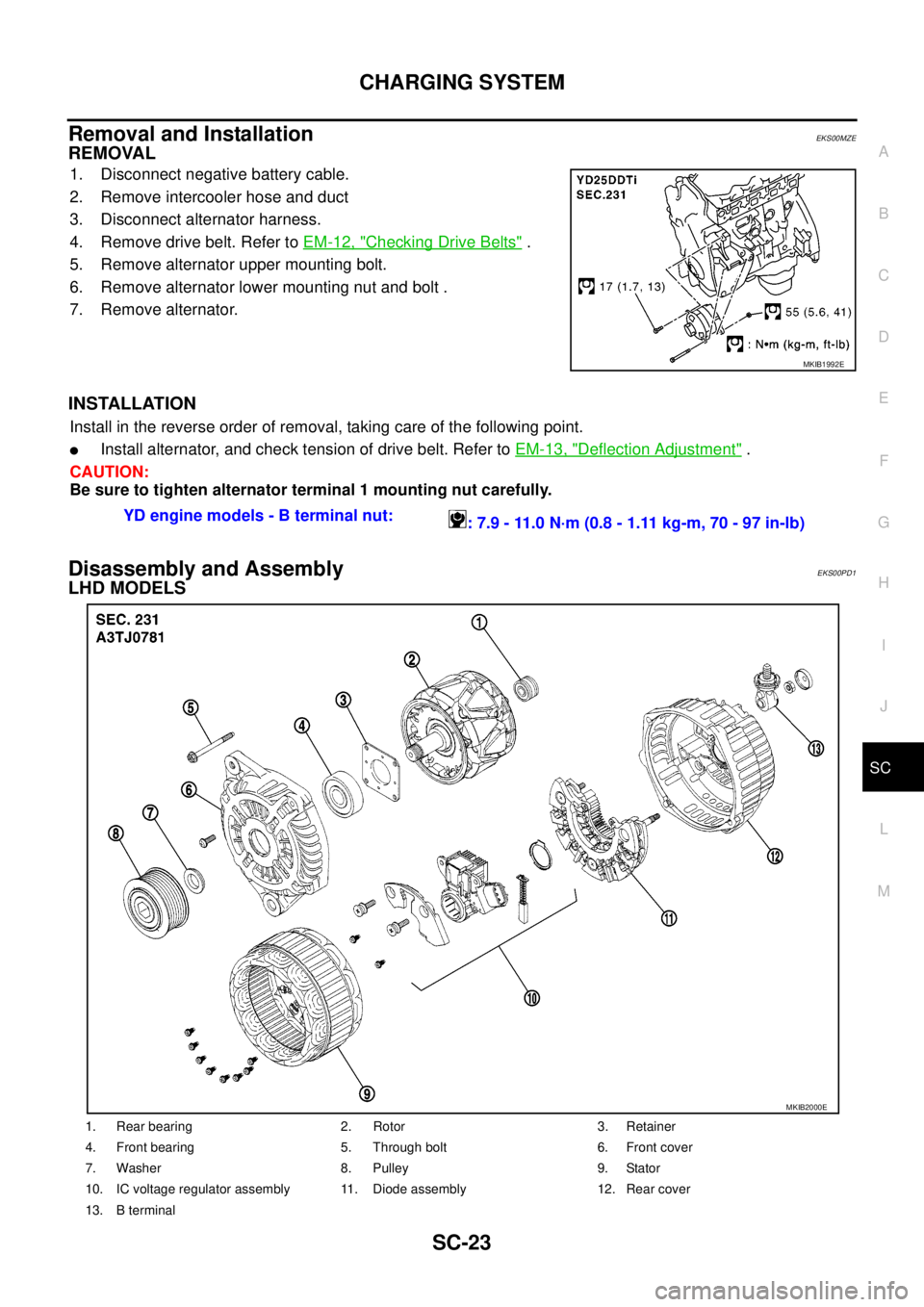
REMOVAL
1. Disconnect negative battery cable.
2. Remove intercooler hose and duct
3. Disconnect alternator harness.
4. Remove drive belt. Refer toEM-12, "
Checking Drive Belts".
5. Remove alternator upper mounting bolt.
6. Remove alternator lower mounting nut and bolt .
7. Remove alternator.
INSTALLATION
Install in the reverse order of removal, taking care of the following point.
lInstall alternator, and check tension of drive belt. Refer toEM-13, "Deflection Adjustment".
CAUTION:
Be sure to tighten alternator terminal 1 mounting nut carefully.
Disassembly and AssemblyEKS00PD1
LHD MODELS
MKIB1992E
YD engine models - B terminal nut:
: 7.9 - 11.0 N·m (0.8 - 1.11 kg-m, 70 - 97 in-lb)
1. Rear bearing 2. Rotor 3. Retainer
4. Front bearing 5. Through bolt 6. Front cover
7. Washer 8. Pulley 9. Stator
10. IC voltage regulator assembly 11. Diode assembly 12. Rear cover
13. B terminal
MKIB2000E
Page 2876 of 3171
SQUEAK AND RATTLE TROUBLE DIAGNOSES
SE-5
C
D
E
F
G
H
J
K
L
MA
B
SE
DUPLICATE THE NOISE AND TEST DRIVE
If possible, drive the vehicle with the customer until the noise is duplicated. Note any additional information on
the Diagnostic Worksheet regarding the conditions or location of the noise. This information can be used to
duplicate the same conditions when you confirm the repair.
If the noise can be duplicated easily during the test drive, to help identify the source of the noise, try to dupli-
cate the noise with the vehicle stopped by doing one or all of the following:
1) Close a door.
2) Tap or push/pull around the area where the noise appears to be coming from.
3) Rev the engine.
4) Use a floor jack to recreate vehicle “twist”.
5) At idle, apply engine load (electrical load, half-clutch on M/T models, drive position on A/T models).
6) Raisethevehicleonahoistandhitatirewitharubberhammer.
lDrive the vehicle and attempt to duplicate the conditions the customer states exist when the noise occurs.
lIf it is difficult to duplicate the noise, drive the vehicle slowly on an undulating or rough road to stress the
vehicle body.
CHECK RELATED SERVICE BULLETINS
After verifying the customer concern or symptom, check ASIST for Technical Service Bulletins (TSBs) related
to that concern or symptom.
If a TSB relates to the symptom, follow the procedure to repair the noise.
LOCATE THE NOISE AND IDENTIFY THE ROOT CAUSE
1. Narrow down the noise to a general area. To help pinpoint the source of the noise, use a listening tool
(Engine Ear or mechanics stethoscope).
2. Narrow down the noise to a more specific area and identify the cause of the noise by:
lremoving the components in the area that you suspect the noise is coming from.
Do not use too much force when removing clips and fasteners, otherwise clips and fastener can be broken
or lost during the repair, resulting in the creation of new noise.
ltapping or pushing/pulling the component that you suspect is causing the noise.
Do not tap or push/pull the component with excessive force, otherwise the noise will be eliminated only
temporarily.
lfeeling for a vibration with your hand by touching the component(s) that you suspect is (are) causing the
noise.
lplacing a piece of paper between components that you suspect are causing the noise.
llooking for loose components and contact marks.
Refer toSE-6, "
Generic Squeak and Rattle Troubleshooting".
REPAIR THE CAUSE
lIf the cause is a loose component, tighten the component securely.
lIf the cause is insufficient clearance between components:
–separate components by repositioning or loosening and retightening the component, if possible.
–insulate components with a suitable insulator such as urethane pads, foam blocks, felt cloth tape or ure-
thane tape are available through your authorized Nissan Parts Department.
CAUTION:
Do not use excessive force as many components are constructed of plastic and may be damaged.
NOTE:
Always check with the Parts Department for the latest parts information.
Each item can be ordered separately as needed.
URETHANE PADS [1.5 mm (0.059 in) thick]
Insulates connectors, harness, etc.
76268-9E005: 100´135 mm (3.94´5.31 in)/76884-71L01: 60´85 mm (2.36´3.35 in)/76884-71L02: 15´
25 mm (0.59´0.98 in)
INSULATOR (Foam blocks)
Insulates components from contact. Can be used to fill space behind a panel.
73982-9E000: 45 mm (1.77 in) thick, 50´50 mm (1.97´1.97 in)/73982-50Y00: 10 mm (0.39 in) thick, 50
´50 mm (1.97´1.97 in)
INSULATOR (Light foam block)
80845-71L00: 30 mm (1.18 in) thick, 30´50 mm (1.18´1.97 in)
Page 2971 of 3171
TF-4
PRECAUTIONS
PRECAUTIONS
PFP:00001
Precautions for Supplemental Restraint System (SRS) “AIR BAG” and “SEAT
BELT PRE-TENSIONER”
EDS003ID
The Supplemental Restraint System such as “AIR BAG” and “SEAT BELT PRE-TENSIONER”, used along
with a front seat belt, helps to reduce the risk or severity of injury to the driver and front passenger for certain
types of collision. Information necessary to service the system safely is included in the SRS and SB section of
this Service Manual.
WARNING:
lTo avoid rendering the SRS inoperative, which could increase the risk of personal injury or death
in the event of a collision which would result in air bag inflation, all maintenance must be per-
formed by an authorized NISSAN/INFINITI dealer.
lImproper maintenance, including incorrect removal and installation of the SRS, can lead to per-
sonal injury caused by unintentional activation of the system. For removal of Spiral Cable and Air
Bag Module, see the SRS section.
lDo not use electrical test equipment on any circuit related to the SRS unless instructed to in this
Service Manual. SRS wiring harnesses can be identified by yellow and/or orange harnesses or
harness connectors.
Precautions for Transfer Assembly and Transfer Control Unit ReplacementEDS0031A
lWhen replacing transfer assembly or transfer control unit, check the 4WD shift indicator pattern and
adjustment of the position between transfer assembly and transfer control unit if necessary.
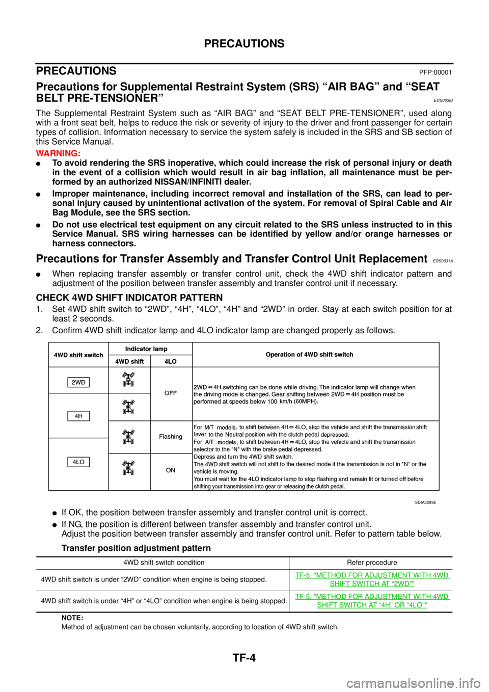
CHECK 4WD SHIFT INDICATOR PATTERN
1. Set 4WD shift switch to “2WD”, “4H”, “4LO”, “4H” and “2WD” in order. Stay at each switch position for at
least 2 seconds.
2. Confirm 4WD shift indicator lamp and 4LO indicator lamp are changed properly as follows.
lIf OK, the position between transfer assembly and transfer control unit is correct.
lIf NG, the position is different between transfer assembly and transfer control unit.
Adjust the position between transfer assembly and transfer control unit. Refer to pattern table below.
Transfer position adjustment pattern
NOTE:
Method of adjustment can be chosen voluntarily, according to location of 4WD shift switch.
SDIA3289E
4WD shift switch condition Refer procedure
4WD shift switch is under “2WD” condition when engine is being stopped.TF-5, "
METHOD FOR ADJUSTMENT WITH 4WD
SHIFT SWITCH AT“2WD”"
4WD shift switch is under “4H” or “4LO” condition when engine is being stopped.TF-5, "METHOD FOR ADJUSTMENT WITH 4WD
SHIFT SWITCH AT“4H”OR“4LO”"
Page 2972 of 3171
PRECAUTIONS
TF-5
C
E
F
G
H
I
J
K
L
MA
B
TF
METHODFORADJUSTMENTWITH4WDSHIFTSWITCHAT“2WD”
Select Adjustment Pattern
1. Start engine. Run engine for at least 10 seconds.
2. Check 4WD shift indicator lamp and 4LO indicator lamp.
Pattern A
1. Stay in the below for at least 2 seconds.
lFor A/T models, stop the vehicle and move A/T selector lever to “N” position with the brake pedal
depressed.
lFor M/T models, stop the vehicle and move M/T shift lever to the neutral position with the brake and
clutch pedal depressed.
2. Turn 4WD shift switch to “4LO” position. Stay in "4LO" for at least 2 seconds.
3. Turn ignition switch “OFF”.
4. Start engine.
5. Erase self-diagnosis. Refer toTF-46, "
How to Erase Self-diagnostic Results"(with CONSULT-II) orTF-
51, "ERASE SELF-DIAGNOSIS"(without CONSULT-II).
6. Check 4WD shift indicator lamp and 4LO indicator lamp again. Refer toTF-4, "
CHECK 4WD SHIFT INDI-
CATOR PATTERN".
If 4WD shift indicator lamp and 4LO indicator lamp do not indicate proper pattern, install new transfer con-
trol unit and retry the above check.
Pattern B
1. Stay in the below for at least 2 seconds.
lFor A/T models, stop the vehicle and move A/T selector lever to “N” position with the brake pedal
depressed.
lFor M/T models, stop the vehicle and move M/T shift lever to the neutral position with the brake and
clutch pedal depressed.
2. Turn ignition switch “OFF”.
3. Start engine.
4. Erase self-diagnosis. Refer toTF-46, "
How to Erase Self-diagnostic Results"(with CONSULT-II) orTF-
51, "ERASE SELF-DIAGNOSIS"(without CONSULT-II).
5. Check 4WD shift indicator lamp and 4LO indicator lamp again. Refer toTF-4, "
CHECK 4WD SHIFT INDI-
CATOR PATTERN".
If 4WD shift indicator lamp and 4LO indicator lamp do not indicate proper pattern, install new transfer con-
trol unit and retry the above check.
METHODFORADJUSTMENTWITH4WDSHIFTSWITCHAT“4H”OR“4LO”
1. Start engine. Run the engine for at least 10 seconds.
2. Stay in the below for at least 2 seconds.
lFor A/T models, stop the vehicle and move A/T selector lever to “N” position with the brake pedal
depressed.
lFor M/T models, stop the vehicle and move M/T shift lever to the neutral position with the brake and
clutch pedal depressed.
3. Turn 4WD shift switch to “2WD” position. Stay in "2WD" for at least 2 seconds.
4. Turn ignition switch “OFF”.
5. Start engine.
6. Erase self-diagnosis. Refer toTF-46, "
How to Erase Self-diagnostic Results"(with CONSULT-II) orTF-
51, "ERASE SELF-DIAGNOSIS"(without CONSULT-II).
7. Check 4WD shift indicator lamp and 4LO indicator lamp again. Refer toTF-4, "
CHECK 4WD SHIFT INDI-
CATOR PATTERN".
Indicator lamp condition Refer procedure
When 4WD shift indicator lamp or 4LO indicator lamp is flashing.TF-5, "
Pattern A"
Except for above.TF-5, "Pattern B"