2005 NISSAN NAVARA transmission fluid
[x] Cancel search: transmission fluidPage 266 of 3171
AT-258
OVERHAUL
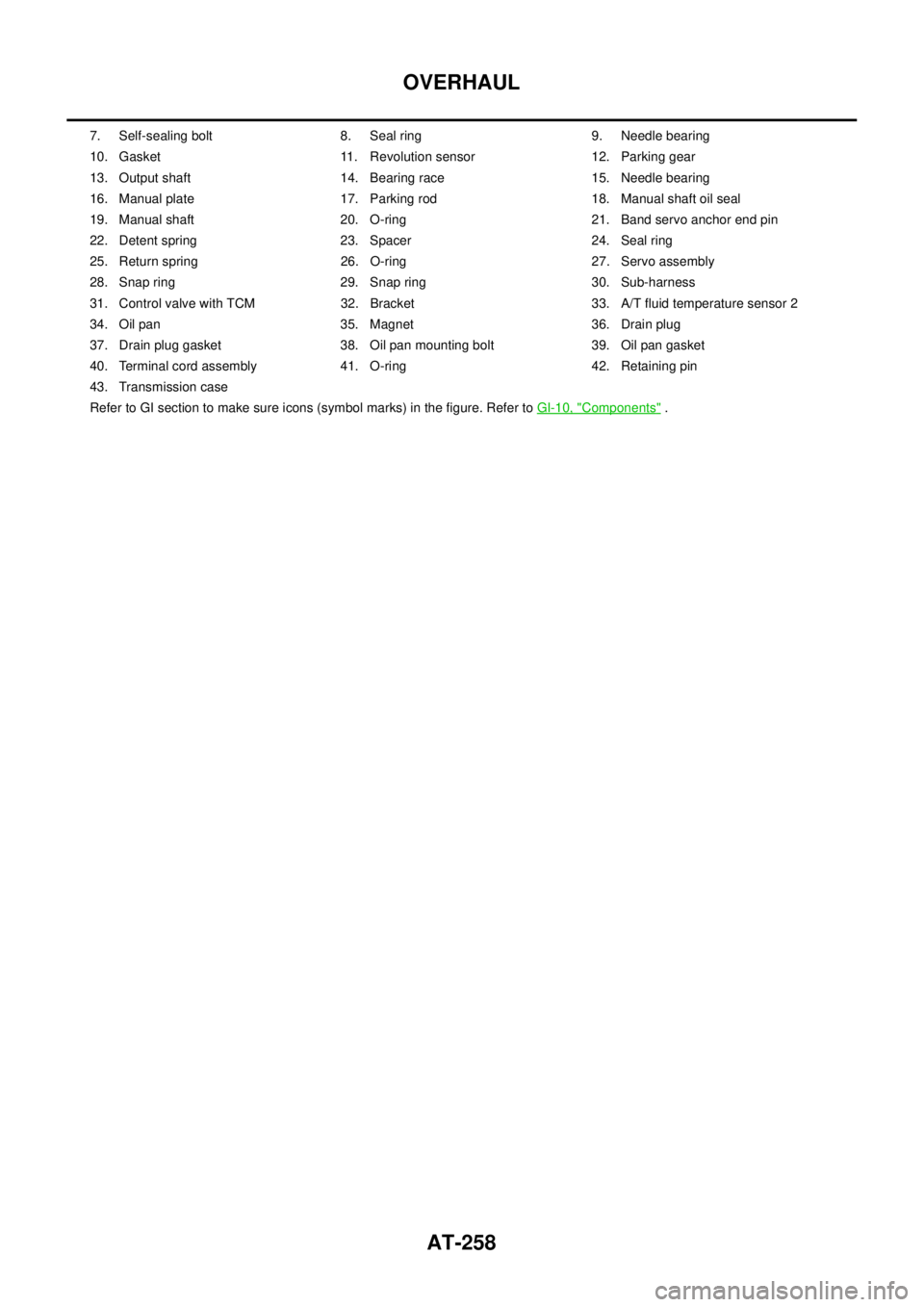
7. Self-sealing bolt 8. Seal ring 9. Needle bearing
10. Gasket 11. Revolution sensor 12. Parking gear
13. Output shaft 14. Bearing race 15. Needle bearing
16. Manual plate 17. Parking rod 18. Manual shaft oil seal
19. Manual shaft 20. O-ring 21. Band servo anchor end pin
22. Detent spring 23. Spacer 24. Seal ring
25. Return spring 26. O-ring 27. Servo assembly
28. Snap ring 29. Snap ring 30. Sub-harness
31. Control valve with TCM 32. Bracket 33. A/T fluid temperature sensor 2
34. Oil pan 35. Magnet 36. Drain plug
37. Drain plug gasket 38. Oil pan mounting bolt 39. Oil pan gasket
40. Terminal cord assembly 41. O-ring 42. Retaining pin
43. Transmission case
Refer to GI section to make sure icons (symbol marks) in the figure. Refer toGI-10, "
Components".
Page 278 of 3171
AT-270
DISASSEMBLY
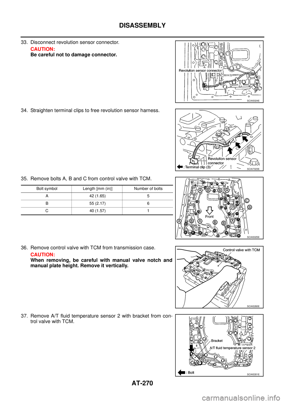
33. Disconnect revolution sensor connector.
CAUTION:
Be careful not to damage connector.
34. Straighten terminal clips to free revolution sensor harness.
35. Remove bolts A, B and C from control valve with TCM.
36. Remove control valve with TCM from transmission case.
CAUTION:
When removing, be careful with manual valve notch and
manual plate height. Remove it vertically.
37. Remove A/T fluid temperature sensor 2 with bracket from con-
trol valve with TCM.
SCIA5024E
SCIA7023E
Bolt symbol Length [mm (in)] Number of bolts
A 42 (1.65) 5
B 55 (2.17) 6
C 40 (1.57) 1
SCIA5025E
SCIA5260E
SCIA5301E
Page 327 of 3171
ASSEMBLY
AT-319
D
E
F
G
H
I
J
K
L
MA
B
AT
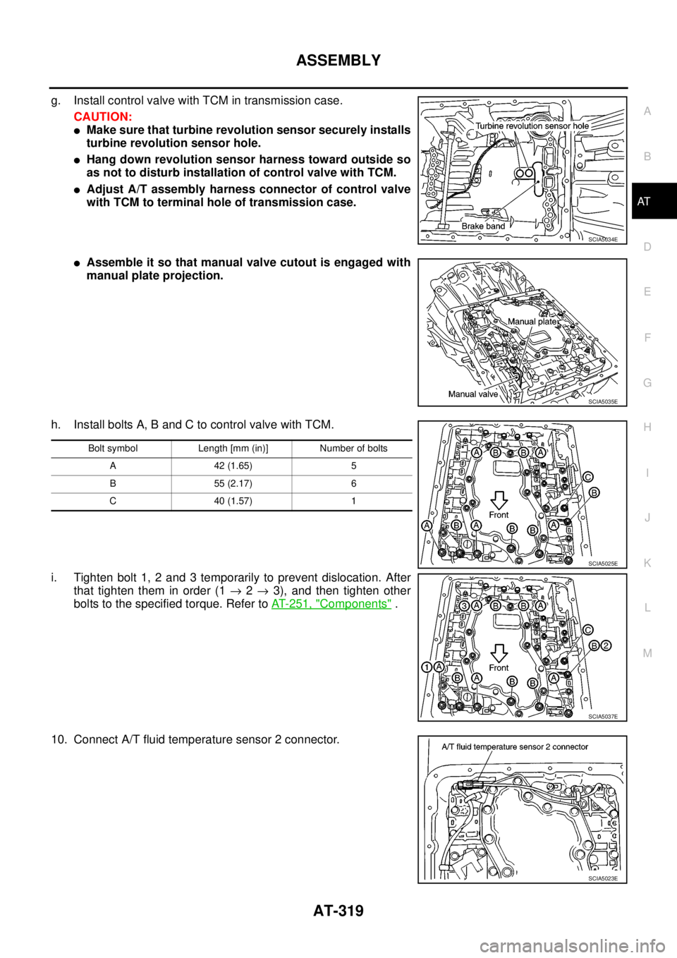
g. Install control valve with TCM in transmission case.
CAUTION:
lMake sure that turbine revolution sensor securely installs
turbine revolution sensor hole.
lHang down revolution sensor harness toward outside so
as not to disturb installation of control valve with TCM.
lAdjust A/T assembly harness connector of control valve
with TCM to terminal hole of transmission case.
lAssemble it so that manual valve cutout is engaged with
manual plate projection.
h. Install bolts A, B and C to control valve with TCM.
i. Tighten bolt 1, 2 and 3 temporarily to prevent dislocation. After
that tighten them in order (1®2®3), and then tighten other
bolts to the specified torque. Refer toAT- 2 5 1 , "
Components".
10. Connect A/T fluid temperature sensor 2 connector.
SCIA5034E
SCIA5035E
Bolt symbol Length [mm (in)] Number of bolts
A42(1.65) 5
B55(2.17) 6
C40(1.57) 1
SCIA5025E
SCIA5037E
SCIA5023E
Page 331 of 3171
SERVICE DATA AND SPECIFICATIONS (SDS)
AT-323
D
E
F
G
H
I
J
K
L
MA
B
AT
SERVICE DATA AND SPECIFICATIONS (SDS)PFP:00030
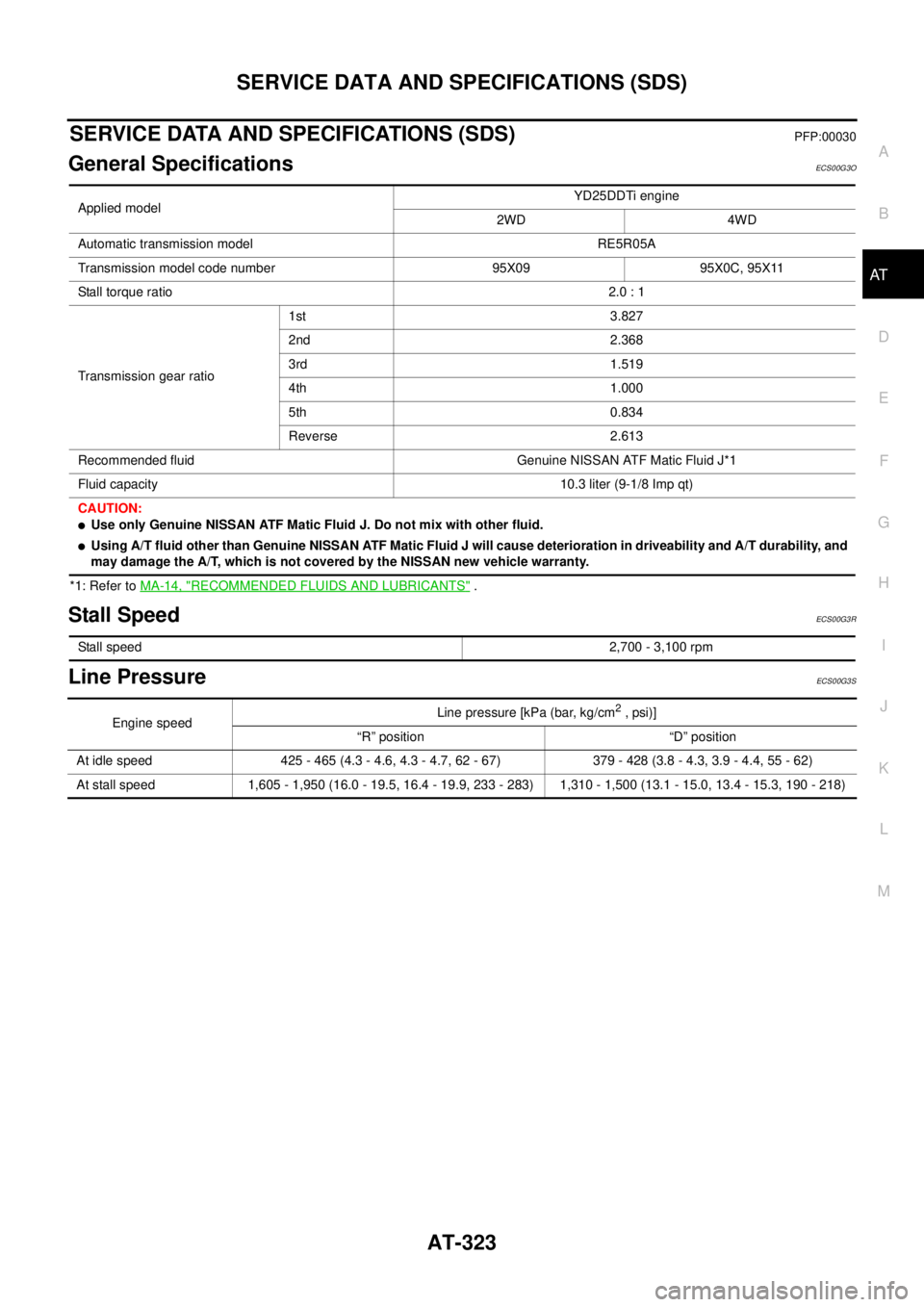
General SpecificationsECS00G3O
*1: Refer toMA-14, "RECOMMENDED FLUIDS AND LUBRICANTS".
Stall SpeedECS00G3R
Line PressureECS00G3S
Applied modelYD25DDTi engine
2WD 4WD
Automatic transmission model RE5R05A
Transmission model code number 95X09 95X0C, 95X11
Stall torque ratio2.0 : 1
Transmission gear ratio1st 3.827
2nd 2.368
3rd 1.519
4th 1.000
5th 0.834
Reverse 2.613
Recommended fluid Genuine NISSAN ATF Matic Fluid J*1
Fluid capacity 10.3 liter (9-1/8 Imp qt)
CAUTION:
lUse only Genuine NISSAN ATF Matic Fluid J. Do not mix with other fluid.
lUsing A/T fluid other than Genuine NISSAN ATF Matic Fluid J will cause deterioration in driveability and A/T durability, and
may damage the A/T, which is not covered by the NISSAN new vehicle warranty.
Stall speed2,700 - 3,100 rpm
Engine speedLine pressure [kPa (bar, kg/cm2,psi)]
“R” position “D” position
At idle speed 425 - 465 (4.3 - 4.6, 4.3 - 4.7, 62 - 67) 379 - 428 (3.8 - 4.3, 3.9 - 4.4, 55 - 62)
At stall speed 1,605 - 1,950 (16.0 - 19.5, 16.4 - 19.9, 233 - 283) 1,310 - 1,500 (13.1 - 15.0, 13.4 - 15.3, 190 - 218)
Page 865 of 3171
CL-1
CLUTCH
C TRANSMISSION/TRANSAXLE
CONTENTS
D
E
F
G
H
I
J
K
L
M
SECTIONCL
A
B
CL
CLUTCH
PRECAUTIONS .......................................................... 2
Service Notice or Precautions .................................. 2
PREPARATION ........................................................... 3
Special Service Tools ............................................... 3
Commercial Service Tools ........................................ 3
NOISE, VIBRATION AND HARSHNESS (NVH)
TROUBLESHOOTING ................................................ 5
NVH Troubleshooting Chart ..................................... 5
CLUTCH PEDAL ........................................................ 6
On-Vehicle Inspection and Adjustment .................... 6
Removal and Installation .......................................... 7
COMPONENTS .................................................... 7
REMOVAL ............................................................. 7
INSPECTION AFTER REMOVAL ......................... 7
INSTALLATION ..................................................... 7
CLUTCH FLUID .......................................................... 8
Air Bleeding Procedure ............................................ 8
CLUTCH MASTER CYLINDER .................................. 9
Components ............................................................. 9
Removal and Installation .......................................... 9
REMOVAL ............................................................. 9
INSTALLATION ..................................................... 9
Disassembly and Assembly ................................... 10
DISASSEMBLY ................................................... 10
INSPECTION AFTER DISASSEMBLY ............... 10
ASSEMBLY ......................................................... 10
OPERATING CYLINDER ...........................................11
Components ............................................................ 11
Removal and Installation ......................................... 11REMOVAL ........................................................... 11
INSTALLATION ................................................... 12
Disassembly and Assembly .................................... 12
DISASSEMBLY ................................................... 12
INSPECTION AFTER DISASSEMBLY ................ 12
ASSEMBLY ......................................................... 12
CLUTCH PIPING ....................................................... 13
Removal and Installation ........................................ 13
CLUTCH RELEASE MECHANISM ........................... 14
Removal and Installation ........................................ 14
COMPONENTS ................................................... 14
REMOVAL ........................................................... 14
INSPECTION AFTER REMOVAL ....................... 15
INSTALLATION ................................................... 15
CLUTCH DISC, CLUTCH COVER AND FLYWHEEL... 17
Removal and Installation ........................................ 17
COMPONENTS ................................................... 17
REMOVAL ........................................................... 17
INSPECTION AND ADJUSTMENT AFTER
REMOVAL ........................................................... 17
INSTALLATION ................................................... 18
SERVICE DATA AND SPECIFICATIONS (SDS) ...... 20
Clutch Control System ............................................ 20
Clutch Master Cylinder ........................................... 20
Clutch Operating Cylinder ...................................... 20
Clutch Disc ............................................................. 20
Clutch Cover ........................................................... 20
Clutch Pedal ........................................................... 20
Page 1447 of 3171
CAMSHAFT
EM-65
C
D
E
F
G
H
I
J
K
L
MA
EM
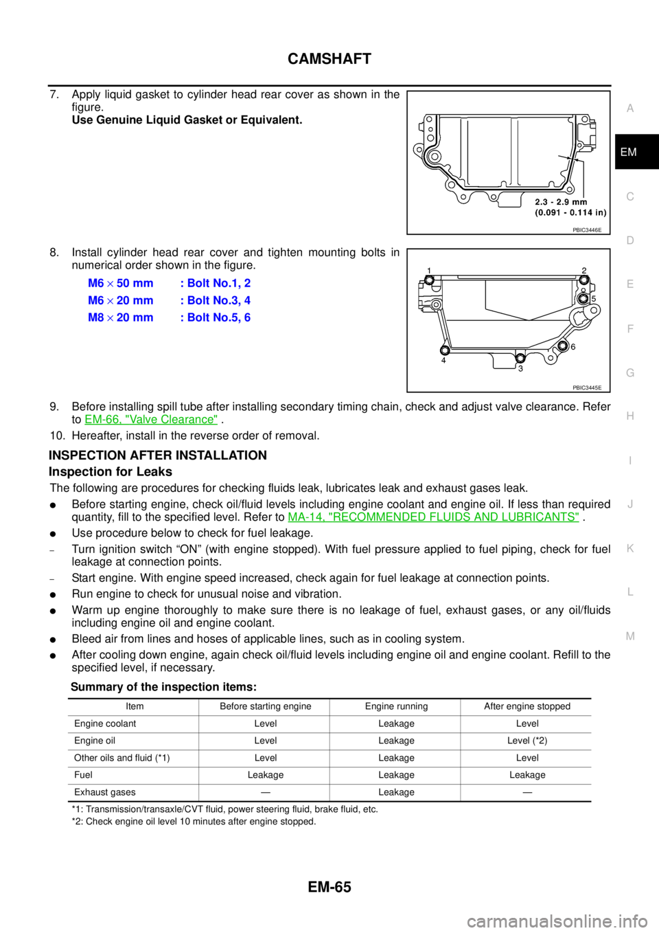
7. Apply liquid gasket to cylinder head rear cover as shown in the
figure.
Use Genuine Liquid Gasket or Equivalent.
8. Install cylinder head rear cover and tighten mounting bolts in
numerical order shown in the figure.
9. Before installing spill tube after installing secondary timing chain, check and adjust valve clearance. Refer
toEM-66, "
Valve Clearance".
10. Hereafter, install in the reverse order of removal.
INSPECTION AFTER INSTALLATION
Inspection for Leaks
The following are procedures for checking fluids leak, lubricates leak and exhaust gases leak.
lBefore starting engine, check oil/fluid levels including engine coolant and engine oil. If less than required
quantity, fill to the specified level. Refer toMA-14, "
RECOMMENDED FLUIDS AND LUBRICANTS".
lUse procedure below to check for fuel leakage.
–Turn ignition switch “ON” (with engine stopped). With fuel pressure applied to fuel piping, check for fuel
leakage at connection points.
–Start engine. With engine speed increased, check again for fuel leakage at connection points.
lRun engine to check for unusual noise and vibration.
lWarm up engine thoroughly to make sure there is no leakage of fuel, exhaust gases, or any oil/fluids
including engine oil and engine coolant.
lBleed air from lines and hoses of applicable lines, such as in cooling system.
lAfter cooling down engine, again check oil/fluid levels including engine oil and engine coolant. Refill to the
specified level, if necessary.
Summary of the inspection items:
*1: Transmission/transaxle/CVT fluid, power steering fluid, brake fluid, etc.
*2: Check engine oil level 10 minutes after engine stopped.
PBIC3446E
M6´50 mm : Bolt No.1, 2
M6´20 mm : Bolt No.3, 4
M8´20 mm : Bolt No.5, 6
PBIC3445E
Item Before starting engine Engine running After engine stopped
Engine coolant Level Leakage Level
Engine oil Level Leakage Level (*2)
Other oils and fluid (*1) Level Leakage Level
Fuel Leakage Leakage Leakage
Exhaust gases — Leakage —
Page 1460 of 3171

EM-78
SECONDARY TIMING CHAIN
Summary of the inspection items:
*1: Transmission/transaxle/CVT fluid, power steering fluid, brake fluid, etc.
*2: Check engine oil level 10 minutes after engine stopped.Item Before starting engine Engine running After engine stopped
Engine coolant Level Leakage Level
Engine oil Level Leakage Level (*2)
Other oils and fluid (*1) Level Leakage Level
Fuel Leakage Leakage Leakage
Exhaust gases — Leakage —
Page 1473 of 3171
PRIMARY TIMING CHAIN
EM-91
C
D
E
F
G
H
I
J
K
L
MA
EM
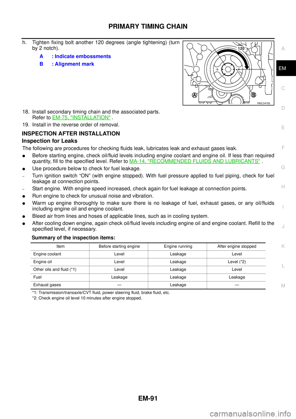
h. Tighten fixing bolt another 120 degrees (angle tightening) (turn
by 2 notch).
18. Install secondary timing chain and the associated parts.
Refer toEM-75, "
INSTALLATION".
19. Install in the reverse order of removal.
INSPECTION AFTER INSTALLATION
Inspection for Leaks
The following are procedures for checking fluids leak, lubricates leak and exhaust gases leak.
lBefore starting engine, check oil/fluid levels including engine coolant and engine oil. If less than required
quantity, fill to the specified level. Refer toMA-14, "
RECOMMENDED FLUIDS AND LUBRICANTS".
lUse procedure below to check for fuel leakage.
–Turn ignition switch “ON” (with engine stopped). With fuel pressure applied to fuel piping, check for fuel
leakage at connection points.
–Start engine. With engine speed increased, check again for fuel leakage at connection points.
lRun engine to check for unusual noise and vibration.
lWarm up engine thoroughly to make sure there is no leakage of fuel, exhaust gases, or any oil/fluids
including engine oil and engine coolant.
lBleed air from lines and hoses of applicable lines, such as in cooling system.
lAfter cooling down engine, again check oil/fluid levels including engine oil and engine coolant. Refill to the
specified level, if necessary.
Summary of the inspection items:
*1: Transmission/transaxle/CVT fluid, power steering fluid, brake fluid, etc.
*2: Check engine oil level 10 minutes after engine stopped.
A : Indicate embossments
B : Alignment mark
PBIC3476E
Item Before starting engine Engine running After engine stopped
Engine coolant Level Leakage Level
Engine oil Level Leakage Level (*2)
Other oils and fluid (*1) Level Leakage Level
Fuel Leakage Leakage Leakage
Exhaust gases — Leakage —