2005 NISSAN NAVARA transmission fluid
[x] Cancel search: transmission fluidPage 1480 of 3171
EM-98
CYLINDER HEAD
lBefore installing, remove carbon depositing on mounting hole of glow plug with a reamer.
6. Install engine coolant temperature sensor.
7. Install in the reverse order of removal.
INSPECTION AFTER INSTALLATION
Inspection for Leaks
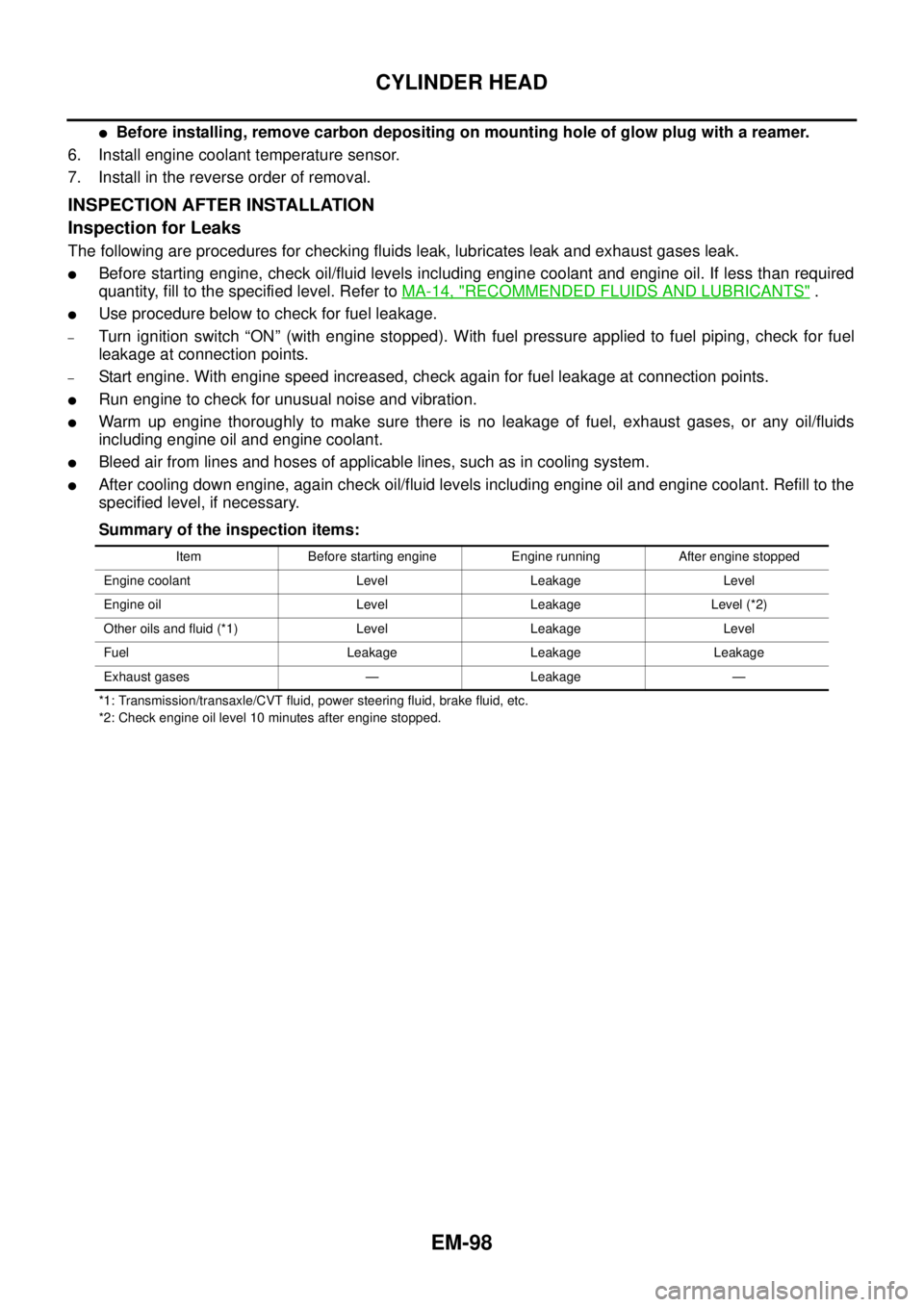
The following are procedures for checking fluids leak, lubricates leak and exhaust gases leak.
lBefore starting engine, check oil/fluid levels including engine coolant and engine oil. If less than required
quantity, fill to the specified level. Refer toMA-14, "
RECOMMENDED FLUIDS AND LUBRICANTS".
lUse procedure below to check for fuel leakage.
–Turn ignition switch “ON” (with engine stopped). With fuel pressure applied to fuel piping, check for fuel
leakage at connection points.
–Start engine. With engine speed increased, check again for fuel leakage at connection points.
lRun engine to check for unusual noise and vibration.
lWarm up engine thoroughly to make sure there is no leakage of fuel, exhaust gases, or any oil/fluids
including engine oil and engine coolant.
lBleed air from lines and hoses of applicable lines, such as in cooling system.
lAfter cooling down engine, again check oil/fluid levels including engine oil and engine coolant. Refill to the
specified level, if necessary.
Summary of the inspection items:
*1: Transmission/transaxle/CVT fluid, power steering fluid, brake fluid, etc.
*2: Check engine oil level 10 minutes after engine stopped.Item Before starting engine Engine running After engine stopped
Engine coolant Level Leakage Level
Engine oil Level Leakage Level (*2)
Other oils and fluid (*1) Level Leakage Level
Fuel Leakage Leakage Leakage
Exhaust gases — Leakage —
Page 1489 of 3171
ENGINE ASSEMBLY
EM-107
C
D
E
F
G
H
I
J
K
L
MA
EM
lFor supporting points for lifting and jacking point at rear axle, refer toGI-52, "Pantograph Jack,
Garage Jack and Safety Stand".
REMOVAL
Description of work
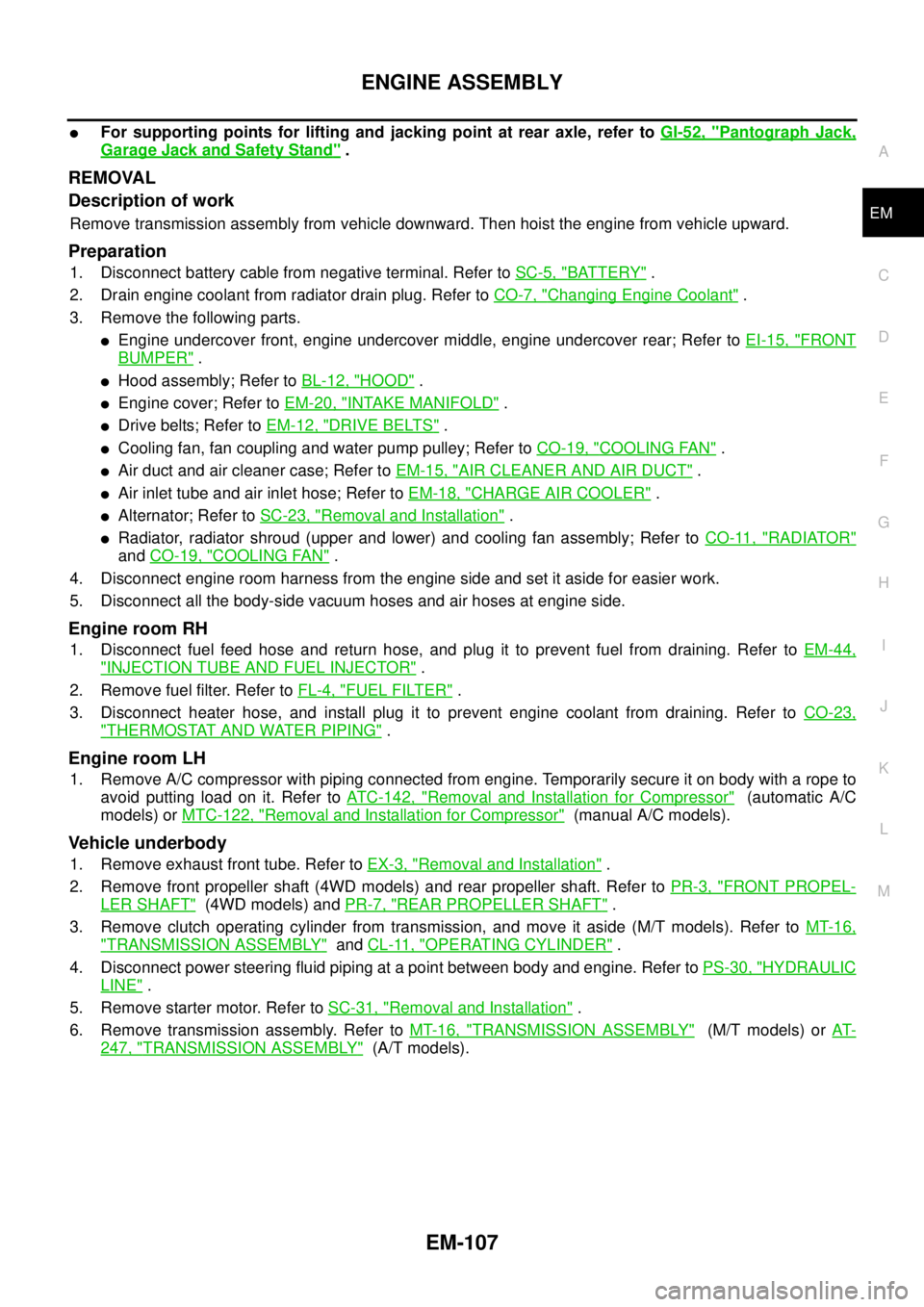
Remove transmission assembly from vehicle downward. Then hoist the engine from vehicle upward.
Preparation
1. Disconnect battery cable from negative terminal. Refer toSC-5, "BATTERY".
2. Drain engine coolant from radiator drain plug. Refer toCO-7, "
Changing Engine Coolant".
3. Remove the following parts.
lEngine undercover front, engine undercover middle, engine undercover rear; Refer toEI-15, "FRONT
BUMPER".
lHood assembly; Refer toBL-12, "HOOD".
lEngine cover; Refer toEM-20, "INTAKE MANIFOLD".
lDrive belts; Refer toEM-12, "DRIVE BELTS".
lCooling fan, fan coupling and water pump pulley; Refer toCO-19, "COOLING FAN".
lAir duct and air cleaner case; Refer toEM-15, "AIR CLEANER AND AIR DUCT".
lAir inlet tube and air inlet hose; Refer toEM-18, "CHARGE AIR COOLER".
lAlternator; Refer toSC-23, "Removal and Installation".
lRadiator, radiator shroud (upper and lower) and cooling fan assembly; Refer toCO-11, "RADIATOR"
andCO-19, "COOLING FAN".
4. Disconnect engine room harness from the engine side and set it aside for easier work.
5. Disconnect all the body-side vacuum hoses and air hoses at engine side.
Engine room RH
1. Disconnect fuel feed hose and return hose, and plug it to prevent fuel from draining. Refer toEM-44,
"INJECTION TUBE AND FUEL INJECTOR".
2. Remove fuel filter. Refer toFL-4, "
FUEL FILTER".
3. Disconnect heater hose, and install plug it to prevent engine coolant from draining. Refer toCO-23,
"THERMOSTAT AND WATER PIPING".
Engine room LH
1. Remove A/C compressor with piping connected from engine. Temporarily secure it on body with a rope to
avoid putting load on it. Refer toATC-142, "
Removal and Installation for Compressor"(automatic A/C
models) orMTC-122, "
Removal and Installation for Compressor"(manual A/C models).
Vehicle underbody
1. Remove exhaust front tube. Refer toEX-3, "Removal and Installation".
2. Remove front propeller shaft (4WD models) and rear propeller shaft. Refer toPR-3, "
FRONT PROPEL-
LER SHAFT"(4WD models) andPR-7, "REAR PROPELLER SHAFT".
3. Remove clutch operating cylinder from transmission, and move it aside (M/T models). Refer toMT-16,
"TRANSMISSION ASSEMBLY"andCL-11, "OPERATING CYLINDER".
4. Disconnect power steering fluid piping at a point between body and engine. Refer toPS-30, "
HYDRAULIC
LINE".
5. Remove starter motor. Refer toSC-31, "
Removal and Installation".
6. Remove transmission assembly. Refer toMT-16, "
TRANSMISSION ASSEMBLY"(M/T models) orAT-
247, "TRANSMISSION ASSEMBLY"(A/T models).
Page 1491 of 3171
ENGINE ASSEMBLY
EM-109
C
D
E
F
G
H
I
J
K
L
MA
EM
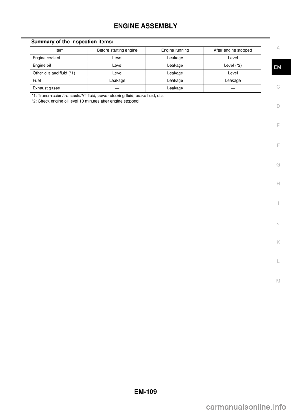
Summary of the inspection items:
*1: Transmission/transaxle/AT fluid, power steering fluid, brake fluid, etc.
*2: Check engine oil level 10 minutes after engine stopped.Item Before starting engine Engine running After engine stopped
Engine coolant Level Leakage Level
Engine oil Level Leakage Level (*2)
Other oils and fluid (*1) Level Leakage Level
Fuel Leakage Leakage Leakage
Exhaust gases — Leakage —
Page 1627 of 3171
PRECAUTIONS
GI-5
C
D
E
F
G
H
I
J
K
L
MB
GI
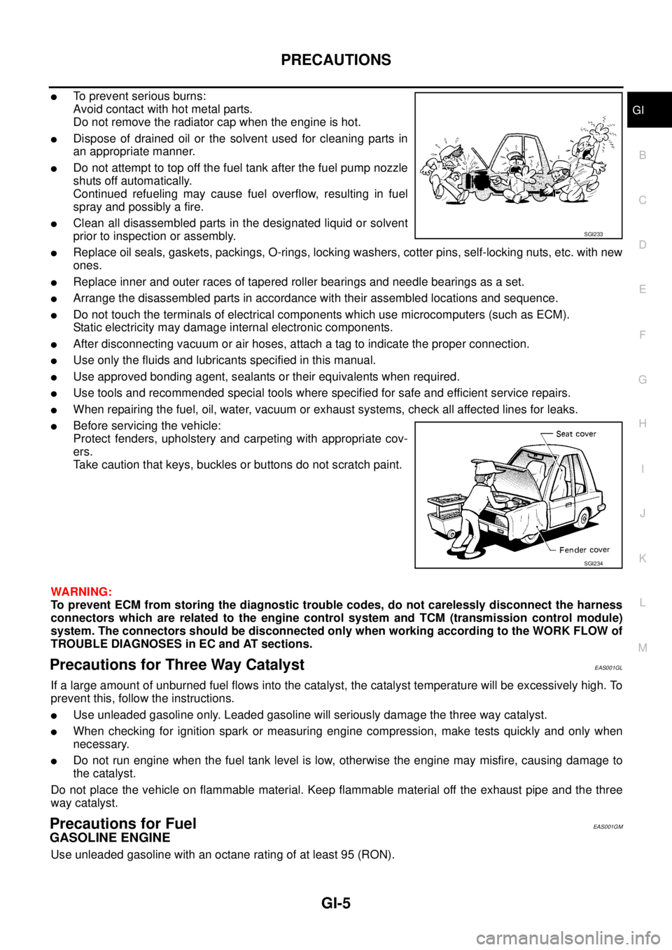
lTo prevent serious burns:
Avoid contact with hot metal parts.
Do not remove the radiator cap when the engine is hot.
lDispose of drained oil or the solvent used for cleaning parts in
an appropriate manner.
lDo not attempt to top off the fuel tank after the fuel pump nozzle
shuts off automatically.
Continued refueling may cause fuel overflow, resulting in fuel
spray and possibly a fire.
lClean all disassembled parts in the designated liquid or solvent
prior to inspection or assembly.
lReplace oil seals, gaskets, packings, O-rings, locking washers, cotter pins, self-locking nuts, etc. with new
ones.
lReplace inner and outer races of tapered roller bearings and needle bearings as a set.
lArrange the disassembled parts in accordance with their assembled locations and sequence.
lDo not touch the terminals of electrical components which use microcomputers (such as ECM).
Static electricity may damage internal electronic components.
lAfter disconnecting vacuum or air hoses, attach a tag to indicate the proper connection.
lUse only the fluids and lubricants specified in this manual.
lUse approved bonding agent, sealants or their equivalents when required.
lUse tools and recommended special tools where specified for safe and efficient service repairs.
lWhen repairing the fuel, oil, water, vacuum or exhaust systems, check all affected lines for leaks.
lBefore servicing the vehicle:
Protect fenders, upholstery and carpeting with appropriate cov-
ers.
Take caution that keys, buckles or buttons do not scratch paint.
WARNING:
To prevent ECM from storing the diagnostic trouble codes, do not carelessly disconnect the harness
connectors which are related to the engine control system and TCM (transmission control module)
system. The connectors should be disconnected only when working according to the WORK FLOW of
TROUBLE DIAGNOSES in EC and AT sections.
Precautions for Three Way CatalystEAS001GL
If a large amount of unburned fuel flows into the catalyst, the catalyst temperature will be excessively high. To
prevent this, follow the instructions.
lUse unleaded gasoline only. Leaded gasoline will seriously damage the three way catalyst.
lWhen checking for ignition spark or measuring engine compression, make tests quickly and only when
necessary.
lDo not run engine when the fuel tank level is low, otherwise the engine may misfire, causing damage to
the catalyst.
Do not place the vehicle on flammable material. Keep flammable material off the exhaust pipe and the three
way catalyst.
Precautions for FuelEAS001GM
GASOLINE ENGINE
Use unleaded gasoline with an octane rating of at least 95 (RON).
SGI233
SGI234
Page 1645 of 3171
HOW TO USE THIS MANUAL
GI-23
C
D
E
F
G
H
I
J
K
L
MB
GI
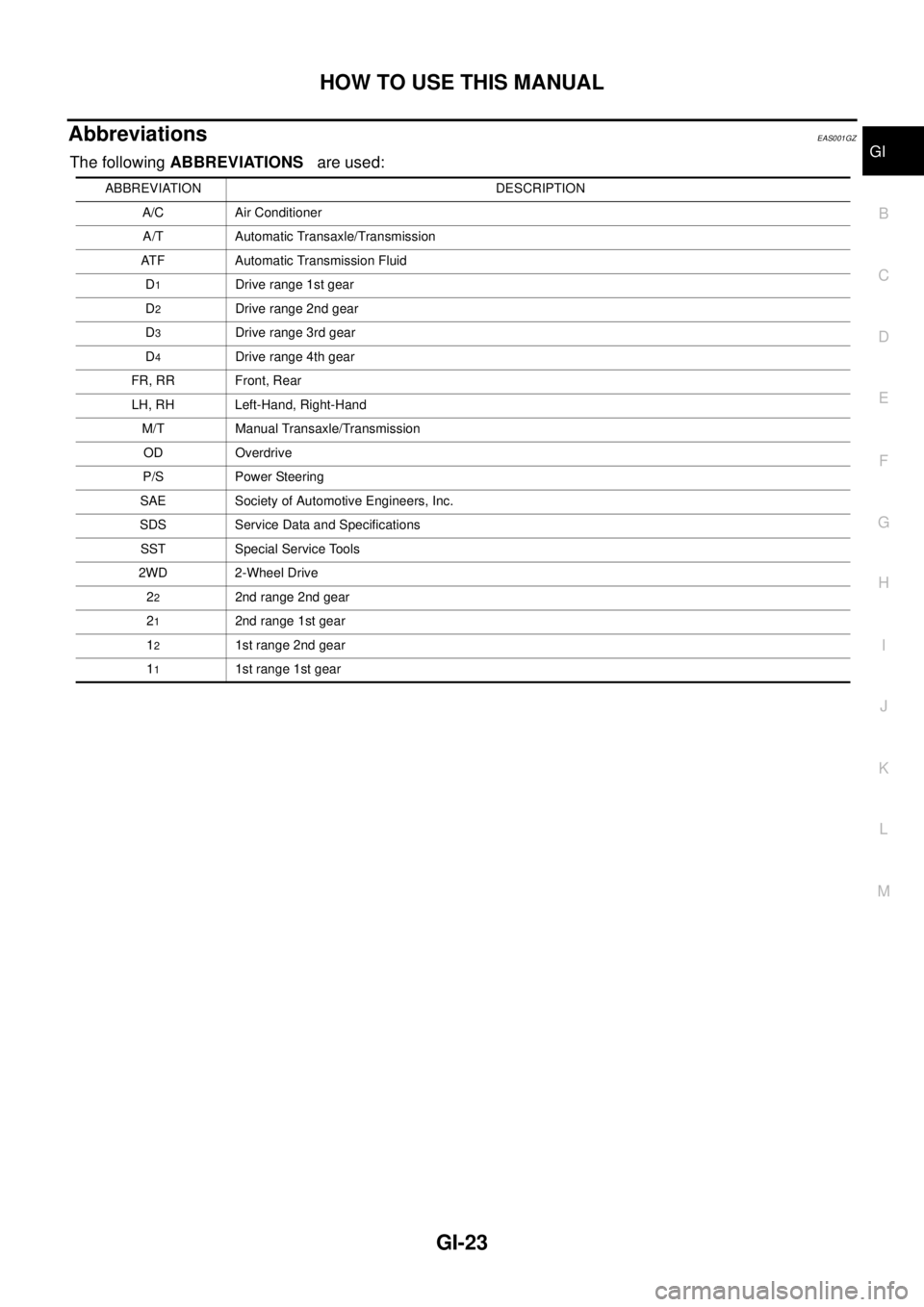
AbbreviationsEAS001GZ
The followingABBREVIATIONSare used:
ABBREVIATION DESCRIPTION
A/C Air Conditioner
A/T Automatic Transaxle/Transmission
ATF Automatic Transmission Fluid
D
1Drive range 1st gear
D
2Drive range 2nd gear
D
3Drive range 3rd gear
D
4Drive range 4th gear
FR, RR Front, Rear
LH, RH Left-Hand, Right-Hand
M/T Manual Transaxle/Transmission
OD Overdrive
P/S Power Steering
SAE Society of Automotive Engineers, Inc.
SDS Service Data and Specifications
SST Special Service Tools
2WD 2-Wheel Drive
2
22nd range 2nd gear
2
12nd range 1st gear
1
21st range 2nd gear
1
11st range 1st gear
Page 1754 of 3171
IDX-2
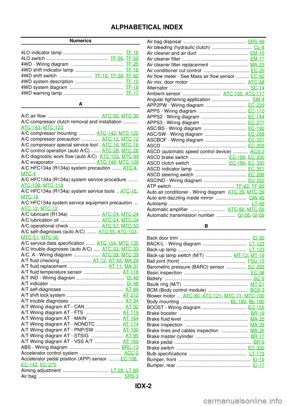
ALPHABETICAL INDEX
Numerics
4LO indicator lamp .............................................TF-16
4LO switch ..............................................TF-56,TF-59
4WD - Wiring diagram .......................................TF-25
4WD shift indicator lamp ....................................TF-16
4WD shift switch .........................TF-16,TF-59,TF-62
4WD system description ....................................TF-15
4WD system diagram ........................................TF-18
4WD warning lamp ............................................TF-17
A
A/C air flow .......................................ATC-30
,MTC-30
A/C compressor clutch removal and installation ...........
ATC-143
,MTC-123
A/C compressor mounting ............ATC-142,MTC-122
A/C compressor precaution ..............ATC-12,MTC-12
A/C compressor special service tool .ATC-16,MTC-16
A/C control operation (auto A/C) .......ATC-28,MTC-28
A/C diagnostic work flow (auto A/C)ATC-103,MTC-95
A/C evaporator ..............................ATC-149,MTC-129
A/C HFC134a (R134a) system precaution .......ATC-4,
MTC-4
A/C HFC134a (R134a) system service procedure .......
ATC-138
,MTC-118
A/C HFC134a (R134a) system service tools ..ATC-16,
MTC-16
A/C HFC134a system service equipment precaution ...
ATC-12
,MTC-12
A/C lubricant (R134a) .......................ATC-24,MTC-24
A/C lubrication oil ..............................ATC-24,MTC-24
A/C operational check .......................ATC-57,MTC-53
A/C self-diagnoses (auto A/C) .......ATC-55,ATC-103,
MTC-51
,MTC-95
A/C service data specification .......ATC-154,MTC-135
A/C trouble diagnoses (auto A/C) .....ATC-33,MTC-33
A/C, A - Wiring diagram ....................ATC-39,MTC-39
A/T fluid checking ......................AT-12,AT-43,MA-29
A/T fluid replacement .............................AT-11,MA-31
A/T fluid temperature sensor ...........................AT-118
A/T IND - Wiring diagram ....................................DI-49
A/T indicator ........................................................DI-48
A/T self-diagnoses .............................................AT-89
A/T shift lock system ........................................AT-212
A/T trouble diagnoses ........................................AT-34
A/T Wiring diagram AT - CAN ............................AT-92
A/T Wiring diagram AT - FTS ..........................AT-119
A/T Wiring diagram AT - MAIN ........................AT-164
A/T Wiring diagram AT - NONDTC ..................AT-174
A/T Wiring diagram AT - PNP/SW ...................AT-100
A/T Wiring diagram AT - STSIG ........................AT-95
A/T Wiring diagram AT - VSS A/T ...................AT-105
ABS - Wiring diagram .....................................BRC-13
Accelerator control system ...............................ACC-2
Accelerator pedal position (APP) sensor ........EC-108,
EC-142
,EC-275
Aiming adjustment ..................................LT-28,LT-85
Air bag ..............................................................SRS-3
Air bag disposal ..............................................SRS-49
Air bleeding (hydraulic clutch) ..............................CL-8
Air cleaner and air duct .....................................EM-15
Air cleaner filter .................................................EM-17
Air cleaner filter replacement ............................MA-25
Air conditioner cut control ..................................EC-20
Air flow meter - See Mass air flow sensor ..........EC-92
Air mix. door motor .........................................ATC-68
Alternator ...........................................................SC-14
Ambient sensor .............................ATC-105,ATC-117
Angular tightening application .............................EM-4
APP2PW - Wiring diagram ..............................EC-229
APPS - Wiring diagram ....................................EC-110
APPS2 - Wiring diagram ..................................EC-144
APPS3 - Wiring diagram ..................................EC-277
ASC/BS - Wiring diagram ................................EC-192
ASC/SW - Wiring diagram ...............................EC-208
ASCBOF - Wiring diagram ...............................EC-331
ASCD ...............................................................EC-355
ASCD (automatic speed control device) ...........ACS-2
ASCD brake switch ...........................EC-189,EC-330
ASCD clutch switch ..........................EC-189,EC-330
ASCD indicator lamp .......................................EC-351
ASCD steering switch ......................................EC-206
ASCIND - Wiring diagram ................................EC-352
ATP switch ..............................................TF-82,TF-85
Auto air conditioner - Wiring diagramATC-39,MTC-39
Auto anti-dazzling inside mirror .......................GW-45
Autolamp ............................................................LT-49
Automatic amplifier ..........................ATC-60,MTC-55
Automatic transmission number ..............GI-58,GI-59
B
Back door trim .....................................................EI-30
BACK/L - Wiring diagram .................................LT-123
Back-up lamp ...................................................LT-123
Back-up lamp switch (M/T) ...................MT-12,MT-19
Ball joint (front) ................................................FSU-15
Barometric pressure (BARO) sensor ...............EC-293
Basic inspection .................................................EC-38
Battery .................................................................SC-5
Baulk ring (M/T) ................................................MT-21
BCM (Body control module) ..............................BCS-3
Blower motor ...ATC-80,ATC-121,MTC-71,MTC-100
Body mounting ....................................BL-189,BL-190
BOOST - Wiring diagram .................................EC-155
Brake booster ....................................................BR-19
Brake fluid level ................................................MA-35
Brake inspection ...............................................MA-35
Brake lines and cables inspection ....................MA-35
Brake master cylinder ........................................BR-17
Brake pedal ..........................................................BR-6
Brake switch ....................................................EC-330
Bulb specifications ...........................................LT-173
Bumper, front ......................................................EI-15
Bumper, rear .......................................................EI-17
Page 2280 of 3171
DESCRIPTION
MA-5
C
D
E
F
G
H
I
J
K
MA
B
MA
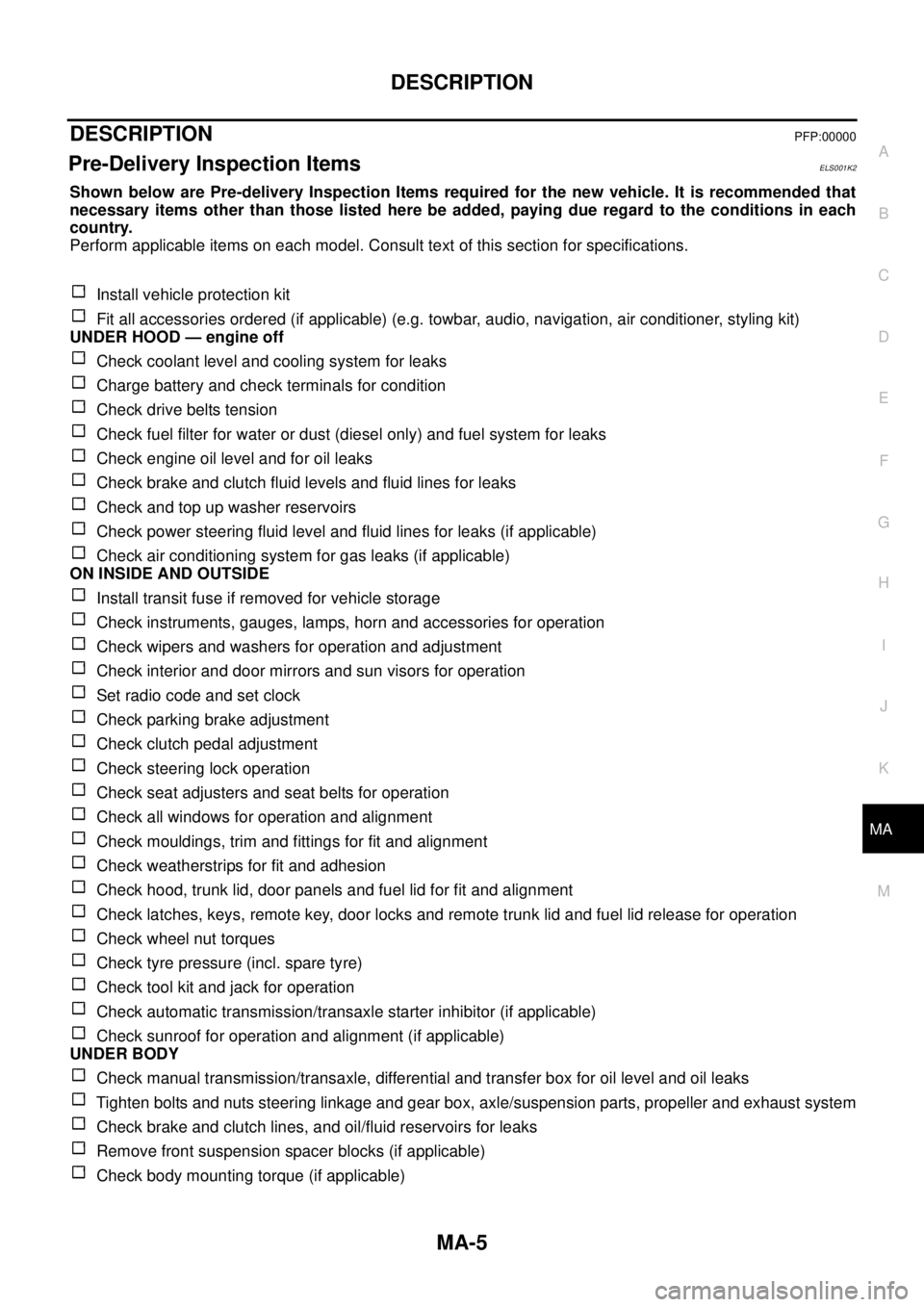
DESCRIPTIONPFP:00000
Pre-Delivery Inspection ItemsELS001K2
Shown below are Pre-delivery Inspection Items required for the new vehicle. It is recommended that
necessary items other than those listed here be added, paying due regard to the conditions in each
country.
Perform applicable items on each model. Consult text of this section for specifications.
Install vehicle protection kit
Fit all accessories ordered (if applicable) (e.g. towbar, audio, navigation, air conditioner, styling kit)
UNDER HOOD — engine off
Check coolant level and cooling system for leaks
Charge battery and check terminals for condition
Check drive belts tension
Check fuel filter for water or dust (diesel only) and fuel system for leaks
Check engine oil level and for oil leaks
Check brake and clutch fluid levels and fluid lines for leaks
Check and top up washer reservoirs
Check power steering fluid level and fluid lines for leaks (if applicable)
Check air conditioning system for gas leaks (if applicable)
ON INSIDE AND OUTSIDE
Install transit fuse if removed for vehicle storage
Check instruments, gauges, lamps, horn and accessories for operation
Check wipers and washers for operation and adjustment
Check interior and door mirrors and sun visors for operation
Set radio code and set clock
Check parking brake adjustment
Check clutch pedal adjustment
Check steering lock operation
Check seat adjusters and seat belts for operation
Check all windows for operation and alignment
Check mouldings, trim and fittings for fit and alignment
Check weatherstrips for fit and adhesion
Check hood, trunk lid, door panels and fuel lid for fit and alignment
Check latches, keys, remote key, door locks and remote trunk lid and fuel lid release for operation
Check wheel nut torques
Check tyre pressure (incl. spare tyre)
Check tool kit and jack for operation
Check automatic transmission/transaxle starter inhibitor (if applicable)
Check sunroof for operation and alignment (if applicable)
UNDER BODY
Check manual transmission/transaxle, differential and transfer box for oil level and oil leaks
Tighten bolts and nuts steering linkage and gear box, axle/suspension parts, propeller and exhaust system
Check brake and clutch lines, and oil/fluid reservoirs for leaks
Remove front suspension spacer blocks (if applicable)
Check body mounting torque (if applicable)
Page 2284 of 3171
PERIODIC MAINTENANCE
MA-9
C
D
E
F
G
H
I
J
K
MA
B
MA
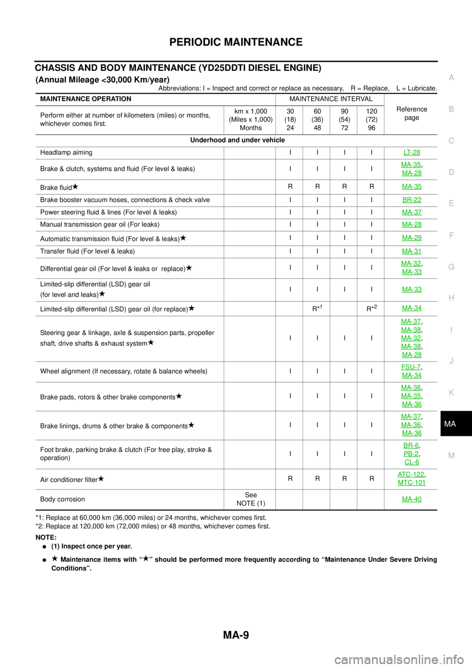
CHASSIS AND BODY MAINTENANCE (YD25DDTI DIESEL ENGINE)
(Annual Mileage <30,000 Km/year)
Abbreviations: I = Inspect and correct or replace as necessary, R = Replace, L = Lubricate.
*1: Replace at 60,000 km (36,000 miles) or 24 months, whichever comes first.
*2: Replace at 120,000 km (72,000 miles) or 48 months, whichever comes first.
NOTE:
l(1) Inspect once per year.
lMaintenance items with “ ” should be performed more frequently according to “Maintenance Under Severe Driving
Conditions”. MAINTENANCE OPERATIONMAINTENANCE INTERVAL
Reference
page Perform either at number of kilometers (miles) or months,
whichever comes first.km x 1,000
(Miles x 1,000)
Months30
(18)
2460
(36)
4890
(54)
72120
(72)
96
Underhood and under vehicle
Headlampaiming IIIILT- 2 8
Brake&clutch,systemsandfluid(Forlevel&leaks) IIIIMA-35,
MA-28
Brake fluidRRRRMA-35
Brakeboostervacuumhoses,connections&checkvalve IIIIBR-22
Powersteeringfluid&lines(Forlevel&leaks) IIIIMA-37
Manual transmission gear oil (For leaks)IIIIMA-28
Automatic transmission fluid (For level & leaks)IIIIMA-29
Transferfluid(Forlevel&leaks) IIIIMA-31
Differential gear oil (For level & leaks or replace)IIIIMA-32,
MA-33
Limited-slip differential (LSD) gear oil
(for level and leaks)IIIIMA-33
Limited-slip differential (LSD) gear oil (for replace)R*1R*2MA-34
Steering gear & linkage, axle & suspension parts, propeller
shaft, drive shafts & exhaust systemIIIIMA-37
,
MA-38
,
MA-32
,
MA-38
,
MA-28
Wheelalignment(Ifnecessary,rotate&balancewheels) IIIIFSU-7,
MA-34
Brake pads, rotors & other brake componentsIIIIMA-36
,
MA-35
,
MA-36
Brake linings, drums & other brake & componentsIIIIMA-37
,
MA-36
,
MA-36
Foot brake, parking brake & clutch (For free play, stroke &
operation)IIIIBR-6,
PB-2
,
CL-6
Air conditioner filterRRRRATC-122,
MTC-101
Body corrosionSee
NOTE (1)MA-40