2005 NISSAN NAVARA engine
[x] Cancel search: enginePage 1069 of 3171
DTC P0093 FUEL SYSTEM
EC-89
C
D
E
F
G
H
I
J
K
L
MA
EC
Diagnostic ProcedureEBS01KDS
1.PERFORM FUEL PUMP LEARNING VALUE CLEARING
NOTE:
If the DTC is detected because of air mixed with fuel (i.e.: caused by lack of fuel), it may become normal by
performing following procedure.
With CONSULT-II
1. Turn ignition switch ON.
2. Perform Fuel Pump Learning Value Clearing. Refer toEC-24, "
Fuel Pump Learning Value Clearing".
3. Start engine and let it idle for at least 60 seconds.
4. Select “SELF-DIAG RESULT” mode with CONSULT-II.
5. Touch “ERASE”.
6. PerformEC-88, "
DTC Confirmation Procedure",again.
7. Is DTC detected again?
Without CONSULT-II
1. Turn ignition switch ON.
2. Perform Fuel Pump Learning Value Clearing. Refer toEC-24, "
Fuel Pump Learning Value Clearing".
3. Start engine and let it idle for at least 60 seconds.
4. Erase the Diagnostic Test Mode II (Self-diagnostic results) memory. Refer toEC-27
.
5. PerformEC-88, "
DTC Confirmation Procedure",again.
6. Is DTC detected again?
Ye s o r N o
Ye s > > G O T O 2 .
No >>INSPECTION END
2.CHECK FUEL LINE FOR LEAK
1. Start engine.
2. Visually check the following for fuel leak.
–Fuel tube from fuel pump to fuel rail
–Fuel rail
–Fuel tube from fuel rail to fuel injector
3. Also check for improper connection or pinches.
OK or NG
OK >> GO TO 3.
NG >> Repair malfunctioning part.
3.CHECK FUEL RAIL PRESSURE RELIEF VALVE
Refer toEC-90, "
Component Inspection".
OK or NG
OK >> GO TO 4.
NG >> Replace fuel rail.
4.CHECK INTERMITTENT INCIDENT
Refer toEC-70, "
TROUBLE DIAGNOSIS FOR INTERMITTENT INCIDENT".
OK or NG
OK >> GO TO 5.
NG >> Repair or replace.
Page 1070 of 3171
EC-90
DTC P0093 FUEL SYSTEM
5.REPLACE FUEL PUMP
1. Replace fuel pump.
2. Perform Fuel Pump Learning Value Clearing. Refer toEC-24, "
Fuel Pump Learning Value Clearing".
>>INSPECTION END
Component InspectionEBS01KDT
FUEL RAIL PRESSURE RELIEF VALVE
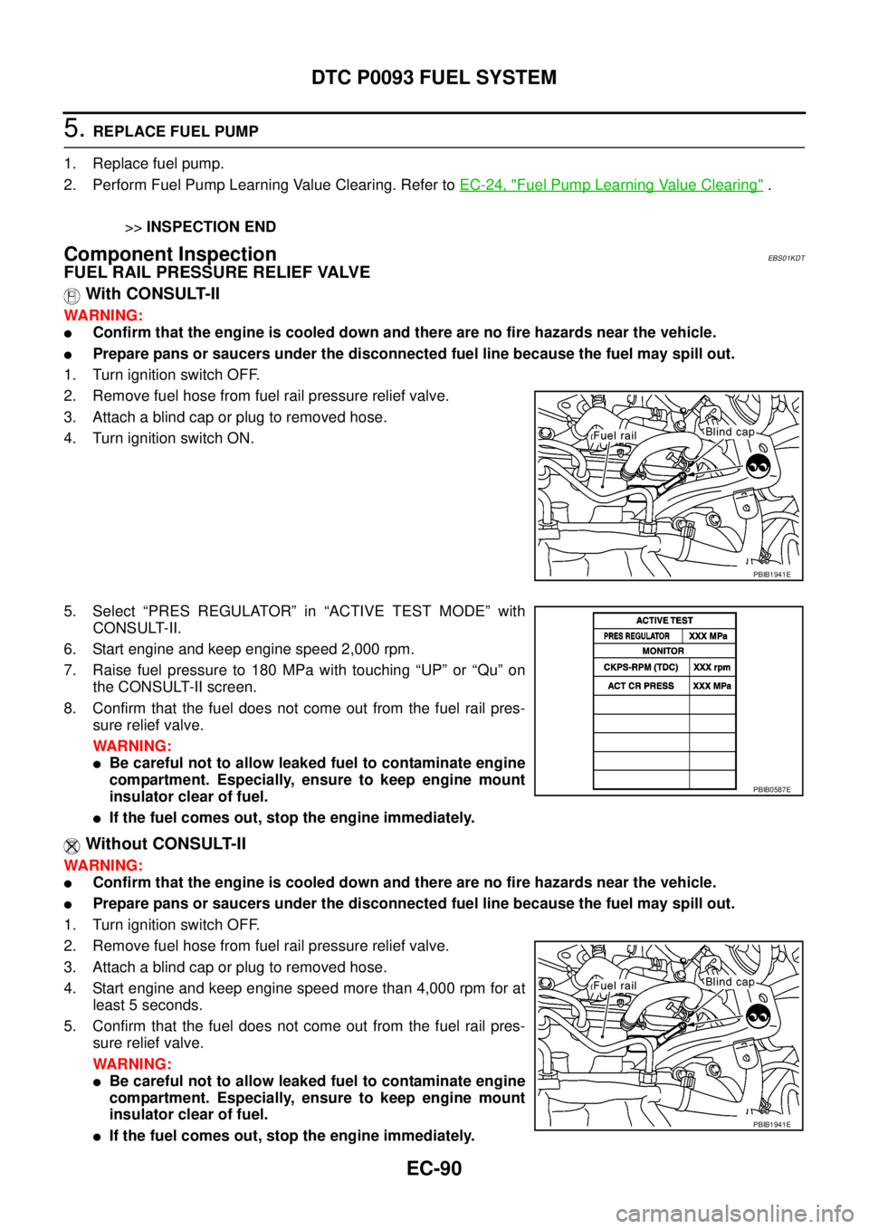
With CONSULT-II
WARNING:
lConfirm that the engine is cooled down and there are no fire hazards near the vehicle.
lPrepare pans or saucers under the disconnected fuel line because the fuel may spill out.
1. Turn ignition switch OFF.
2. Remove fuel hose from fuel rail pressure relief valve.
3. Attach a blind cap or plug to removed hose.
4. Turn ignition switch ON.
5. Select “PRES REGULATOR” in “ACTIVE TEST MODE” with
CONSULT-II.
6. Start engine and keep engine speed 2,000 rpm.
7. Raisefuelpressureto180MPawithtouching“UP”or“Qu”on
the CONSULT-II screen.
8. Confirm that the fuel does not come out from the fuel rail pres-
sure relief valve.
WARNING:
lBe careful not to allow leaked fuel to contaminate engine
compartment. Especially, ensure to keep engine mount
insulator clear of fuel.
lIf the fuel comes out, stop the engine immediately.
Without CONSULT-II
WARNING:
lConfirm that the engine is cooled down and there are no fire hazards near the vehicle.
lPrepare pans or saucers under the disconnected fuel line because the fuel may spill out.
1. Turn ignition switch OFF.
2. Remove fuel hose from fuel rail pressure relief valve.
3. Attach a blind cap or plug to removed hose.
4. Start engine and keep engine speed more than 4,000 rpm for at
least 5 seconds.
5. Confirm that the fuel does not come out from the fuel rail pres-
sure relief valve.
WARNING:
lBe careful not to allow leaked fuel to contaminate engine
compartment. Especially, ensure to keep engine mount
insulator clear of fuel.
lIf the fuel comes out, stop the engine immediately.
PBIB1941E
PBIB0587E
PBIB1941E
Page 1072 of 3171
EC-92
DTC P0102, P0103 MAF SENSOR
DTC P0102, P0103 MAF SENSOR
PFP:22680
Component DescriptionEBS01KDV
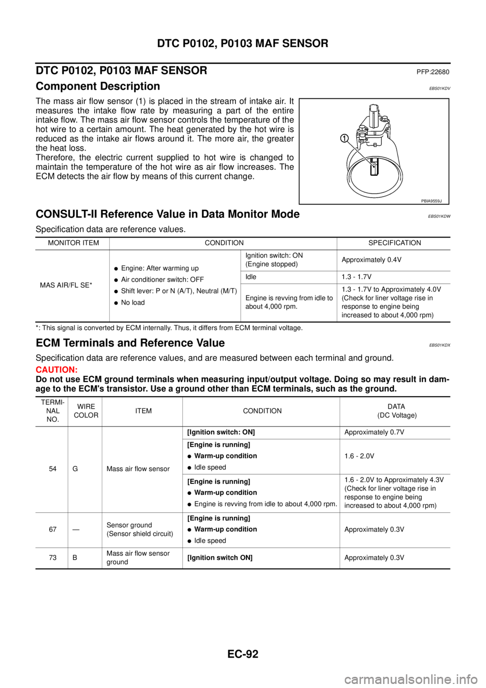
The mass air flow sensor (1) is placed in the stream of intake air. It
measures the intake flow rate by measuring a part of the entire
intake flow. The mass air flow sensor controls the temperature of the
hot wire to a certain amount. The heat generated by the hot wire is
reduced as the intake air flows around it. The more air, the greater
the heat loss.
Therefore, the electric current supplied to hot wire is changed to
maintain the temperature of the hot wire as air flow increases. The
ECM detects the air flow by means of this current change.
CONSULT-II Reference Value in Data Monitor ModeEBS01KDW
Specification data are reference values.
*: This signal is converted by ECM internally. Thus, it differs from ECM terminal voltage.
ECM Terminals and Reference ValueEBS01KDX
Specification data are reference values, and are measured between each terminal and ground.
CAUTION:
Do not use ECM ground terminals when measuring input/output voltage. Doing so may result in dam-
age to the ECM's transistor. Use a ground other than ECM terminals, such as the ground.
PBIA9559J
MONITOR ITEM CONDITION SPECIFICATION
MAS AIR/FL SE*
lEngine: After warming up
lAir conditioner switch: OFF
lShift lever: P or N (A/T), Neutral (M/T)
lNo loadIgnition switch: ON
(Engine stopped)Approximately 0.4V
Idle 1.3 - 1.7V
Engine is revving from idle to
about 4,000 rpm.1.3 - 1.7V to Approximately 4.0V
(Check for liner voltage rise in
response to engine being
increased to about 4,000 rpm)
TERMI-
NAL
NO.WIRE
COLORITEM CONDITIONDATA
(DC Voltage)
54 G Mass air flow sensor[Ignition switch: ON]Approximately 0.7V
[Engine is running]
lWarm-up condition
lIdle speed1.6 - 2.0V
[Engine is running]
lWarm-up condition
lEngine is revving from idle to about 4,000 rpm.1.6 - 2.0V to Approximately 4.3V
(Check for liner voltage rise in
response to engine being
increased to about 4,000 rpm)
67 —Sensor ground
(Sensor shield circuit)[Engine is running]
lWarm-up condition
lIdle speedApproximately 0.3V
73 BMass air flow sensor
ground[Ignition switch ON]Approximately 0.3V
Page 1076 of 3171

EC-96
DTC P0102, P0103 MAF SENSOR
3.DETECT MALFUNCTIONING PART
Check the following.
lHarness connectors E9, F4
lHarness for open or short between IPDM E/R and mass air flow sensor
lHarness for open or short between ECM and mass air flow sensor
>> Repair open circuit or short to ground or short to power in harness or connectors.
4.CHECK MAFS GROUND CIRCUIT FOR OPEN AND SHORT
1. Turn ignition switch OFF.
2. Disconnect ECM harness connector.
3. Check harness continuity between MAF sensor terminal 4 and ECM terminal 73.
Refer to Wiring Diagram.
4. Also check harness for short to ground and short to power.
OK or NG
OK >> GO TO 5.
NG >> Repair open circuit or short to ground or short to power in harness or connectors.
5.CHECK MAFS INPUT SIGNAL CIRCUIT FOR OPEN AND SHORT
1. Check harness continuity between MAF sensor terminal 3 and ECM terminal 54.
Refer to Wiring Diagram.
2. Also check harness for short to ground and short to power.
OK or NG
OK >> GO TO 6.
NG >> Repair open circuit or short to ground or short to power in harness or connectors.
6.CHECK MASS AIR FLOW SENSOR
Refer toEC-96, "
Component Inspection".
OK or NG
OK >> GO TO 7.
NG >> Replace mass air flow sensor.
7.CHECK INTERMITTENT INCIDENT
Refer toEC-70, "
TROUBLE DIAGNOSIS FOR INTERMITTENT INCIDENT".
>>INSPECTION END
Component InspectionEBS01KE2
MASS AIR FLOW SENSOR
With CONSULT-II
1. Reconnect all harness connectors disconnected.
2. Start engine and warm it up to normal operating temperature.
3. Connect CONSULT-II and select “DATA MONITOR” mode.Continuity should exist.
Continuity should exist.
Page 1077 of 3171
DTC P0102, P0103 MAF SENSOR
EC-97
C
D
E
F
G
H
I
J
K
L
MA
EC
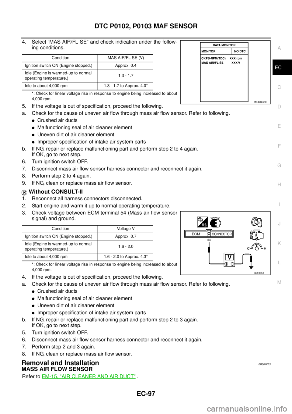
4. Select “MAS AIR/FL SE” and check indication under the follow-
ing conditions.
*: Check for linear voltage rise in response to engine being increased to about
4,000 rpm.
5. If the voltage is out of specification, proceed the following.
a. Check for the cause of uneven air flow through mass air flow sensor. Refer to following.
lCrushed air ducts
lMalfunctioning seal of air cleaner element
lUneven dirt of air cleaner element
lImproper specification of intake air system parts
b. If NG, repair or replace malfunctioning part and perform step 2 to 4 again.
IfOK,gotonextstep.
6. Turn ignition switch OFF.
7. Disconnect mass air flow sensor harness connector and reconnect it again.
8. Performstep2to4again.
9. If NG, clean or replace mass air flow sensor.
Without CONSULT-II
1. Reconnect all harness connectors disconnected.
2. Start engine and warm it up to normal operating temperature.
3. Check voltage between ECM terminal 54 (Mass air flow sensor
signal) and ground.
*: Check for linear voltage rise in response to engine being increased to about
4,000 rpm.
4. If the voltage is out of specification, proceed the following.
a. Check for the cause of uneven air flow through mass air flow sensor. Refer to following.
lCrushed air ducts
lMalfunctioning seal of air cleaner element
lUneven dirt of air cleaner element
lImproper specification of intake air system parts
b. If NG, repair or replace malfunctioning part and perform step 2 to 3 again.
IfOK,gotonextstep.
5. Turn ignition switch OFF.
6. Disconnect mass air flow sensor harness connector and reconnect it again.
7. Perform step 2 and 3 again.
8. If NG, clean or replace mass air flow sensor.
Removal and InstallationEBS01KE3
MASS AIR FLOW SENSOR
Refer toEM-15, "AIR CLEANER AND AIR DUCT".
Condition MAS AIR/FL SE (V)
Ignition switch ON (Engine stopped.) Approx. 0.4
Idle (Engine is warmed-up to normal
operating temperature.)1.3 - 1.7
Idle to about 4,000 rpm 1.3 - 1.7 to Approx. 4.0*
MBIB1240E
Condition Voltage V
Ignition switch ON (Engine stopped.) Approx. 0.7
Idle (Engine is warmed-up to normal
operating temperature.)1.6 - 2.0
Idle to about 4,000 rpm 1.6 - 2.0 to Approx. 4.3*
SEF865T
Page 1083 of 3171
DTC P0117, P0118 ECT SENSOR
EC-103
C
D
E
F
G
H
I
J
K
L
MA
EC
DTC P0117, P0118 ECT SENSORPFP:22630
DescriptionEBS01KEB
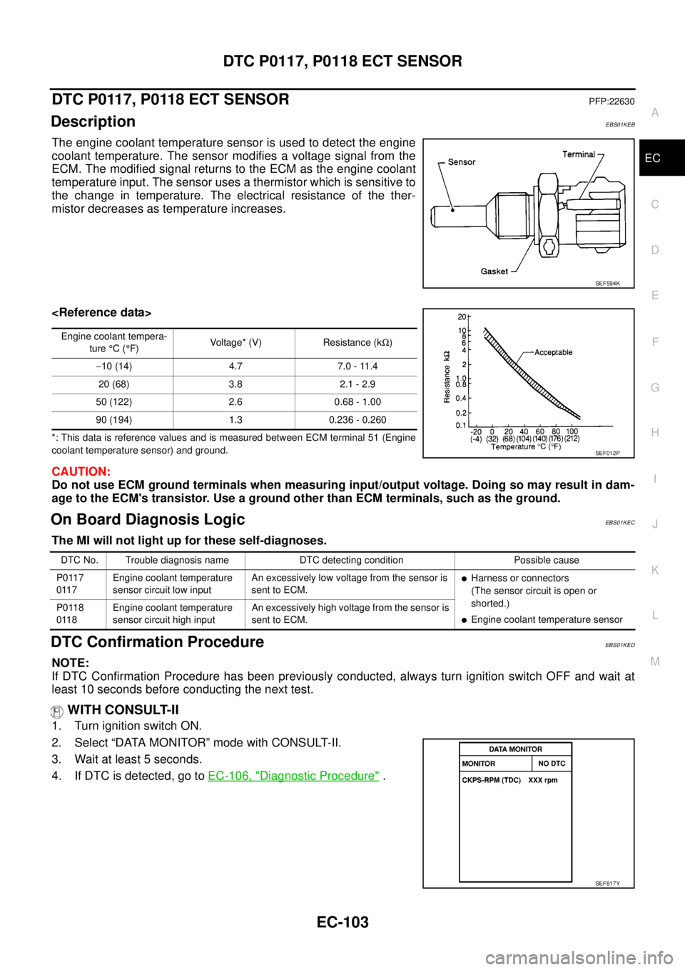
The engine coolant temperature sensor is used to detect the engine
coolant temperature. The sensor modifies a voltage signal from the
ECM. The modified signal returns to the ECM as the engine coolant
temperature input. The sensor uses a thermistor which is sensitive to
the change in temperature. The electrical resistance of the ther-
mistor decreases as temperature increases.
*: This data is reference values and is measured between ECM terminal 51 (Engine
coolant temperature sensor) and ground.
CAUTION:
Do not use ECM ground terminals when measuring input/output voltage. Doing so may result in dam-
age to the ECM's transistor. Use a ground other than ECM terminals, such as the ground.
On Board Diagnosis LogicEBS01KEC
The MI will not light up for these self-diagnoses.
DTC Confirmation ProcedureEBS01KED
NOTE:
If DTC Confirmation Procedure has been previously conducted, always turn ignition switch OFF and wait at
least 10 seconds before conducting the next test.
WITH CONSULT-II
1. Turn ignition switch ON.
2. Select “DATA MONITOR” mode with CONSULT-II.
3. Wait at least 5 seconds.
4. If DTC is detected, go toEC-106, "
Diagnostic Procedure".
SEF594K
Engine coolant tempera-
ture°C(°F)Voltage* (V) Resistance (kW)
-10 (14) 4.7 7.0 - 11.4
20 (68) 3.8 2.1 - 2.9
50 (122) 2.6 0.68 - 1.00
90 (194) 1.3 0.236 - 0.260
SEF012P
DTC No. Trouble diagnosis name DTC detecting condition Possible cause
P0117
0117Engine coolant temperature
sensor circuit low inputAn excessively low voltage from the sensor is
sent to ECM.
lHarness or connectors
(The sensor circuit is open or
shorted.)
lEngine coolant temperature sensor P0118
0118Engine coolant temperature
sensor circuit high inputAn excessively high voltage from the sensor is
sent to ECM.
SEF817Y
Page 1086 of 3171
EC-106
DTC P0117, P0118 ECT SENSOR
Diagnostic Procedure
EBS01KEF
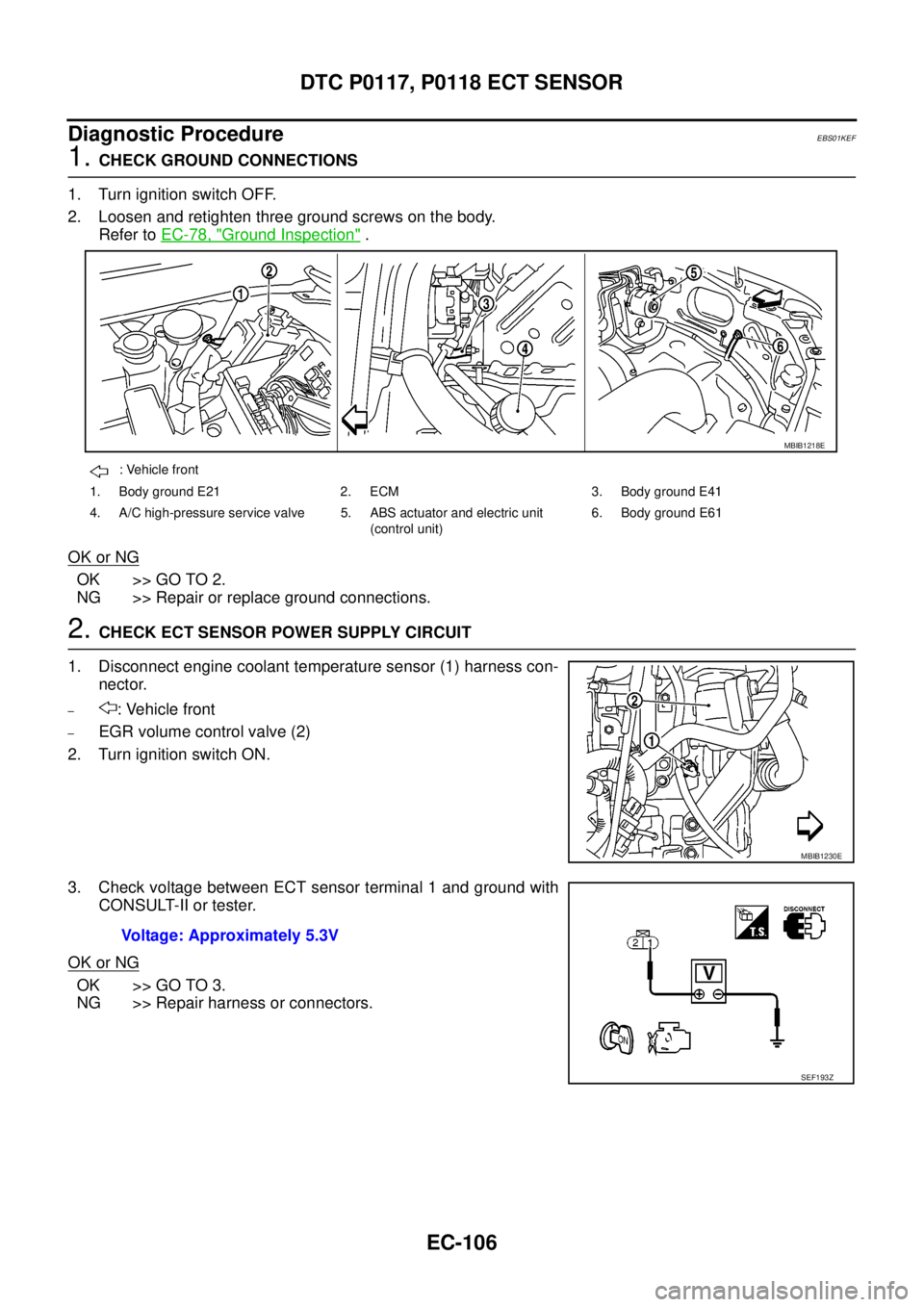
1.CHECK GROUND CONNECTIONS
1. Turn ignition switch OFF.
2. Loosen and retighten three ground screws on the body.
Refer toEC-78, "
Ground Inspection".
OK or NG
OK >> GO TO 2.
NG >> Repair or replace ground connections.
2.CHECK ECT SENSOR POWER SUPPLY CIRCUIT
1. Disconnect engine coolant temperature sensor (1) harness con-
nector.
–: Vehicle front
–EGR volume control valve (2)
2. Turn ignition switch ON.
3. Check voltage between ECT sensor terminal 1 and ground with
CONSULT-II or tester.
OK or NG
OK >> GO TO 3.
NG >> Repair harness or connectors.
: Vehicle front
1. Body ground E21 2. ECM 3. Body ground E41
4. A/C high-pressure service valve 5. ABS actuator and electric unit
(control unit)6. Body ground E61
MBIB1218E
MBIB1230E
Voltage: Approximately 5.3V
SEF193Z
Page 1087 of 3171
DTC P0117, P0118 ECT SENSOR
EC-107
C
D
E
F
G
H
I
J
K
L
MA
EC
3.CHECK ECT SENSOR GROUND CIRCUIT FOR OPEN AND SHORT
1. Turn ignition switch OFF.
2. Disconnect ECM harness connector.
3. Check harness continuity between ECT sensor terminal 2 and ECM terminal 70. Refer to Wiring Diagram.
4. Also check harness for short to ground and short to power.
OK or NG
OK >> GO TO 4.
NG >> Repair open circuit or short to ground or short to power in harness or connectors.
4.CHECK ENGINE COOLANT TEMPERATURE SENSOR
Refer toEC-107, "
Component Inspection".
OK or NG
OK >> GO TO 5.
NG >> Replace engine coolant temperature sensor.
5.CHECK INTERMITTENT INCIDENT
Refer toEC-70, "
TROUBLE DIAGNOSIS FOR INTERMITTENT INCIDENT".
>>INSPECTION END
Component InspectionEBS01KEG
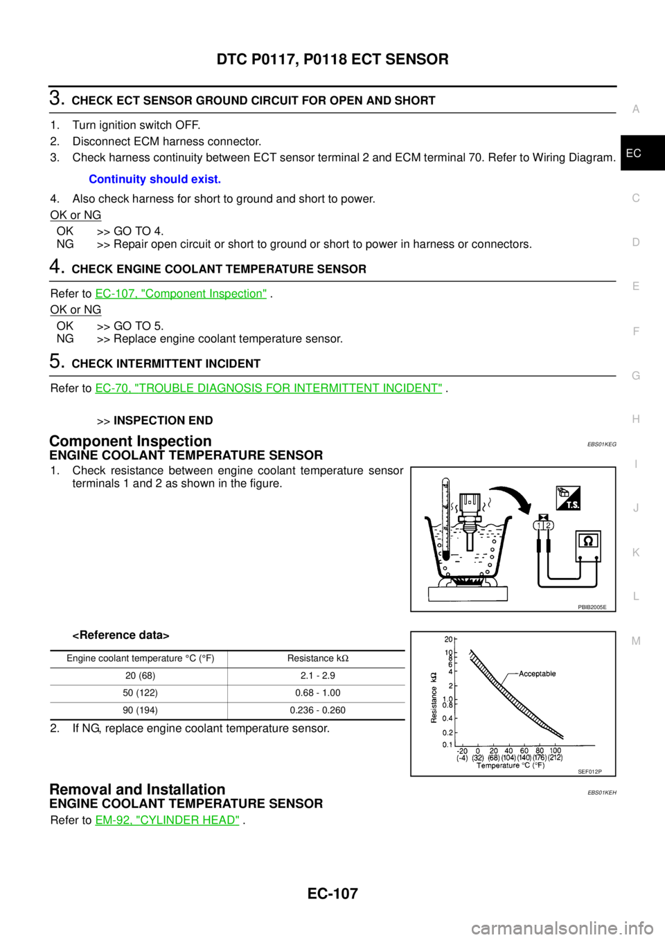
ENGINE COOLANT TEMPERATURE SENSOR
1. Check resistance between engine coolant temperature sensor
terminals 1 and 2 as shown in the figure.
2. If NG, replace engine coolant temperature sensor.
Removal and InstallationEBS01KEH
ENGINE COOLANT TEMPERATURE SENSOR
Refer toEM-92, "CYLINDER HEAD". Continuity should exist.
PBIB2005E
Engine coolant temperature°C(°F) Resistance kW
20 (68) 2.1 - 2.9
50 (122) 0.68 - 1.00
90 (194) 0.236 - 0.260
SEF012P