Page 1119 of 3171
DTC P0217 ENGINE OVER TEMPERATURE
EC-139
C
D
E
F
G
H
I
J
K
L
MA
EC
PROCEDURE A
1.CHECK COOLILNG FAN POWER SUPPLY CIRCUIT
1. Turn ignition switch OFF.
2. Disconnect IPDM E/R harness connectors E14.
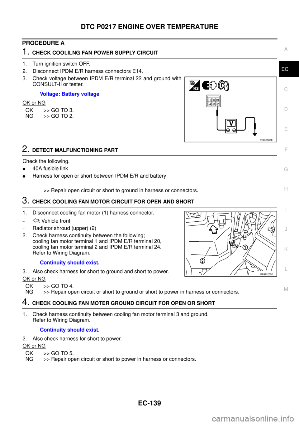
3. Check voltage between IPDM E/R terminal 22 and ground with
CONSULT-II or tester.
OK or NG
OK >> GO TO 3.
NG >> GO TO 2.
2.DETECT MALFUNCTIONING PART
Check the following.
l40A fusible link
lHarness for open or short between IPDM E/R and battery
>> Repair open circuit or short to ground in harness or connectors.
3.CHECK COOLING FAN MOTOR CIRCUIT FOR OPEN AND SHORT
1. Disconnect cooling fan motor (1) harness connector.
–: Vehicle front
–Radiator shroud (upper) (2)
2. Check harness continuity between the following;
cooling fan motor terminal 1 and IPDM E/R terminal 20,
cooling fan motor terminal 2 and IPDM E/R terminal 24.
Refer to Wiring Diagram.
3. Also check harness for short to ground and short to power.
OK or NG
OK >> GO TO 4.
NG >> Repair open circuit or short to ground or short to power in harness or connectors.
4.CHECK COOLING FAN MOTER GROUND CIRCUIT FOR OPEN OR SHORT
1. Check harness continuity between cooling fan motor terminal 3 and ground.
Refer to Wiring Diagram.
2. Also check harness for short to power.
OK or NG
OK >> GO TO 5.
NG >> Repair open circuit or short to power in harness or connectors.Voltage: Battery voltage
PBIB2607E
Continuity should exist.
MBIB1205E
Continuity should exist.
Page 1120 of 3171
EC-140
DTC P0217 ENGINE OVER TEMPERATURE
5.CHECK COOLING FAN MOTOR
Refer toEC-141, "
Component Inspection".
OK or NG
OK >> GO TO 6.
NG >> Replace cooling fan motors.
6.CHECK INTERMITTENT INCIDENT
PerformEC-70, "
TROUBLE DIAGNOSIS FOR INTERMITTENT INCIDENT".
OK or NG
OK >> Replace IPDM E/R. Refer toPG-14, "IPDM E/R (INTELLIGENT POWER DISTRIBUTION MOD-
ULE ENGINE ROOM)".
NG >> Repair or replace harness or connector.
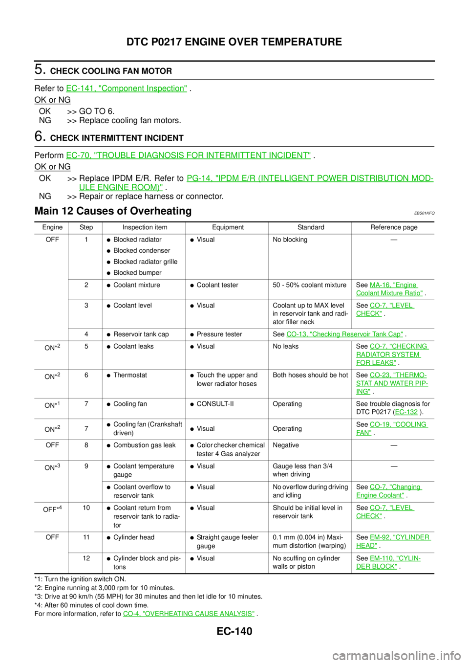
Main 12 Causes of OverheatingEBS01KFQ
*1: Turn the ignition switch ON.
*2: Engine running at 3,000 rpm for 10 minutes.
*3: Drive at 90 km/h (55 MPH) for 30 minutes and then let idle for 10 minutes.
*4: After 60 minutes of cool down time.
For more information, refer toCO-4, "
OVERHEATING CAUSE ANALYSIS". Engine Step Inspection item Equipment Standard Reference page
OFF 1
lBlocked radiator
lBlocked condenser
lBlocked radiator grille
lBlocked bumper
lVisual No blocking —
2
lCoolant mixturelCoolant tester 50 - 50% coolant mixture SeeMA-16, "Engine
Coolant Mixture Ratio".
3
lCoolant levellVisual Coolant up to MAX level
in reservoir tank and radi-
ator filler neckSeeCO-7, "LEVEL
CHECK".
4
lReservoir tank caplPressure tester SeeCO-13, "Checking Reservoir Tank Cap".
ON*
25lCoolant leakslVisual No leaks SeeCO-7, "CHECKING
RADIATOR SYSTEM
FOR LEAKS".
ON*
26lThermostatlTouch the upper and
lower radiator hosesBoth hoses should be hot SeeCO-23, "THERMO-
STAT AND WATER PIP-
ING".
ON*
17lCooling fanlCONSULT-II Operating See trouble diagnosis for
DTC P0217 (EC-132
).
ON*
27lCooling fan (Crankshaft
driven)lVisual OperatingSeeCO-19, "COOLING
FA N".
OFF 8
lCombustion gas leaklColor checker chemical
tester 4 Gas analyzerNegative —
ON*
39lCoolant temperature
gaugelVisual Gauge less than 3/4
when driving—
lCoolant overflow to
reservoir tanklVisual No overflow during driving
and idlingSeeCO-7, "Changing
Engine Coolant".
OFF*
410lCoolant return from
reservoir tank to radia-
torlVisual Should be initial level in
reservoir tankSeeCO-7, "LEVEL
CHECK".
OFF 11
lCylinder headlStraight gauge feeler
gauge0.1 mm (0.004 in) Maxi-
mum distortion (warping)SeeEM-92, "CYLINDER
HEAD".
12
lCylinder block and pis-
tonslVisual No scuffing on cylinder
walls or pistonSeeEM-110, "CYLIN-
DER BLOCK".
Page 1121 of 3171
DTC P0217 ENGINE OVER TEMPERATURE
EC-141
C
D
E
F
G
H
I
J
K
L
MA
EC
Component InspectionEBS01KFR
COOLING FAN MOTOR
1. Disconnect cooling fan motor harness connectors.
2. Supply cooling fan motor terminals with battery voltage and
check operation.
Cooling fan motor should operate.
If NG, replace cooling fan motor.
Cooling fan speedCooling fan motor terminals
(+) (-)
Low (LOW) 1 3
High (HI) 2 3
MBIB1241E
Page 1122 of 3171
EC-142
DTC P0222, P0223 APP SENSOR
DTC P0222, P0223 APP SENSOR
PFP:18002
DescriptionEBS01KFS
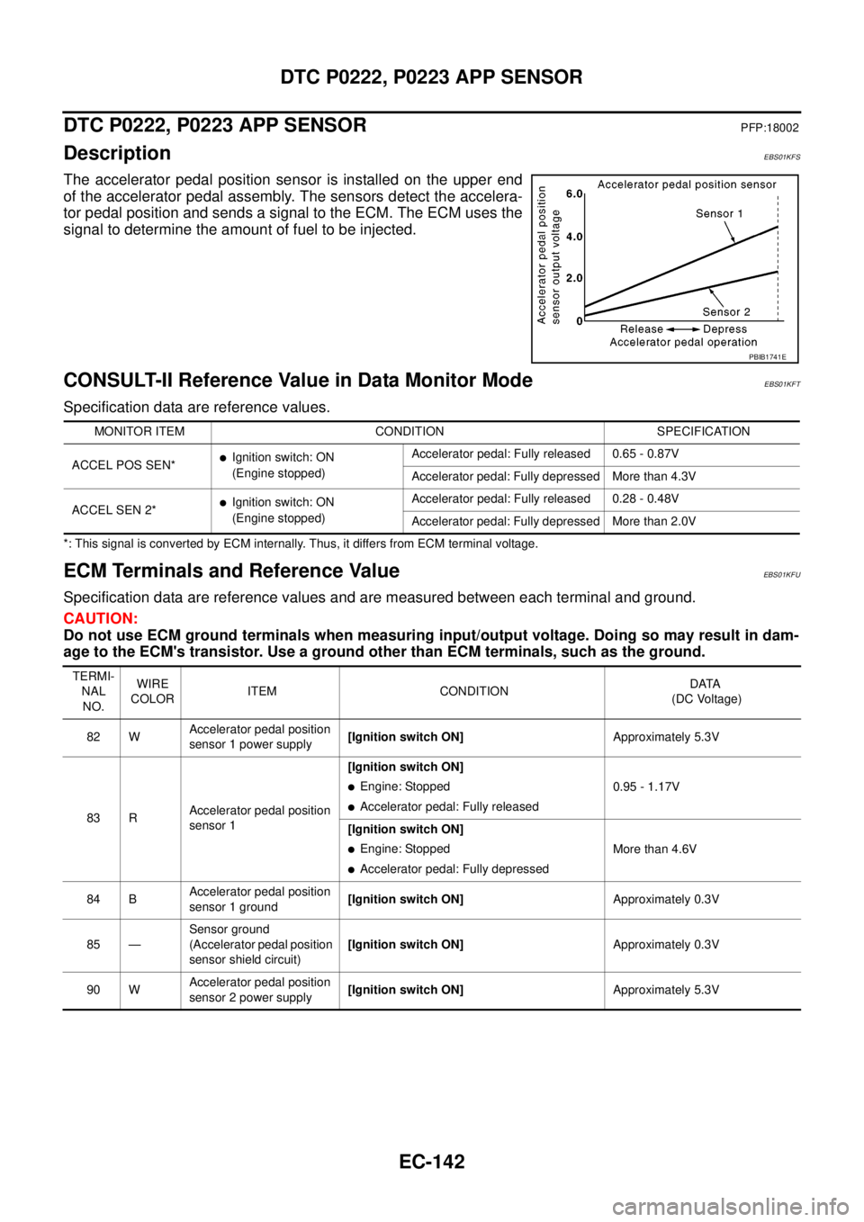
The accelerator pedal position sensor is installed on the upper end
of the accelerator pedal assembly. The sensors detect the accelera-
tor pedal position and sends a signal to the ECM. The ECM uses the
signal to determine the amount of fuel to be injected.
CONSULT-II Reference Value in Data Monitor ModeEBS01KFT
Specification data are reference values.
*: This signal is converted by ECM internally. Thus, it differs from ECM terminal voltage.
ECM Terminals and Reference ValueEBS01KFU
Specification data are reference values and are measured between each terminal and ground.
CAUTION:
Do not use ECM ground terminals when measuring input/output voltage. Doing so may result in dam-
age to the ECM's transistor. Use a ground other than ECM terminals, such as the ground.
PBIB1741E
MONITOR ITEM CONDITION SPECIFICATION
ACCEL POS SEN*
lIgnition switch: ON
(Engine stopped)Accelerator pedal: Fully released 0.65 - 0.87V
Accelerator pedal: Fully depressed More than 4.3V
ACCEL SEN 2*
lIgnition switch: ON
(Engine stopped)Accelerator pedal: Fully released 0.28 - 0.48V
Accelerator pedal: Fully depressed More than 2.0V
TERMI-
NAL
NO.WIRE
COLORITEM CONDITIONDATA
(DC Voltage)
82 WAccelerator pedal position
sensor 1 power supply[Ignition switch ON]Approximately 5.3V
83 RAccelerator pedal position
sensor 1[Ignition switch ON]
lEngine: Stopped
lAccelerator pedal: Fully released0.95 - 1.17V
[Ignition switch ON]
lEngine: Stopped
lAccelerator pedal: Fully depressedMore than 4.6V
84 BAccelerator pedal position
sensor 1 ground[Ignition switch ON]Approximately 0.3V
85 —Sensor ground
(Accelerator pedal position
sensor shield circuit)[Ignition switch ON]Approximately 0.3V
90 WAccelerator pedal position
sensor 2 power supply[Ignition switch ON]Approximately 5.3V
Page 1123 of 3171
DTC P0222, P0223 APP SENSOR
EC-143
C
D
E
F
G
H
I
J
K
L
MA
EC
On Board Diagnosis LogicEBS01KFV
The MI will not light up for these self-diagnoses.
NOTE:
If DTC P0222 or P0223 is displayed with DTC P0652 or P0653, first perform the trouble diagnosis for
DTC P0652 or P0653. Refer toEC-227, "
DTC P0652, P0653 SENSOR POWER SUPPLY".
DTC Confirmation ProcedureEBS01KFW
NOTE:
If DTC Confirmation Procedure has been previously conducted, always turn ignition switch OFF and wait at
least 10 seconds before conducting the next test.
WITH CONSULT-II
1. Turn ignition switch ON.
2. Select “DATA MONITOR” mode with CONSULT-II.
3. Wait at least 5 seconds.
4. If DTC is detected, go toEC-145, "
Diagnostic Procedure".
WITHOUT CONSULT-II
1. Turn ignition switch ON and wait at least 5 seconds.
2. Turn ignition switch OFF, wait at least 10 seconds and then turn ON.
3. Perform Diagnostic Test Mode II (Self-diagnostic results) with ECM.
4. If DTC is detected, go toEC-145, "
Diagnostic Procedure".
91 RAccelerator pedal position
sensor 2[Ignition switch ON]
lEngine: Stopped
lAccelerator pedal: Fully released0.58 - 0.78V
[Ignition switch ON]
lEngine: Stopped
lAccelerator pedal: Fully depressedMore than 2.3V
92 BAccelerator pedal position
sensor 2 ground[Ignition switch ON]Approximately 0.3V TERMI-
NAL
NO.WIRE
COLORITEM CONDITIONDATA
(DC Voltage)
DTC No. Trouble diagnosis name DTC detecting condition Possible cause
P0222
0222Accelerator pedal position
sensor 2 circuit low inputAn excessively low voltage from the APP sensor
2 is sent to ECM.
lHarness or connectors
(The APP sensor 2 circuit is open or
shorted.)
lAccelerator pedal position sensor
(Accelerator pedal position sensor 2) P0223
0223Accelerator pedal position
sensor 2 circuit high inputAn excessively high voltage from the APP sen-
sor 2 is sent to ECM.
SEF817Y
Page 1127 of 3171
DTC P0234 TC SYSTEM
EC-147
C
D
E
F
G
H
I
J
K
L
MA
EC
DTCP0234TCSYSTEMPFP:14411
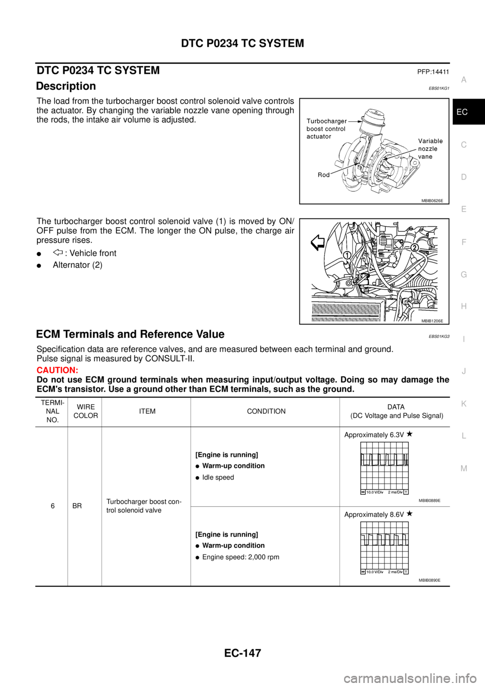
DescriptionEBS01KG1
The load from the turbocharger boost control solenoid valve controls
the actuator. By changing the variable nozzle vane opening through
the rods, the intake air volume is adjusted.
The turbocharger boost control solenoid valve (1) is moved by ON/
OFF pulse from the ECM. The longer the ON pulse, the charge air
pressure rises.
l: Vehicle front
lAlternator (2)
ECM Terminals and Reference ValueEBS01KG3
Specification data are reference valves, and are measured between each terminal and ground.
Pulse signal is measured by CONSULT-II.
CAUTION:
Do not use ECM ground terminals when measuring input/output voltage. Doing so may damage the
ECM's transistor. Use a ground other than ECM terminals, such as the ground.
MBIB0626E
MBIB1206E
TERMI-
NAL
NO.WIRE
COLORITEM CONDITIONDATA
(DC Voltage and Pulse Signal)
6BRTurbocharger boost con-
trol solenoid valve[Engine is running]
lWarm-up condition
lIdle speedApproximately 6.3V
[Engine is running]
lWarm-up condition
lEngine speed: 2,000 rpmApproximately 8.6V
MBIB0889E
MBIB0890E
Page 1128 of 3171
EC-148
DTC P0234 TC SYSTEM
: Average voltage for pulse signal (Actual pulse signal can be confirmed by oscilloscope.)
On Board Diagnosis LogicEBS01KG4
The MI will not light up for this self-diagnosis.
NOTE:
If DTC P0234 is displayed with DTC P0652 or P0653, first perform the trouble diagnosis for DTC P0652
or P0653. Refer toEC-227, "
DTC P0652, P0653 SENSOR POWER SUPPLY".
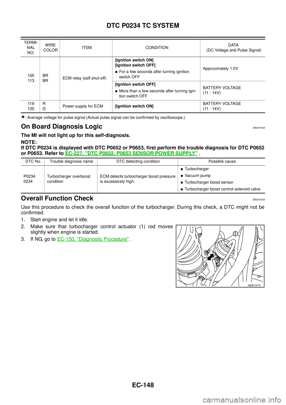
Overall Function CheckEBS01KG5
Use this procedure to check the overall function of the turbocharger. During this check, a DTC might not be
confirmed.
1. Start engine and let it idle.
2. Make sure that turbocharger control actuator (1) rod moves
slightly when engine is started.
3. If NG, go toEC-150, "
Diagnostic Procedure".
105
11 3BR
BRECM relay (self shut-off)[Ignition switch ON]
[Ignition switch OFF]lFor a few seconds after turning ignition
switch OFFApproximately 1.0V
[Ignition switch OFF]
lMore than a few seconds after turning igni-
tion switch OFFBATTERY VOLTAGE
(11 - 14V)
11 9
120R
GPower supply for ECM[Ignition switch ON]BATTERY VOLTAGE
(11 - 14V) TERMI-
NAL
NO.WIRE
COLORITEM CONDITIONDATA
(DC Voltage and Pulse Signal)
DTC No. Trouble diagnosis name DTC detecting condition Possible cause
P0234
0234Turbocharger overboost
conditionECM detects turbocharger boost pressure
is excessively high.
lTurbocharger
lVa c u u m p u m p
lTurbocharger boost sensor
lTurbocharger boost control solenoid valve
MBIB1207E
Page 1130 of 3171
EC-150
DTC P0234 TC SYSTEM
Diagnostic Procedure
EBS01KG7
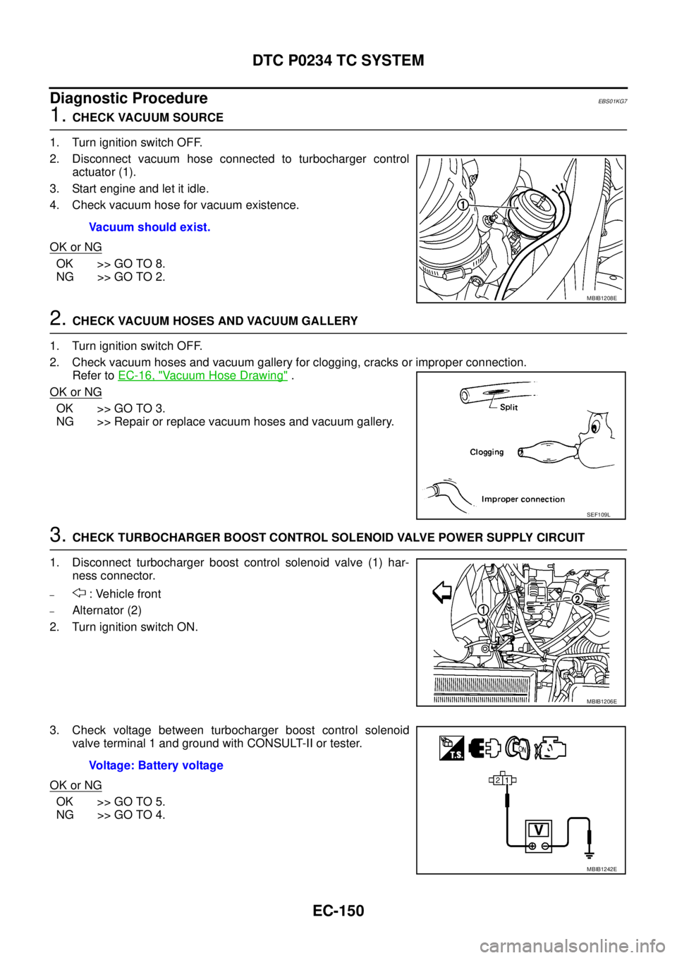
1.CHECK VACUUM SOURCE
1. Turn ignition switch OFF.
2. Disconnect vacuum hose connected to turbocharger control
actuator (1).
3. Start engine and let it idle.
4. Check vacuum hose for vacuum existence.
OK or NG
OK >> GO TO 8.
NG >> GO TO 2.
2.CHECK VACUUM HOSES AND VACUUM GALLERY
1. Turn ignition switch OFF.
2. Check vacuum hoses and vacuum gallery for clogging, cracks or improper connection.
Refer toEC-16, "
Vacuum Hose Drawing".
OK or NG
OK >> GO TO 3.
NG >> Repair or replace vacuum hoses and vacuum gallery.
3.CHECK TURBOCHARGER BOOST CONTROL SOLENOID VALVE POWER SUPPLY CIRCUIT
1. Disconnect turbocharger boost control solenoid valve (1) har-
ness connector.
–: Vehicle front
–Alternator (2)
2. Turn ignition switch ON.
3. Check voltage between turbocharger boost control solenoid
valve terminal 1 and ground with CONSULT-II or tester.
OK or NG
OK >> GO TO 5.
NG >> GO TO 4.Vacuum should exist.
MBIB1208E
SEF109L
MBIB1206E
Voltage: Battery voltage
MBIB1242E