Page 1170 of 3171
EC-190
DTC P0504 ASCD BRAKE SWITCH
On Board Diagnosis Logic
EBS01KHW
The MI will not light up for this diagnosis.
DTC confirmation ProcedureEBS01KHX
CAUTION:
Always drive vehicle at a safe speed.
NOTE:
If DTC Confirmation Procedure has been previously conducted, always turn ignition switch OFF and wait at
least 10 seconds before conducting the next test.
TESTING CONDITION:
Steps 3 and 4 may be conducted with the drive wheels lifted in the shop or by driving the vehicle. If a
road test is expected to be easier, it is unnecessary to lift the vehicle.
WITH CONSULT-II
1. Start engine.
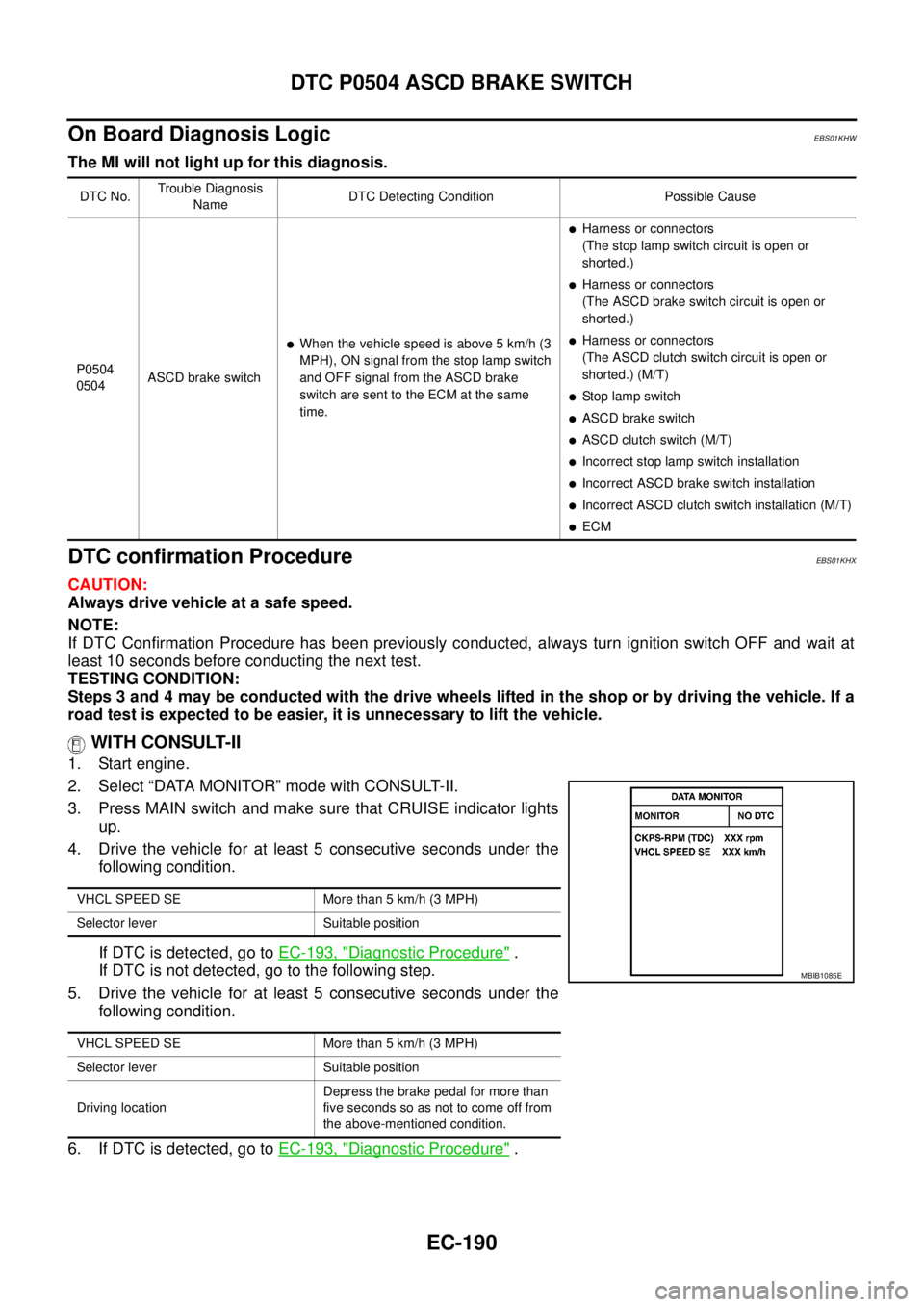
2. Select “DATA MONITOR” mode with CONSULT-II.
3. Press MAIN switch and make sure that CRUISE indicator lights
up.
4. Drive the vehicle for at least 5 consecutive seconds under the
following condition.
If DTC is detected, go toEC-193, "
Diagnostic Procedure".
If DTC is not detected, go to the following step.
5. Drive the vehicle for at least 5 consecutive seconds under the
following condition.
6. If DTC is detected, go toEC-193, "
Diagnostic Procedure".
DTC No.Trouble Diagnosis
NameDTC Detecting Condition Possible Cause
P0504
0504ASCD brake switch
lWhen the vehicle speed is above 5 km/h (3
MPH), ON signal from the stop lamp switch
and OFF signal from the ASCD brake
switch are sent to the ECM at the same
time.
lHarness or connectors
(The stop lamp switch circuit is open or
shorted.)
lHarness or connectors
(The ASCD brake switch circuit is open or
shorted.)
lHarness or connectors
(The ASCD clutch switch circuit is open or
shorted.) (M/T)
lStop lamp switch
lASCD brake switch
lASCD clutch switch (M/T)
lIncorrectstoplampswitchinstallation
lIncorrect ASCD brake switch installation
lIncorrect ASCD clutch switch installation (M/T)
lECM
VHCL SPEED SE More than 5 km/h (3 MPH)
Selector lever Suitable position
VHCL SPEED SE More than 5 km/h (3 MPH)
Selector lever Suitable position
Driving locationDepress the brake pedal for more than
five seconds so as not to come off from
the above-mentioned condition.
MBIB1085E
Page 1171 of 3171
DTC P0504 ASCD BRAKE SWITCH
EC-191
C
D
E
F
G
H
I
J
K
L
MA
EC
WITHOUT CONSULT-II
1. Start engine.
2. Press MAIN switch and make sure that CRUISE indicator lights up.
3. Drive the vehicle for at least 5 consecutive seconds under the following condition.
4. Turn ignition switch OFF, wait at least 10 seconds and then turn ON.
5. Perform Diagnostic Test Mode II (Self-diagnostic results) with ECM.
If DTC is detected, go toEC-193, "
Diagnostic Procedure".
If DTC is not detected, go to the following step.
6. Start engine.
7. Drive the vehicle for at least 5 consecutive seconds under the following condition.
8. If DTC is detected, go toEC-193, "
Diagnostic Procedure".
Vehiclespeed Morethan5km/h(3MPH)
Selector lever Suitable position
Vehiclespeed Morethan5km/h(3MPH)
Selector lever Suitable position
Driving locationDepress the brake pedal for more than
five seconds so as not to come off from
the above-mentioned condition.
Page 1183 of 3171
DTC P0563 BATTERY VOLTAGE
EC-203
C
D
E
F
G
H
I
J
K
L
MA
EC
DTC P0563 BATTERY VOLTAGEPFP:24410
On Board Diagnosis LogicEBS01KI1
The MI will not light up for this self-diagnosis.
DTC Confirmation ProcedureEBS01KI2
NOTE:
If DTC Confirmation Procedure has been previously conducted, always turn ignition switch OFF and wait at
least 10 seconds before conducting the next test.
WITH CONSULT-II
1. Turn ignition switch ON.
2. Select “DATA MONITOR” mode with CONSULT-II.
3. Start engine and let it idle for at least 35 seconds.
4. If DTC is detected, go toEC-203, "
Diagnostic Procedure".
WITHOUT CONSULT-II
1. Start engine and let it idle for at least 35 seconds.
2. Turn ignition switch OFF, wait at least 10 seconds and then turn ON.
3. Perform Diagnostic Test Mode II (Self-diagnostic results) with ECM.
4. If DTC is detected, go toEC-203, "
Diagnostic Procedure".
Diagnostic ProcedureEBS01KI3
1.INSPECTION START
Are jumper cables connected for the jump starting?
Ye s o r N o
Ye s > > G O T O 3 .
No >> GO TO 2.
2.CHECK BATTERY AND ALTERNATOR
Check that the proper type of battery and type of alternator are installed.
Refer to,SC-5, "
BATTERY"andSC-14, "CHARGING SYSTEM".
OK or NG
OK >> GO TO 5.
NG >> Replace with the proper one.
DTC No. Trouble diagnosis name DTC detecting condition Possible cause
P0563
0563Battery voltage highAn excessively high voltage from the battery is
sent to ECM.
lBattery
lBattery terminal
lAlternator
lIncorrect jump starting
SEF817Y
Page 1193 of 3171
DTC P0605 ECM
EC-213
C
D
E
F
G
H
I
J
K
L
MA
EC
DTC P0605 ECMPFP:23710
DescriptionEBS01KIC
The ECM consists of a microcomputer and connectors for signal
input and output and for power supply. The ECM controls the engine.
On Board Diagnosis LogicEBS01KID
DTC Confirmation ProcedureEBS01KIE
NOTE:
If DTC Confirmation Procedure has been previously conducted, always turn ignition switch OFF and wait at
least 10 seconds before conducting the next test.
WITH CONSULT-II
1. Turn ignition switch ON.
2. Select “DATA MONITOR” mode with CONSULT-II.
3. Wait at least 5 seconds.
4. If DTC is detected, go toEC-214, "
Diagnostic Procedure".
WITHOUT CONSULT-II
1. Turn ignition switch ON and wait at least 5 seconds.
2. Turn ignition switch OFF, wait at least 10 seconds and then turn ON.
3. Perform Diagnostic Test Mode II (Self-diagnostic results) with ECM.
4. If DTC is detected, go toEC-214, "
Diagnostic Procedure".
MBIB0625E
DTC No. Trouble diagnosis name DTC detecting condition Possible cause
P0605
0605Engine control module
(ROM)ECM ROM is malfunctioning.
lECM
SEF817Y
Page 1195 of 3171
DTC P0606 ECM
EC-215
C
D
E
F
G
H
I
J
K
L
MA
EC
DTC P0606 ECMPFP:23710
DescriptionEBS01KIG
The ECM consists of a microcomputer and connectors for signal
input and output and for power supply. The ECM controls the engine.
On Board Diagnosis LogicEBS01KIH
DTC Confirmation ProcedureEBS01KII
NOTE:
If DTC Confirmation Procedure has been previously conducted, always turn ignition switch OFF and wait at
least 10 seconds before conducting the next test.
WITH CONSULT-II
1. Turn ignition switch ON.
2. Select “DATA MONITOR” mode with CONSULT-II.
3. Wait at least 5 seconds.
4. If DTC is detected, go toEC-216, "
Diagnostic Procedure".
WITHOUT CONSULT-II
1. Turn ignition switch ON and wait at least 5 seconds.
2. Turn ignition switch OFF, wait at least 10 seconds and then turn ON.
3. Perform Diagnostic Test Mode II (Self-diagnostic results) with ECM.
4. If DTC is detected, go toEC-216, "
Diagnostic Procedure".
MBIB0625E
DTC No. Trouble diagnosis name DTC detecting condition Possible cause
P0606
0606Engine control module
(Processor)ECM calculation function is malfunctioning.
lECM
SEF817Y
Page 1197 of 3171
DTC P0628, P0629 FUEL PUMP
EC-217
C
D
E
F
G
H
I
J
K
L
MA
EC
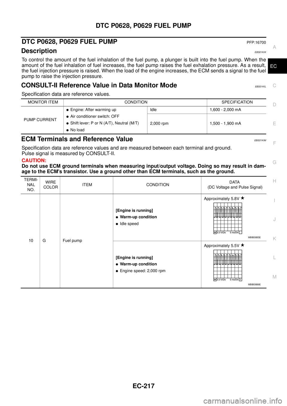
DTC P0628, P0629 FUEL PUMPPFP:16700
DescriptionEBS01KIK
To control the amount of the fuel inhalation of the fuel pump, a plunger is built into the fuel pump. When the
amount of the fuel inhalation of fuel increases, the fuel pump raises the fuel exhalation pressure. As a result,
the fuel injection pressure is raised. When the load of the engine increases, the ECM sends a signal to the fuel
pump to raise the injection pressure.
CONSULT-II Reference Value in Data Monitor ModeEBS01KIL
Specification data are reference values.
ECM Terminals and Reference ValueEBS01KIM
Specification data are reference values and are measured between each terminal and ground.
Pulse signal is measured by CONSULT-II.
CAUTION:
Do not use ECM ground terminals when measuring input/output voltage. Doing so may result in dam-
age to the ECM's transistor. Use a ground other than ECM terminals, such as the ground.
MONITOR ITEM CONDITION SPECIFICATION
PUMP CURRENT
lEngine: After warming up
lAir conditioner switch: OFF
lShift lever: P or N (A/T), Neutral (M/T)
lNo loadIdle 1,600 - 2,000 mA
2,000 rpm 1,500 - 1,900 mA
TERMI-
NAL
NO.WIRE
COLORITEM CONDITIONDATA
(DC Voltage and Pulse Signal)
10 G Fuel pump[Engine is running]
lWarm-up condition
lIdle speedApproximately 5.8V
[Engine is running]
lWarm-up condition
lEngine speed: 2,000 rpmApproximately 5.5V
MBIB0885E
MBIB0886E
Page 1198 of 3171

EC-218
DTC P0628, P0629 FUEL PUMP
: Average voltage for pulse signal (Actual pulse signal can be confirmed by oscilloscope.)
On Board Diagnosis LogicEBS01KIN
DTC Confirmation ProcedureEBS01KIO
NOTE:
If DTC Confirmation Procedure has been previously conducted, always turn ignition switch OFF and wait at
least 10 seconds before conducting the next test.
WITH CONSULT-II
1. Start engine and warm it up to normal operating temperature.
2. Select “DATA MONITOR” mode with CONSULT-II.
3. Let engine idle for at least 5 seconds.
4. If DTC is detected, go toEC-220, "
Diagnostic Procedure".
WITHOUT CONSULT-II
1. Start engine and warm it up to normal operating temperature.
2. Let engine idle for at least 5 seconds.
3. Turn ignition switch OFF, wait at least 10 seconds and then turn ON.
4. Perform Diagnostic Test Mode II (Self-diagnostic results) with ECM.
5. If DTC is detected, go toEC-220, "
Diagnostic Procedure".
29 B Fuel pump[Engine is running]
lWarm-up condition
lIdle speed0.5 - 1.0V
[Engine is running]
lWarm-up condition
lEngine speed: 2,000 rpm0.5 - 1.0V TERMI-
NAL
NO.WIRE
COLORITEM CONDITIONDATA
(DC Voltage and Pulse Signal)
MBIB0887E
MBIB0888E
DTC No. Trouble diagnosis name DTC detecting condition Possible cause
P0628
0628Fuel pump control circuit
low inputECM detects a control circuit for the fuel pump is
open or short to ground.
lHarness or connectors
(The fuel pump circuit is open or
shorted.)
lFuel pump P0629
0629Fuel pump control circuit
high outputECM detects a control circuit for the fuel pump is
short to power.
SEF817Y
Page 1202 of 3171

EC-222
DTC P0642, P0643 SENSOR POWER SUPPLY
DTC P0642, P0643 SENSOR POWER SUPPLY
PFP:18002
ECM Terminals and Reference ValueEBS01KIT
Specification data are reference values and are measured between each terminal and ground.
CAUTION:
Do not use ECM ground terminals when measuring input/output voltage. Doing so may result in dam-
age to the ECM's transistor. Use a ground other than ECM terminals, such as the ground.
On Board Diagnosis LogicEBS01KIU
The MI will not light up for these self-diagnoses.
TERMI-
NAL
NO.WIRE
COLORITEM CONDITIONDATA
(DC Voltage)
82 WAccelerator pedal position sensor 1
power supply[Ignition switch ON]Approximately 5.3V
83 R Accelerator pedal position sensor 1[Ignition switch ON]
lEngine: Stopped
lAccelerator pedal: Fully released0.95 - 1.17V
[Ignition switch ON]
lEngine: Stopped
lAccelerator pedal: Fully
depressedMore than 4.6V
84 BAccelerator pedal position sensor 1
ground[Engine is running]
lWarm-up condition
lIdle speedApproximately 0.3V
85 —Sensor ground
(Accelerator pedal position sensor
shield circuit)[Engine is running]
lWarm-up condition
lIdle speedApproximately 0.3V
90 WAccelerator pedal position sensor 2
power supply[Ignition switch ON]Approximately 5.3V
91 R Accelerator pedal position sensor 2[Ignition switch ON]
lEngine: Stopped
lAccelerator pedal: Fully released0.58 - 0.78V
[Ignition switch ON]
lEngine: Stopped
lAccelerator pedal: Fully
depressedMore than 2.3V
92 BAccelerator pedal position sensor 2
ground[Engine is running]
lWarm-up condition
lIdle speedApproximately 0.3V
DTC No. Trouble diagnosis name DTC detecting condition Possible cause
P0642
0642Sensor power supply cir-
cuit lowECM detects a voltage of power source for sen-
sor is excessively low.
lHarness or connectors
(The APP sensor 1 power supply cir-
cuit is shorted.)
lAccelerator pedal position sensor
(Accelerator pedal position sensor 1) P0643
0643Sensor power supply cir-
cuit highECM detects a voltage of power source for Sen-
sor is excessively high.