Page 1409 of 3171
CATALYST
EM-27
C
D
E
F
G
H
I
J
K
L
MA
EM
INSTALLATION
Note the following, and install in the reverse order of removal.
lIf stud bolts of turbocharger were removed, tighten them to the specified torque.
lIf stud bolts of catalyst were removed, tighten them to the specified torque.
lPushing bracket against the cylinder block and the catalyst, temporarily tighten the mounting bolt. And
then tighten it to the specified torque.: 25.5 N·m (2.6 kg-m, 19 ft-lb)
: 45.0 N·m (4.6 kg-m, 33 ft-lb)
Page 1411 of 3171

TURBO CHARGER
EM-29
C
D
E
F
G
H
I
J
K
L
MA
EM
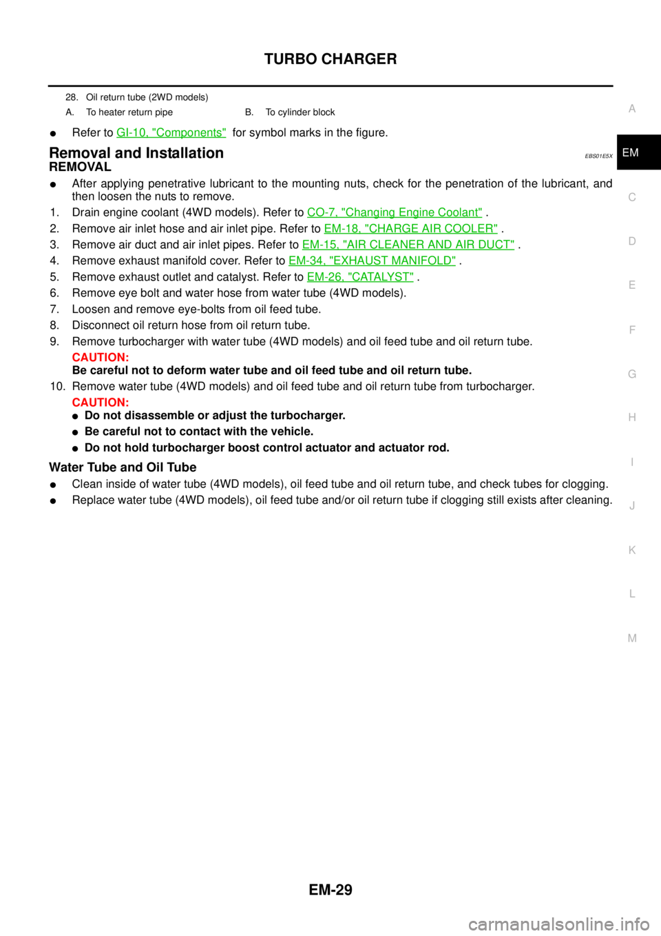
lRefer toGI-10, "Components"for symbol marks in the figure.
Removal and InstallationEBS01E5X
REMOVAL
lAfter applying penetrative lubricant to the mounting nuts, check for the penetration of the lubricant, and
then loosen the nuts to remove.
1. Drain engine coolant (4WD models). Refer toCO-7, "
Changing Engine Coolant".
2. Remove air inlet hose and air inlet pipe. Refer toEM-18, "
CHARGE AIR COOLER".
3. Remove air duct and air inlet pipes. Refer toEM-15, "
AIR CLEANER AND AIR DUCT".
4. Remove exhaust manifold cover. Refer toEM-34, "
EXHAUST MANIFOLD".
5. Remove exhaust outlet and catalyst. Refer toEM-26, "
CATALYST".
6. Remove eye bolt and water hose from water tube (4WD models).
7. Loosen and remove eye-bolts from oil feed tube.
8. Disconnect oil return hose from oil return tube.
9. Remove turbocharger with water tube (4WD models) and oil feed tube and oil return tube.
CAUTION:
Be careful not to deform water tube and oil feed tube and oil return tube.
10. Remove water tube (4WD models) and oil feed tube and oil return tube from turbocharger.
CAUTION:
lDo not disassemble or adjust the turbocharger.
lBe careful not to contact with the vehicle.
lDo not hold turbocharger boost control actuator and actuator rod.
Water Tube and Oil Tube
lClean inside of water tube (4WD models), oil feed tube and oil return tube, and check tubes for clogging.
lReplace water tube (4WD models), oil feed tube and/or oil return tube if clogging still exists after cleaning.
28. Oil return tube (2WD models)
A. To heater return pipe B. To cylinder block
Page 1420 of 3171
![NISSAN NAVARA 2005 Repair Workshop Manual EM-38
OIL PAN AND OIL STRAINER
15. Loosen bolts in the reverse order of illustration to remove oil pan
upper.
16. Remove oil pan upper.
lInsert the seal cutter [SST] between oil pan upper and cylin-
d NISSAN NAVARA 2005 Repair Workshop Manual EM-38
OIL PAN AND OIL STRAINER
15. Loosen bolts in the reverse order of illustration to remove oil pan
upper.
16. Remove oil pan upper.
lInsert the seal cutter [SST] between oil pan upper and cylin-
d](/manual-img/5/57362/w960_57362-1419.png)
EM-38
OIL PAN AND OIL STRAINER
15. Loosen bolts in the reverse order of illustration to remove oil pan
upper.
16. Remove oil pan upper.
lInsert the seal cutter [SST] between oil pan upper and cylin-
der block. Slide the seal cutter by tapping on the side of the
seal cutter with a hammer. Remove oil pan upper.
lBe careful not to damage aluminum mating surface.
lDo not insert screwdriver, or oil pan flange will be
deformed.
INSPECTION AFTER REMOVAL
Clean oil strainer if any object attached.
INSTALLATION
Note the following, and install in the reverse order of removal.
lInstall oil pan upper with the following procedure.
–Use the scraper (A) to remove old liquid gasket from mating sur-
face of oil pan upper (1).
•Also remove old liquid gasket from mating surface of cylin-
der block and rear chain case.
•Remove old liquid gasket from the bolt hole and thread.
–Apply a continuous bead of liquid gasket with the tube presser
[SST: WS39930000] to areas shown in the figure.
Use Genuine Liquid Gasket or equivalent.
CAUTION:
lAt the 2 bolt holes marked , liquid gasket should be
applied outside holes.
lBe sure liquid gasket is 3.5 to 4.5 mm (0.138 to 0.177 in)
or 4.5 to 5.5 mm (0.177 to 0.217 in) wide. (Be careful that
the diameter of the liquid gasket bead is different around
the front.)
lAttaching should be done within 5 minutes after coating.
–Install oil pan upper.
: Vehicle front
PBIC3431E
SEM365EA
PBIC3432E
: Vehicle front
PBIC3433E
Page 1443 of 3171

CAMSHAFT
EM-61
C
D
E
F
G
H
I
J
K
L
MA
EM
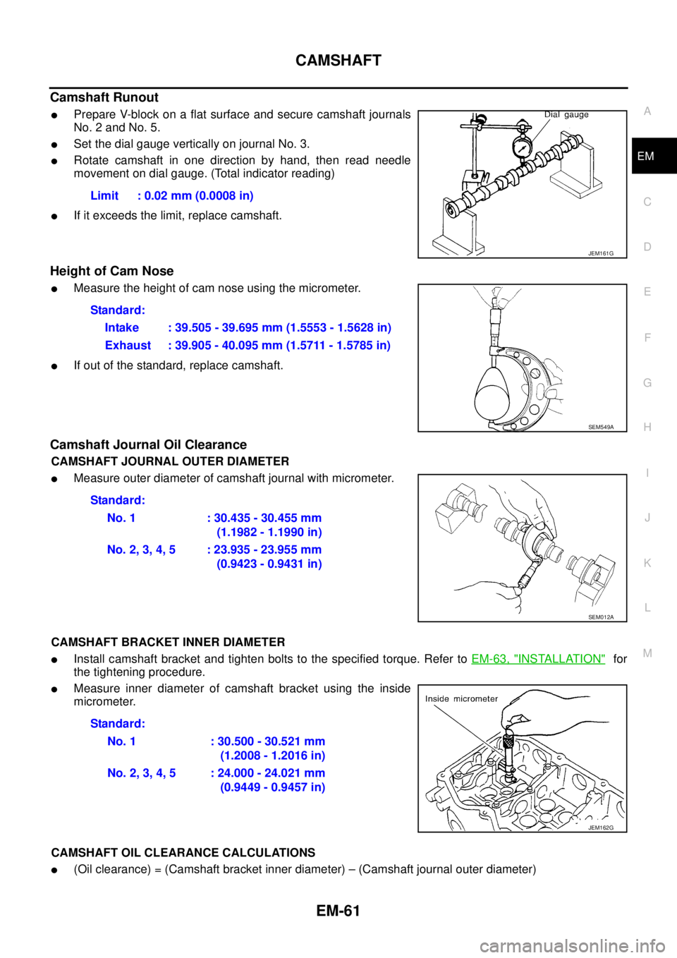
Camshaft Runout
lPrepare V-block on a flat surface and secure camshaft journals
No. 2 and No. 5.
lSet the dial gauge vertically on journal No. 3.
lRotate camshaft in one direction by hand, then read needle
movement on dial gauge. (Total indicator reading)
lIf it exceeds the limit, replace camshaft.
Height of Cam Nose
lMeasure the height of cam nose using the micrometer.
lIf out of the standard, replace camshaft.
Camshaft Journal Oil Clearance
CAMSHAFT JOURNAL OUTER DIAMETER
lMeasure outer diameter of camshaft journal with micrometer.
CAMSHAFT BRACKET INNER DIAMETER
lInstall camshaft bracket and tighten bolts to the specified torque. Refer toEM-63, "INSTALLATION"for
the tightening procedure.
lMeasure inner diameter of camshaft bracket using the inside
micrometer.
CAMSHAFT OIL CLEARANCE CALCULATIONS
l(Oil clearance) = (Camshaft bracket inner diameter) – (Camshaft journal outer diameter)Limit : 0.02 mm (0.0008 in)
JEM161G
Standard:
Intake : 39.505 - 39.695 mm (1.5553 - 1.5628 in)
Exhaust : 39.905 - 40.095 mm (1.5711 - 1.5785 in)
SEM549A
Standard:
No. 1 : 30.435 - 30.455 mm
(1.1982 - 1.1990 in)
No.2,3,4,5 :23.935-23.955mm
(0.9423 - 0.9431 in)
SEM012A
Standard:
No. 1 : 30.500 - 30.521 mm
(1.2008 - 1.2016 in)
No.2,3,4,5 :24.000-24.021mm
(0.9449 - 0.9457 in)
JEM162G
Page 1448 of 3171

EM-66
CAMSHAFT
Valve Clearance
EBS01E67
INSPECTION
lWhen the camshaft or parts in connection with valves are removed or replaced, and a malfunction has
occurred (poor starting, idling, or other malfunction) due to the misadjustment of the valve clearance,
inspect as follows.
lInspect and adjust when the engine is cool (at normal temperature).
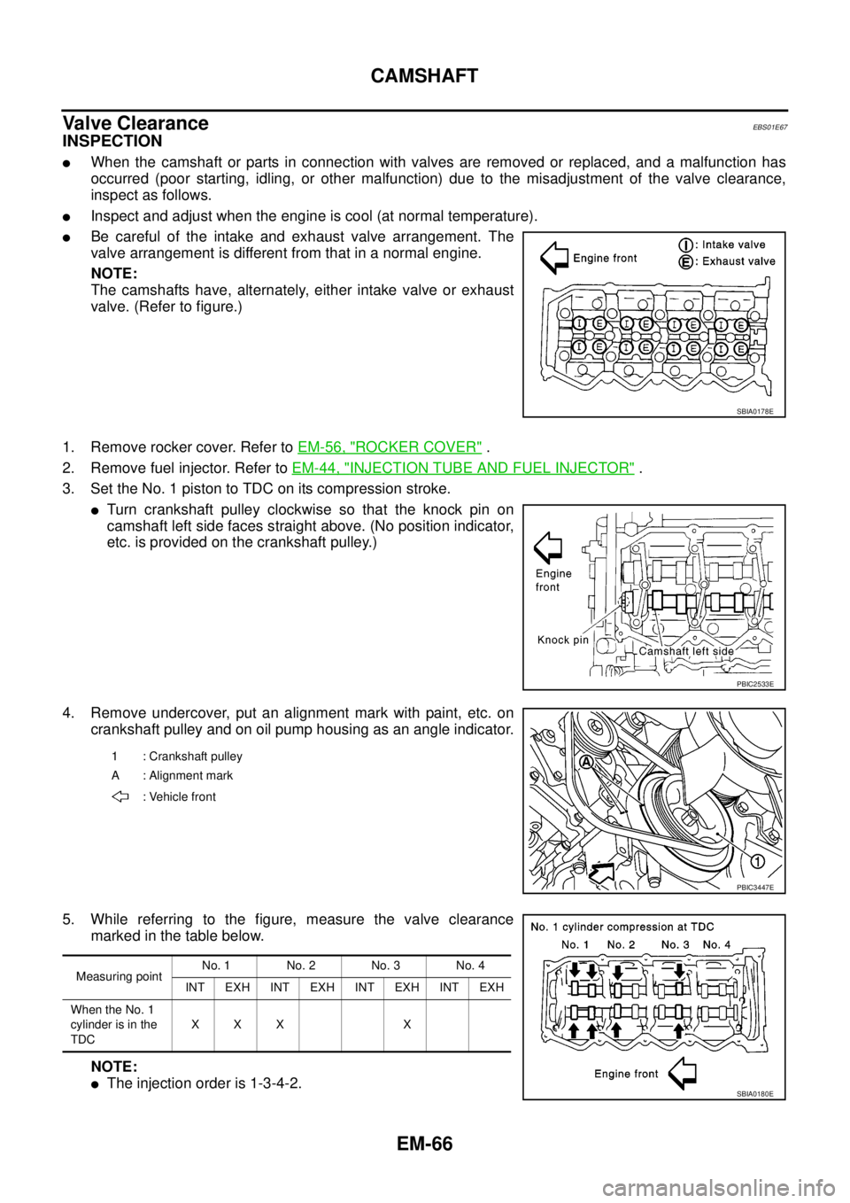
lBe careful of the intake and exhaust valve arrangement. The
valve arrangement is different from that in a normal engine.
NOTE:
The camshafts have, alternately, either intake valve or exhaust
valve. (Refer to figure.)
1. Remove rocker cover. Refer toEM-56, "
ROCKER COVER".
2. Remove fuel injector. Refer toEM-44, "
INJECTION TUBE AND FUEL INJECTOR".
3. Set the No. 1 piston to TDC on its compression stroke.
lTurn crankshaft pulley clockwise so that the knock pin on
camshaft left side faces straight above. (No position indicator,
etc. is provided on the crankshaft pulley.)
4. Remove undercover, put an alignment mark with paint, etc. on
crankshaft pulley and on oil pump housing as an angle indicator.
5. While referring to the figure, measure the valve clearance
marked in the table below.
NOTE:
lThe injection order is 1-3-4-2.
SBIA0178E
PBIC2533E
1 : Crankshaft pulley
A : Alignment mark
: Vehicle front
PBIC3447E
Measuring pointNo. 1 No. 2 No. 3 No. 4
INT EXH INT EXH INT EXH INT EXH
When the No. 1
cylinder is in the
TDCXXX X
SBIA0180E
Page 1449 of 3171

CAMSHAFT
EM-67
C
D
E
F
G
H
I
J
K
L
MA
EM
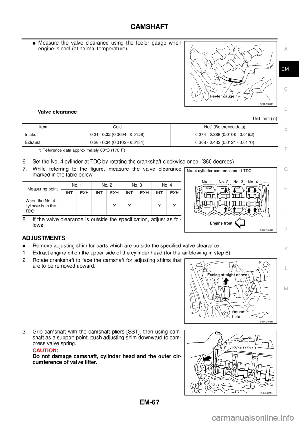
lMeasure the valve clearance using the feeler gauge when
engine is cool (at normal temperature).
Valve clearance:
Unit: mm (in)
*: Reference data approximately 80°C(176°F)
6. Set the No. 4 cylinder at TDC by rotating the crankshaft clockwise once. (360 degrees)
7. While referring to the figure, measure the valve clearance
marked in the table below.
8. If the valve clearance is outside the specification, adjust as fol-
lows.
ADJUSTMENTS
lRemove adjusting shim for parts which are outside the specified valve clearance.
1. Extract engine oil on the upper side of the cylinder head (for the air blowing in step 6).
2. Rotate crankshaft to face the camshaft for adjusting shims that
are to be removed upward.
3. Grip camshaft with the camshaft pliers [SST], then using cam-
shaft as a support point, push adjusting shim downward to com-
press valve spring.
CAUTION:
Do not damage camshaft, cylinder head and the outer cir-
cumference of valve lifter.
SBIA0181E
Item Cold Hot* (Reference data)
Intake 0.24 - 0.32 (0.0094 - 0.0126) 0.274 - 0.386 (0.0108 - 0.0152)
Exhaust 0.26 - 0.34 (0.0102 - 0.0134) 0.308 - 0.432 (0.0121 - 0.0170)
Measuring pointNo. 1 No. 2 No. 3 No. 4
INT EXH INT EXH INT EXH INT EXH
When the No. 4
cylinder is in the
TDCXX XX
SBIA0182E
SBIA0183E
PBIC2321E
Page 1454 of 3171
EM-72
OIL SEAL
Removal and Installation of Rear Oil Seal
EBS01EK9
REMOVAL
1. Remove transmission and transfer assembly. Refer toMT-16, "TRANSMISSION ASSEMBLY"(M/T mod-
els) andAT- 2 4 7 , "
TRANSMISSION ASSEMBLY"(A/T models).
2. Remove flywheel (M/T models) or drive plate (A/T models). Refer toEM-110, "
CYLINDER BLOCK".
3. Remove rear oil seal with a suitable tool.
CAUTION:
Be careful not to damage crankshaft and cylinder block.
INSTALLATION
1. Apply new engine oil to new rear oil seal joint surface and seal lip.
2. Install rear oil seal so that each seal lip is oriented as shown in
the figure.
lPress in rear oil seal (2) to rear oil seal retainer (1) as shown
in the figure.
lUsing the drift [100 mm (3.94 in) dia.] (A), press fit so that the
dimension is as specified in the figure.
lAvoid inclined fitting. Force fit perpendicularly.
3. Install in the reverse order of removal after this step.
SEM715A
PBIC4052E
Page 1456 of 3171
EM-74
SECONDARY TIMING CHAIN
lLoosen fixing bolts in reverse order of that shown in the figure
and remove them.
CAUTION:
lWhile front chain case is removed, cover openings to
prevent entry of foreign material into engine.
lDo not remove two mass dampers on the back of
cover.
4. Set the No. 1 piston to TDC on its compression stroke.
lTurn crankshaft pulley clockwise so that the alignment mark
(punched mark) on each camshaft sprocket is positioned as
showninthefigure.
lNo position indicator is provided on crankshaft pulley.
lWhen installing, color coded links on secondary timing
chain can be used as alignment marks. Marking may not
be necessary for removal; however, make alignment
marks as required because the alignment mark on fuel
pump sprocket may not be easy to see.
5. Remove chain tensioner.
a. Push the plunger of chain tensioner and keep it pressed with a
push pin.
JEM121G
SBIA0189E
SEM515G
JEM124G