2005 NISSAN NAVARA lock
[x] Cancel search: lockPage 926 of 3171
DI-16
COMBINATION METERS
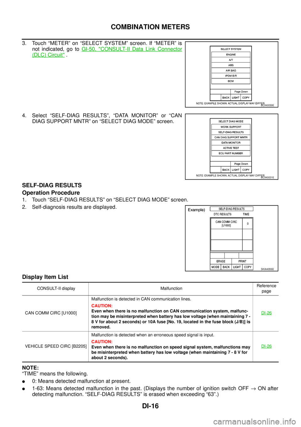
3. Touch “METER” on “SELECT SYSTEM” screen. If “METER” is
not indicated, go toGI-50, "
CONSULT-II Data Link Connector
(DLC) Circuit".
4. Select “SELF-DIAG RESULTS”, “DATA MONITOR” or “CAN
DIAG SUPPORT MNTR” on “SELECT DIAG MODE” screen.
SELF-DIAG RESULTS
Operation Procedure
1. Touch “SELF-DIAG RESULTS” on “SELECT DIAG MODE” screen.
2. Self-diagnosis results are displayed.
Display Item List
NOTE:
“TIME” means the following.
l0: Means detected malfunction at present.
l1-63: Means detected malfunction in the past. (Displays the number of ignition switch OFF®ON after
detecting malfunction. “SELF-DIAG RESULTS” is erased when exceeding “63”.)
BCIA0030E
BCIA0031E
SKIA4956E
CONSULT-II display MalfunctionReference
page
CAN COMM CIRC [U1000]Malfunction is detected in CAN communication lines.
CAUTION:
Even when there is no malfunction on CAN communication system, malfunc-
tion may be misinterpreted when battery has low voltage (when maintaining 7 -
8 V for about 2 seconds) or 10A fuse [No. 19, located in the fuse block (J/B)] is
removed.DI-26
VEHICLE SPEED CIRC [B2205]Malfunction is detected when an erroneous speed signal is input.
CAUTION:
Even when there is no malfunction on speed signal system, malfunctions may
be misinterpreted when battery has low voltage (when maintaining 7 - 8 V for
about 2 seconds).DI-26
Page 928 of 3171

DI-18
COMBINATION METERS
NOTE:
Some items are not available according to vehicle specification.
*: Monitor indicating “OFF” when brake warning lamp is on because of parking brake operation or low brake
fluid level continues.
Trouble DiagnosisEKS00L8M
HOW TO PERFORM TROUBLE DIAGNOSIS
1. Confirm the symptom or customer complaint.
2. Perform preliminary check. Refer toDI-19, "
PRELIMINARY CHECK".
3. According to the symptom chart, make sure of the symptom cause and repair or replace applicable parts.
Refer toDI-19, "
Symptom Chart".
4. Does the meter operate normally? If so, GO TO 5. If not, GO TO 2.
5. INSPECTION END
KEY G W/L [ON/OFF] X Indicates [ON/OFF] condition of KEY warning lamp (green).
KEY R W/L [ON/OFF] X Indicates [ON/OFF] condition of KEY warning lamp (red).
KEY KNOB W/L [ON/OFF] X Indicates [ON/OFF] condition of LOCK warning lamp.
M RANGE SW [ON/OFF] X X Indicates [ON/OFF] condition of manual mode range switch.
NM RANGE SW [ON/OFF] X XIndicates [ON/OFF] condition of except for manual mode range
switch.
AT SFT UP SW [ON/OFF] X X Indicates [ON/OFF] condition of A/T shift-up switch.
AT SFT DWN SW [ON/OFF] X X Indicates [ON/OFF] condition of A/T shift-down switch.
O/D OFF SW [ON/OFF] X Indicates [ON/OFF] condition of OD OFF switch.
BRAKE SW [ON/OFF] X Indicates [ON/OFF] condition of parking brake switch.
AT-M IND [ON/OFF] X X Indicates [ON/OFF] condition of A/T manual mode indicator.
AT-MGEAR[1,2,3,4,5] X XIndicates [1, 2, 3, 4, 5] condition of A/T manual mode gear
position.
P RANGE IND [ON/OFF] X X Indicates [ON/OFF] condition of A/T shift P range indicator.
R RANGE IND [ON/OFF] X X Indicates [ON/OFF] condition of A/T shift R range indicator.
N RANGE IND [ON/OFF] X X Indicates [ON/OFF] condition of A/T shift N range indicator.
D RANGE IND [ON/OFF] X X Indicates [ON/OFF] condition of A/T shift D range indicator.
4 RANGE IND [ON/OFF] X X Indicates [ON/OFF] condition of A/T shift 4 range indicator.
3 RANGE IND [ON/OFF] X X Indicates [ON/OFF] condition of A/T shift 3 range indicator.
2 RANGE IND [ON/OFF] X X Indicates [ON/OFF] condition of A/T shift 2 range indicator.
1 RANGE IND [ON/OFF] X X Indicates [ON/OFF] condition of A/T shift 1range indicator.
O/D OFF W/L [ON/OFF] X Indicates [ON/OFF] condition of OD OFF indicator lamp.
CRUISE IND [ON/OFF] X Indicates [ON/OFF] condition of CRUISE indicator lamp.
SET IND [ON/OFF] X Indicates [ON/OFF] condition of SET indicator lamp.
4WD LOCK SW [ON/OFF] X Indicates [ON/OFF] condition of 4WD LOCK switch.
4WD LOCK IND [ON/OFF] X Indicates [ON/OFF] condition of 4WD LOCK indicator lamp.
4WD W/L [ON/OFF] X Indicates [ON/OFF] condition of 4WD warning lamp.Display item [Unit]MAIN
SIGNALSSELECTION
FROM MENUContents
Page 961 of 3171
WARNING CHIME
DI-51
C
D
E
F
G
H
I
J
L
MA
B
DI
WARNING CHIMEPFP:24814
System DescriptionEKS00L9D
lBuzzer for warning chime system is installed in the combination meter.
lThe buzzer sounds at the following conditions:
–When combination meter receives buzzer output signal with CAN communication line
–When combination meter judges warning chime sound condition is found
POWER SUPPLY AND GROUND CIRCUIT
Power is supplied at all times
lthrough 50A fusible link (letterG, located in the fuse and fusible link box)
lto BCM terminal 57.
With ignition switch in the ON or START position, power is supplied
lthrough 10A fuse [No. 1, located in the fuse block (J/B)]
lto BCM terminal 3.
Ground is supplied
lto BCM terminal 55
lthrough grounds M21, M80 and M83.
LIGHT WARNING CHIME
With ignition switch in OFF or ACC position, driver's door open, and lighting switch in 1ST or 2ND position, the
light warning chime will sound.
lBCM detects ignition switch in OFF or ACC position, front door switch (driver side) ON, and lighting switch
in 1ST or 2ND position. And then transmits buzzer output signal (light warning chime) to combination
meter with CAN communication line.
lWhen combination meter receives buzzer output signal (light warning chime), it sounds the buzzer.
NOTE:
For further details of combination switch, refer toBCS-3, "
COMBINATION SWITCH READING FUNCTION".
KEY REMINDER WARNING CHIME
Key reminder chime sounds, at the same time, when key reminder system starts operating.
key reminder chime also sounds when the following three conditions are simultaneously met.
lKey is inserted in the ignition key cylinder
lDriver¢s door is opened
lThe setting of driver¢s door lock knob is “LOCK”
For information regarding key reminder system, refer toBL-21, "
POWER DOOR LOCK SYSTEM".
LOW-FUEL WARNING CHIME
Low-fuel warning chime sounds, when low-fuel warning lamp is turned ON.
Combination meter sounds warning chime three times when low-fuel warning lamp turns ON.
Page 990 of 3171

EC-10
PRECAUTIONS
PRECAUTIONS
PFP:00001
Precautions for Supplemental Restraint System (SRS) “AIR BAG” and “SEAT
BELT PRE-TENSIONER”
EBS01KC5
The Supplemental Restraint System such as “AIR BAG” and “SEAT BELT PRE-TENSIONER”, used along
with a front seat belt, helps to reduce the risk or severity of injury to the driver and front passenger for certain
types of collision. Information necessary to service the system safely is included in the SRS and SB section of
this Service Manual.
WARNING:
lTo avoid rendering the SRS inoperative, which could increase the risk of personal injury or death
in the event of a collision which would result in air bag inflation, all maintenance must be per-
formed by an authorized NISSAN/INFINITI dealer.
lImproper maintenance, including incorrect removal and installation of the SRS, can lead to per-
sonal injury caused by unintentional activation of the system. For removal of Spiral Cable and Air
Bag Module, see the SRS section.
lDo not use electrical test equipment on any circuit related to the SRS unless instructed to in this
Service Manual. SRS wiring harnesses can be identified by yellow and/or orange harnesses or
harness connectors.
On Board Diagnostic (OBD) System of EngineEBS01KC6
The ECM has an on board diagnostic system. It will light up the malfunction indicator (MI) to warn the driver of
a malfunction causing emission deterioration.
CAUTION:
lBe sure to turn the ignition switch OFF and disconnect the battery negative cable before any
repair or inspection work. The open/short circuit of related switches, sensors, solenoid valves,
etc. will cause the MI to light up.
lBe sure to connect and lock the connectors securely after work. A loose (unlocked) connector will
cause the MI to light up due to the open circuit. (Be sure the connector is free from water, grease,
dirt, bent terminals, etc.)
lCertain systems and components, especially those related to OBD, may use a new style slide-
locking type harness connector. For description and how to disconnect, refer toPG-75, "
HAR-
NESS CONNECTOR".
lBe sure to route and secure the harnesses properly after work. The interference of the harness
with a bracket, etc. may cause the MI to light up due to the short circuit.
lBe sure to connect rubber tubes properly after work. A misconnected or disconnected rubber tube
may cause the MI to light up due to the malfunction of the fuel system, etc.
lBe sure to erase the unnecessary malfunction information (repairs completed) from the ECM
before returning the vehicle to the customer.
PrecautionsEBS01KC7
lAlways use a 12 volt battery as power source.
lDo not attempt to disconnect battery cables while engine is
running.
lBefore connecting or disconnecting the ECM harness con-
nector, turn ignition switch OFF and disconnect battery
negative cable. Failure to do so may damage the ECM
because battery voltage is applied to ECM even if ignition
switch is turned off.
lBefore removing parts, turn ignition switch OFF and then
disconnect battery negative cable.
SEF289H
Page 1009 of 3171
ON BOARD DIAGNOSTIC (OBD) SYSTEM
EC-29
C
D
E
F
G
H
I
J
K
L
MA
EC
HOWTOSWITCHDIAGNOSTICTESTMODE
NOTE:
lIt is better to count the time accurately with a clock.
lIt is impossible to switch the diagnostic mode when an accelerator pedal position sensor circuit
has a malfunction.
lAlways ECM returns to Diagnostic Test Mode I after ignition switch is turned OFF.
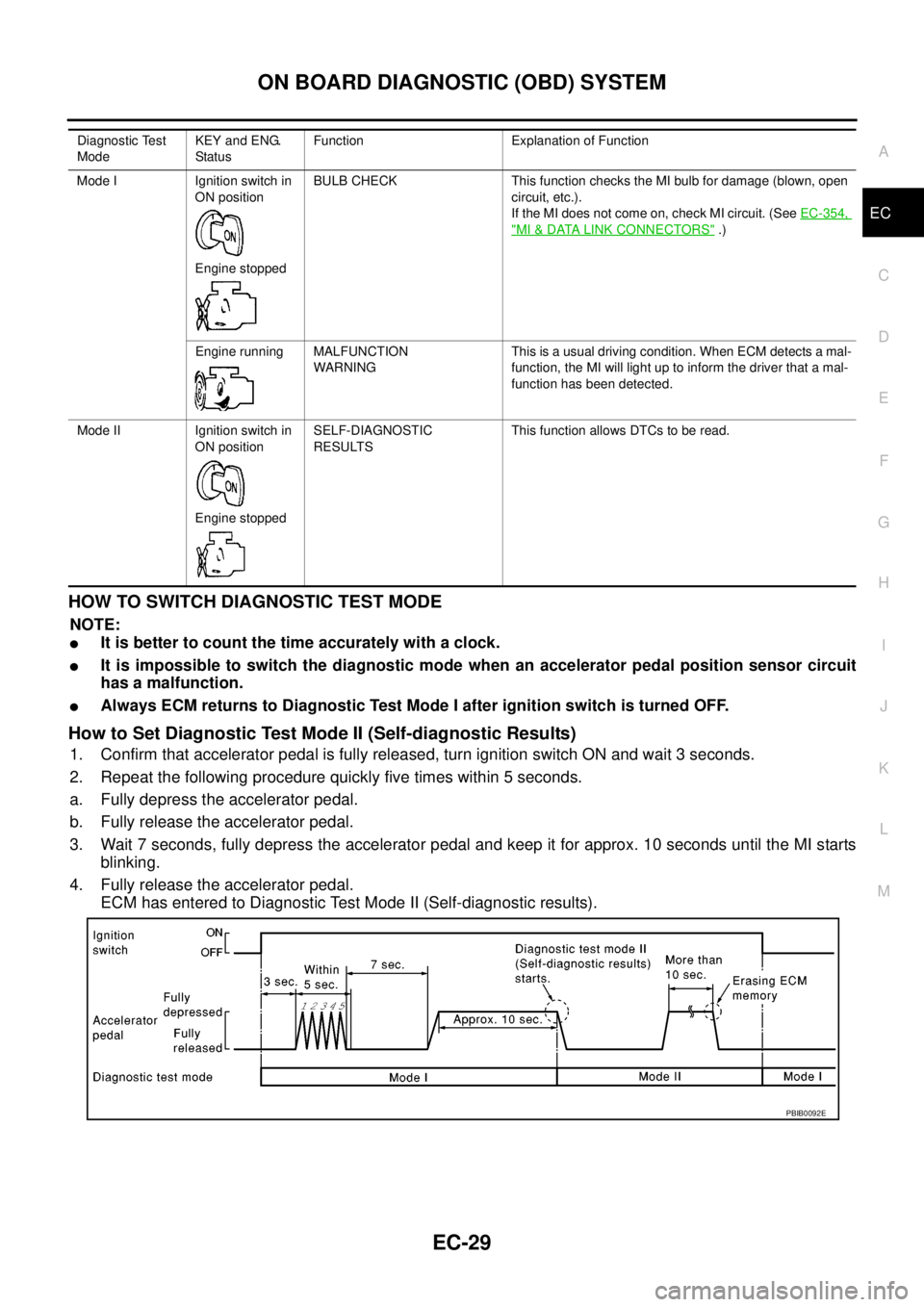
How to Set Diagnostic Test Mode II (Self-diagnostic Results)
1. Confirm that accelerator pedal is fully released, turn ignition switch ON and wait 3 seconds.
2. Repeat the following procedure quickly five times within 5 seconds.
a. Fully depress the accelerator pedal.
b. Fully release the accelerator pedal.
3. Wait 7 seconds, fully depress the accelerator pedal and keep it for approx. 10 seconds until the MI starts
blinking.
4. Fully release the accelerator pedal.
ECM has entered to Diagnostic Test Mode II (Self-diagnostic results).
Diagnostic Test
ModeKEY and ENG.
Statu sFunction Explanation of Function
Mode I Ignition switch in
ON position
Engine stoppedBULB CHECK This function checks the MI bulb for damage (blown, open
circuit, etc.).
If the MI does not come on, check MI circuit. (SeeEC-354,
"MI&DATA LINK CONNECTORS".)
Engine running MALFUNCTION
WARNINGThis is a usual driving condition. When ECM detects a mal-
function, the MI will light up to inform the driver that a mal-
function has been detected.
Mode II Ignition switch in
ON position
Engine stoppedSELF-DIAGNOSTIC
RESULTSThis function allows DTCs to be read.
PBIB0092E
Page 1053 of 3171
POWER SUPPLY AND GROUND CIRCUIT
EC-73
C
D
E
F
G
H
I
J
K
L
MA
EC
Diagnostic ProcedureEBS01KD8
1.INSPECTION START
Start engine.
Is engine running?
Ye s o r N o
Ye s > > G O T O 7 .
No >> GO TO 2.
2.CHECK ECM POWER SUPPLY CIRCUIT-I
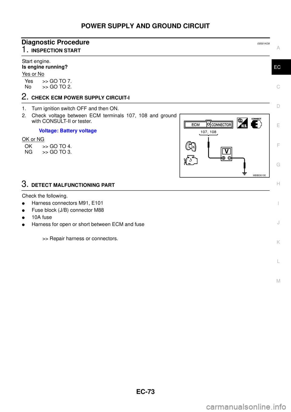
1. Turn ignition switch OFF and then ON.
2. Check voltage between ECM terminals 107, 108 and ground
with CONSULT-II or tester.
OK or NG
OK >> GO TO 4.
NG >> GO TO 3.
3.DETECT MALFUNCTIONING PART
Check the following.
lHarness connectors M91, E101
lFuse block (J/B) connector M88
l10A fuse
lHarness for open or short between ECM and fuse
>> Repair harness or connectors. Voltage: Battery voltage
MBIB0610E
Page 1120 of 3171
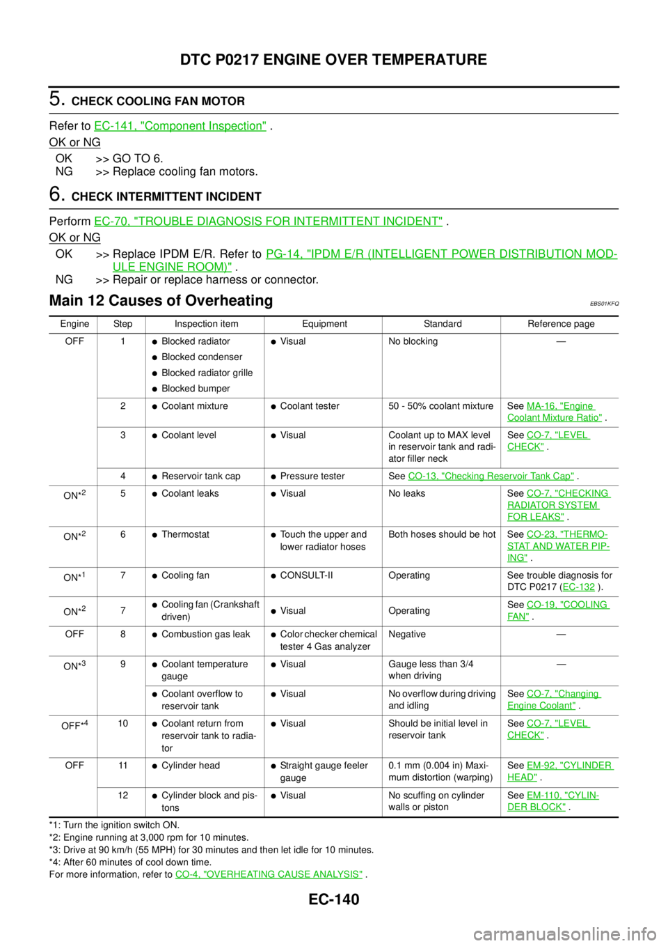
EC-140
DTC P0217 ENGINE OVER TEMPERATURE
5.CHECK COOLING FAN MOTOR
Refer toEC-141, "
Component Inspection".
OK or NG
OK >> GO TO 6.
NG >> Replace cooling fan motors.
6.CHECK INTERMITTENT INCIDENT
PerformEC-70, "
TROUBLE DIAGNOSIS FOR INTERMITTENT INCIDENT".
OK or NG
OK >> Replace IPDM E/R. Refer toPG-14, "IPDM E/R (INTELLIGENT POWER DISTRIBUTION MOD-
ULE ENGINE ROOM)".
NG >> Repair or replace harness or connector.
Main 12 Causes of OverheatingEBS01KFQ
*1: Turn the ignition switch ON.
*2: Engine running at 3,000 rpm for 10 minutes.
*3: Drive at 90 km/h (55 MPH) for 30 minutes and then let idle for 10 minutes.
*4: After 60 minutes of cool down time.
For more information, refer toCO-4, "
OVERHEATING CAUSE ANALYSIS". Engine Step Inspection item Equipment Standard Reference page
OFF 1
lBlocked radiator
lBlocked condenser
lBlocked radiator grille
lBlocked bumper
lVisual No blocking —
2
lCoolant mixturelCoolant tester 50 - 50% coolant mixture SeeMA-16, "Engine
Coolant Mixture Ratio".
3
lCoolant levellVisual Coolant up to MAX level
in reservoir tank and radi-
ator filler neckSeeCO-7, "LEVEL
CHECK".
4
lReservoir tank caplPressure tester SeeCO-13, "Checking Reservoir Tank Cap".
ON*
25lCoolant leakslVisual No leaks SeeCO-7, "CHECKING
RADIATOR SYSTEM
FOR LEAKS".
ON*
26lThermostatlTouch the upper and
lower radiator hosesBoth hoses should be hot SeeCO-23, "THERMO-
STAT AND WATER PIP-
ING".
ON*
17lCooling fanlCONSULT-II Operating See trouble diagnosis for
DTC P0217 (EC-132
).
ON*
27lCooling fan (Crankshaft
driven)lVisual OperatingSeeCO-19, "COOLING
FA N".
OFF 8
lCombustion gas leaklColor checker chemical
tester 4 Gas analyzerNegative —
ON*
39lCoolant temperature
gaugelVisual Gauge less than 3/4
when driving—
lCoolant overflow to
reservoir tanklVisual No overflow during driving
and idlingSeeCO-7, "Changing
Engine Coolant".
OFF*
410lCoolant return from
reservoir tank to radia-
torlVisual Should be initial level in
reservoir tankSeeCO-7, "LEVEL
CHECK".
OFF 11
lCylinder headlStraight gauge feeler
gauge0.1 mm (0.004 in) Maxi-
mum distortion (warping)SeeEM-92, "CYLINDER
HEAD".
12
lCylinder block and pis-
tonslVisual No scuffing on cylinder
walls or pistonSeeEM-110, "CYLIN-
DER BLOCK".
Page 1139 of 3171
DTC P0335 CKP SENSOR
EC-159
C
D
E
F
G
H
I
J
K
L
MA
EC
DTC P0335 CKP SENSORPFP:23731
DescriptionEBS01KGJ
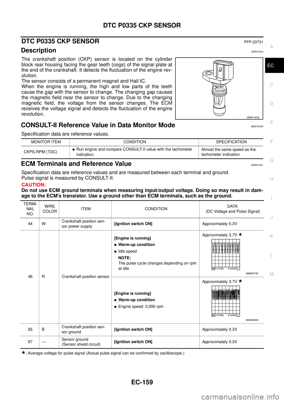
The crankshaft position (CKP) sensor is located on the cylinder
block rear housing facing the gear teeth (cogs) of the signal plate at
the end of the crankshaft. It detects the fluctuation of the engine rev-
olution.
The sensor consists of a permanent magnet and Hall IC.
When the engine is running, the high and low parts of the teeth
cause the gap with the sensor to change. The changing gap causes
the magnetic field near the sensor to change. Due to the changing
magnetic field, the voltage from the sensor changes. The ECM
receives the voltage signal and detects the fluctuation of the engine
revolution.
CONSULT-II Reference Value in Data Monitor ModeEBS01KGK
Specification data are reference values.
ECM Terminals and Reference ValueEBS01KGL
Specification data are reference values and are measured between each terminal and ground.
Pulse signal is measured by CONSULT-II.
CAUTION:
Do not use ECM ground terminals when measuring input/output voltage. Doing so may result in dam-
age to the ECM's transistor. Use a ground other than ECM terminals, such as the ground.
: Average voltage for pulse signal (Actual pulse signal can be confirmed by oscilloscope.)
MBIB1323E
MONITOR ITEM CONDITION SPECIFICATION
CKPS-RPM (TDC)
lRun engine and compare CONSULT-II value with the tachometer
indication.Almost the same speed as the
tachometer indication
TERMI-
NAL
NO.WIRE
COLORITEM CONDITIONDATA
(DC Voltage and Pulse Signal)
44 WCrankshaft position sen-
sor power supply[Ignition switch ON]Approximately 5.3V
46 R Crankshaft position sensor[Engine is running]
lWarm-up condition
lIdle speed
NOTE:
The pulse cycle changes depending on rpm
at idleApproximately 3.7V
[Engine is running]
lWarm-up condition
lEngine speed: 2,000 rpmApproximately 3.7V
65 BCrankshaft position sen-
sor ground[Ignition switch ON]Approximately 0.3V
67 —Sensor ground
(Sensor shield circuit)[Ignition switch ON]Approximately 0.3V
MBIB0879E
MBIB0880E