Page 827 of 3171
![NISSAN NAVARA 2005 Repair Workshop Manual SYSTEM DESCRIPTION
BRC-5
[ABS]
C
D
E
G
H
I
J
K
L
MA
B
BRC
SYSTEM DESCRIPTIONPFP:00000
System DiagramEFS005TJ
FunctionsEFS005TK
ABS
lThe Anti-Lock Brake System is a function that detects wheel revoluti NISSAN NAVARA 2005 Repair Workshop Manual SYSTEM DESCRIPTION
BRC-5
[ABS]
C
D
E
G
H
I
J
K
L
MA
B
BRC
SYSTEM DESCRIPTIONPFP:00000
System DiagramEFS005TJ
FunctionsEFS005TK
ABS
lThe Anti-Lock Brake System is a function that detects wheel revoluti](/manual-img/5/57362/w960_57362-826.png)
SYSTEM DESCRIPTION
BRC-5
[ABS]
C
D
E
G
H
I
J
K
L
MA
B
BRC
SYSTEM DESCRIPTIONPFP:00000
System DiagramEFS005TJ
FunctionsEFS005TK
ABS
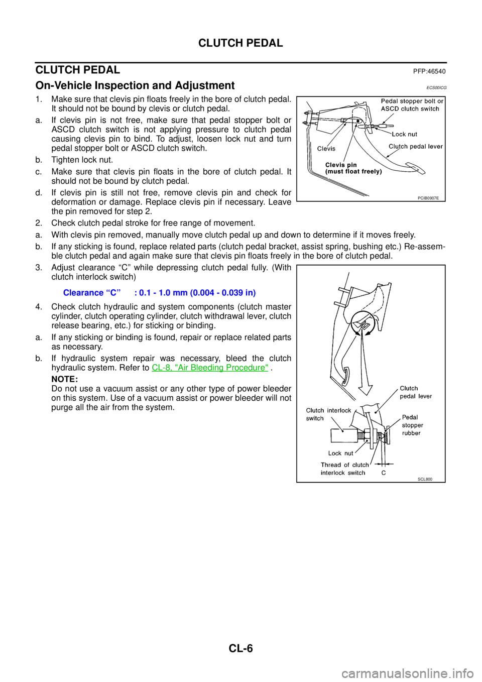
lThe Anti-Lock Brake System is a function that detects wheel revolution while braking, and it improves
handling stability during sudden braking by electrically preventing 4 wheels lock. Maneuverability is also
improved for avoiding obstacles.
lElectrical system diagnosis by CONSULT-II is available.
EBD
lElectronic Brake Distributor is a function that detects subtle slippages between the front and rear tyre dur-
ing braking, and it improves handling stability by electrically controlling the brake fluid pressure which
results in reduced rear tyre slippage.
lElectrical system diagnosis by CONSULT-II is available.
Operation That Is Not “System Error”EFS005TL
ABS
lWhen starting engine or just after starting vehicle, brake pedal may vibrate or the motor operating noise
may be heard from engine room. This is a normal states of the operation check.
lDuring ABS operation, brake pedal lightly vibrates and a mechanical noise may be heard. This is normal.
lStopping distance may be longer than that of vehicles without ABS when vehicle drives on rough, gravel,
or snow-covered (fresh, deep snow) roads.
Fail-Safe FunctionEFS005TM
ABS, EBD SYSTEM
In case of electrical malfunction with ABS, ABS warning lamp will turn on. In case of electrical incidents with
EBD, brake warning lamp and ABS warning lamp will turn on. Simultaneously, ABS become one of following
conditions of Fail-Safe function.
1. For ABS malfunction, only EBD is activated and condition of vehicle is same condition of vehicles without
ABS system.
NOTE:
ABS self-diagnosis sound may be heard.That is a normal condition because a self-diagnosis for “Ignition
switch ON” and “The first starting” are being performed.
2. For EBD malfunction, EBD and ABS become inoperative, and condition of vehicle is same as condition of
vehicles without ABS, EBD system.
SFIA3001E
Page 860 of 3171
BRC-38
[ABS]
WHEEL SENSORS
REMOVAL
Pay attention to the following when removing wheel sensor.
CAUTION:
lAs much as possible, avoid rotating wheel sensor when removing it. Pull wheel sensors out with-
out pulling on sensor harness.
lTake care to avoid damaging wheel sensor edges or rotor teeth. Remove wheel sensor first before
removing front or rear wheel hub. This is to avoid damage to wheel sensor wiring and loss of sen-
sor function.
INSTALLATION
Pay attention to the following when installing wheel sensor. Tighten installation bolts and nuts to the specified
torques.
lWhen installing, make sure there is no foreign material such as iron chips on and in the mounting hole of
the wheel sensor. Make sure no foreign material has been caught in the sensor rotor. Remove any foreign
material and clean the mount.
lWhen installing wheel sensor, be sure to press rubber grommets in until they lock at locations shown
above in figure. When installed, harness must not be twisted.
Page 863 of 3171
ACTUATOR AND ELECTRIC UNIT (ASSEMBLY)
BRC-41
[ABS]
C
D
E
G
H
I
J
K
L
MA
B
BRC
INSTALLATION
Installation is the reverse order of removal.
NOTE:
After installing harness connector in the ABS actuator and electric unit (control unit), make sure connector is
securely locked.
Page 870 of 3171

CL-6
CLUTCH PEDAL
CLUTCH PEDAL
PFP:46540
On-Vehicle Inspection and AdjustmentECS00ICG
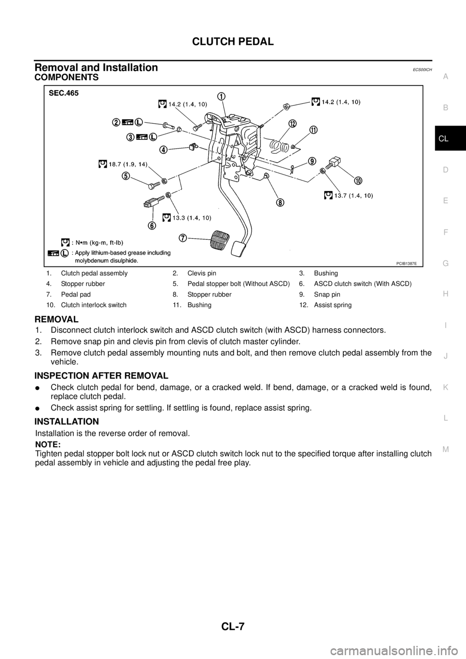
1. Make sure that clevis pin floats freely in the bore of clutch pedal.
It should not be bound by clevis or clutch pedal.
a. If clevis pin is not free, make sure that pedal stopper bolt or
ASCD clutch switch is not applying pressure to clutch pedal
causing clevis pin to bind. To adjust, loosen lock nut and turn
pedal stopper bolt or ASCD clutch switch.
b. Tighten lock nut.
c. Make sure that clevis pin floats in the bore of clutch pedal. It
should not be bound by clutch pedal.
d. If clevis pin is still not free, remove clevis pin and check for
deformation or damage. Replace clevis pin if necessary. Leave
the pin removed for step 2.
2. Check clutch pedal stroke for free range of movement.
a. With clevis pin removed, manually move clutch pedal up and down to determine if it moves freely.
b. If any sticking is found, replace related parts (clutch pedal bracket, assist spring, bushing etc.) Re-assem-
ble clutch pedal and again make sure that clevis pin floats freely in the bore of clutch pedal.
3. Adjust clearance “C” while depressing clutch pedal fully. (With
clutch interlock switch)
4. Check clutch hydraulic and system components (clutch master
cylinder, clutch operating cylinder, clutch withdrawal lever, clutch
release bearing, etc.) for sticking or binding.
a. If any sticking or binding is found, repair or replace related parts
as necessary.
b. If hydraulic system repair was necessary, bleed the clutch
hydraulic system. Refer toCL-8, "
Air Bleeding Procedure".
NOTE:
Do not use a vacuum assist or any other type of power bleeder
on this system. Use of a vacuum assist or power bleeder will not
purge all the air from the system.Clearance “C” : 0.1 - 1.0 mm (0.004 - 0.039 in)
PCIB0907E
SCL800
Page 871 of 3171

CLUTCH PEDAL
CL-7
D
E
F
G
H
I
J
K
L
MA
B
CL
Removal and InstallationECS00ICH
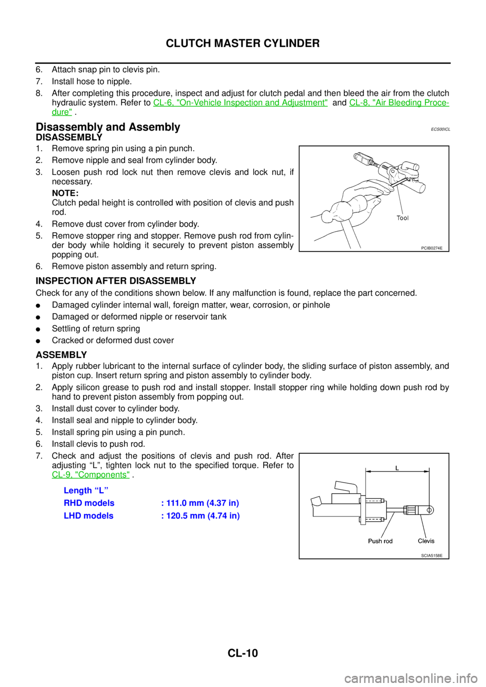
COMPONENTS
REMOVAL
1. Disconnect clutch interlock switch and ASCD clutch switch (with ASCD) harness connectors.
2. Remove snap pin and clevis pin from clevis of clutch master cylinder.
3. Remove clutch pedal assembly mounting nuts and bolt, and then remove clutch pedal assembly from the
vehicle.
INSPECTION AFTER REMOVAL
lCheck clutch pedal for bend, damage, or a cracked weld. If bend, damage, or a cracked weld is found,
replace clutch pedal.
lCheck assist spring for settling. If settling is found, replace assist spring.
INSTALLATION
Installation is the reverse order of removal.
NOTE:
Tighten pedal stopper bolt lock nut or ASCD clutch switch lock nut to the specified torque after installing clutch
pedal assembly in vehicle and adjusting the pedal free play.
1. Clutch pedal assembly 2. Clevis pin 3. Bushing
4. Stopper rubber 5. Pedal stopper bolt (Without ASCD) 6. ASCD clutch switch (With ASCD)
7. Pedal pad 8. Stopper rubber 9. Snap pin
10. Clutch interlock switch 11. Bushing 12. Assist spring
PCIB1387E
Page 874 of 3171

CL-10
CLUTCH MASTER CYLINDER
6. Attach snap pin to clevis pin.
7. Install hose to nipple.
8. After completing this procedure, inspect and adjust for clutch pedal and then bleed the air from the clutch
hydraulic system. Refer toCL-6, "
On-Vehicle Inspection and Adjustment"andCL-8, "Air Bleeding Proce-
dure".
Disassembly and AssemblyECS00ICL
DISASSEMBLY
1. Remove spring pin using a pin punch.
2. Remove nipple and seal from cylinder body.
3. Loosen push rod lock nut then remove clevis and lock nut, if
necessary.
NOTE:
Clutch pedal height is controlled with position of clevis and push
rod.
4. Remove dust cover from cylinder body.
5. Remove stopper ring and stopper. Remove push rod from cylin-
der body while holding it securely to prevent piston assembly
popping out.
6. Remove piston assembly and return spring.
INSPECTION AFTER DISASSEMBLY
Check for any of the conditions shown below. If any malfunction is found, replace the part concerned.
lDamaged cylinder internal wall, foreign matter, wear, corrosion, or pinhole
lDamaged or deformed nipple or reservoir tank
lSettling of return spring
lCracked or deformed dust cover
ASSEMBLY
1. Apply rubber lubricant to the internal surface of cylinder body, the sliding surface of piston assembly, and
piston cup. Insert return spring and piston assembly to cylinder body.
2. Apply silicon grease to push rod and install stopper. Install stopper ring while holding down push rod by
hand to prevent piston assembly from popping out.
3. Install dust cover to cylinder body.
4. Install seal and nipple to cylinder body.
5. Install spring pin using a pin punch.
6. Install clevis to push rod.
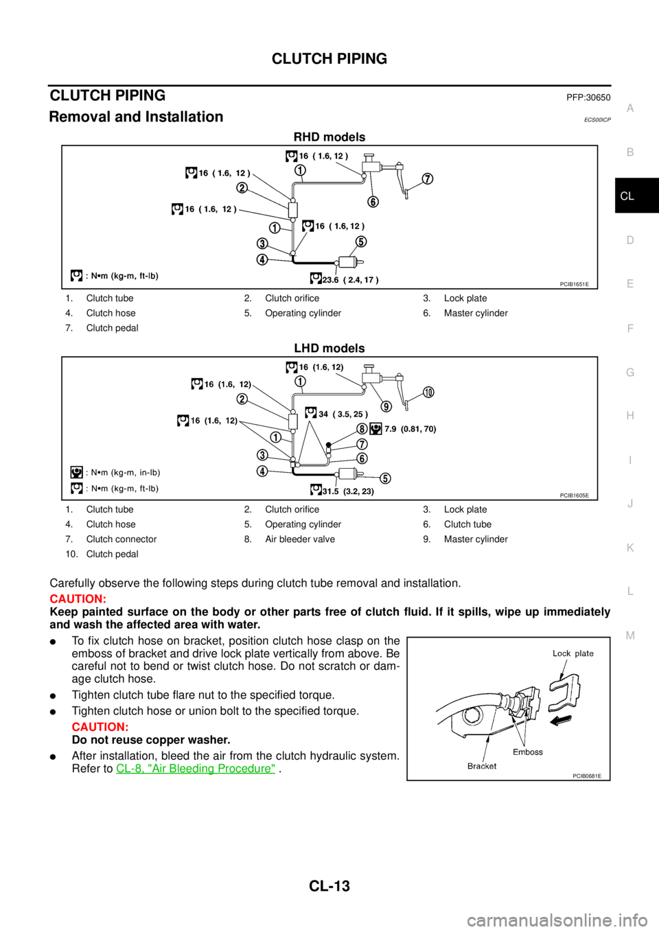
7. Check and adjust the positions of clevis and push rod. After
adjusting “L”, tighten lock nut to the specified torque. Refer to
CL-9, "
Components".
PCIB0274E
Length “L”
RHD models : 111.0 mm (4.37 in)
LHD models : 120.5 mm (4.74 in)
SCIA5158E
Page 877 of 3171

CLUTCH PIPING
CL-13
D
E
F
G
H
I
J
K
L
MA
B
CL
CLUTCH PIPINGPFP:30650
Removal and InstallationECS00ICP
RHD models
LHD models
Carefully observe the following steps during clutch tube removal and installation.
CAUTION:
Keep painted surface on the body or other parts free of clutch fluid. If it spills, wipe up immediately
and wash the affected area with water.
lTo fix clutch hose on bracket, position clutch hose clasp on the
emboss of bracket and drive lock plate vertically from above. Be
careful not to bend or twist clutch hose. Do not scratch or dam-
age clutch hose.
lTighten clutch tube flare nut to the specified torque.
lTighten clutch hose or union bolt to the specified torque.
CAUTION:
Do not reuse copper washer.
lAfter installation, bleed the air from the clutch hydraulic system.
Refer toCL-8, "
Air Bleeding Procedure".
PCIB1651E
1. Clutch tube 2. Clutch orifice 3. Lock plate
4. Clutch hose 5. Operating cylinder 6. Master cylinder
7. Clutch pedal
PCIB1605E
1. Clutch tube 2. Clutch orifice 3. Lock plate
4. Clutch hose 5. Operating cylinder 6. Clutch tube
7. Clutch connector 8. Air bleeder valve 9. Master cylinder
10. Clutch pedal
PCIB0681E
Page 884 of 3171
CL-20
SERVICE DATA AND SPECIFICATIONS (SDS)
SERVICE DATA AND SPECIFICATIONS (SDS)
PFP:00030
Clutch Control SystemECS00ICS
Clutch Master CylinderECS00ICT
Clutch Operating CylinderECS00ICU
Clutch DiscECS00ICV
Clutch CoverECS00ICW
Clutch PedalECS00ICX
Type of clutch controlHydraulic
Inner diameter15.87 mm (5/8 in)
Inner diameter19.05 mm (3/4 in)
Facing size (outer dia. x inner dia. x thickness) 240 mm´160 mm´3.15 mm (9.45 in´6.30 in´0.1240 in)
Wear limit of facing surface to rivet head 0.3 mm (0.012 in)
Runout limit/diameter of the area to be measured 1.0 mm (0.039 in) / 230 mm (9.06 in) dia.
Maximum spline backlash (at outer edge of disc) 1.0 mm (0.039 in)
Set-load9,810 N (1,000 kg, 2,205 lb)
Diaphragm spring lever height 39.0 - 41.0 mm (1.535 - 1.614 in)
Uneven limit diaphragm spring toe height 0.7 mm (0.028 in) or less
Clearance²C²between pedal stopper rubber and clutch interlock
switch threaded while clutch pedal is fully depressed0.1 - 1.0 mm (0.004 - 0.039 in)