Page 773 of 3171
CAB AND REAR BODY
BL-189
C
D
E
F
G
H
J
K
L
MA
B
BL
CAB AND REAR BODYPFP:93020
Body Mounting (King Cab)EIS00DI6
lWhen removing, be sure to replace bolts and nuts (sealant applied bolts or self-lock nuts are used for all
mounting).
lUnless otherwise noted, the bushings and insulators have paint marks that are to be installed facing out-
ward.
1. Cab mounting insulator (1st) 2. Cab mounting insulator (2nd) 3. Cab mounting insulator (3rd)
MIIB0935E
Page 774 of 3171
BL-190
CAB AND REAR BODY
Body Mounting (Double Cab)
EIS00DWV
lWhen removing, be sure to replace bolts and nuts (sealant applied bolts or self-lock nuts are used for all
mounting).
lUnless otherwise noted, the bushings and insulators have paint marks that are to be installed facing out-
ward.
1. Cab mounting insulator (1st) 2. Cab mounting insulator (2nd) 3. Cab mounting insulator (3rd)
4. Cab mounting insulator (4th)
MIIB0936E
Page 793 of 3171
BRAKE PEDAL
BR-7
C
D
E
G
H
I
J
K
L
MA
B
BR
ADJUSTMENT
1. Loosen the stop lamp switch and by turning it counterclockwise
by 45°.
2. Loosen lock nut (A) on the input rod, then turn input rod to adjust
the pedal to specified height, and tighten lock nut (A).
CAUTION:
Make sure the threaded end of the input rod stays inside the
clevis.
3. With the pedal pulled and held by hand, press the stop lamp
switch and until its threaded end contacts the stopper.
4. With the threaded end of the stop lamp switch and contacting
the stopper, turn the switch clockwise by 45°to secure.
CAUTION:
Make sure that the clearance (C) between the bracket and
threaded end of the stop lamp switch and are within the
standard.
5. Check the pedal play.
CAUTION:
Make sure that the stop lamp goes off when the pedal is
released.
6. Start the engine to check the brake pedal depressed height.
Refer toBR-6, "
Inspection and Adjustment". Lock nut (A)
:18.7 N·m (1.9 kg-m, 14 ft-lb)
PFIA0436E
Page 795 of 3171
BRAKE PEDAL
BR-9
C
D
E
G
H
I
J
K
L
MA
B
BR
INSPECTION AFTER REMOVAL
lCheck brake pedal upper rivet for deformation.
lMake sure that the lapping length of sub-bracket and slide plate
is at least 4 mm (0.16 in).
lCheck brake pedal for bend, damage, and cracks on the welded
parts.
lReplace brake pedal assembly if any non-standard condition is
detected.
lCheck clevis pin and plastic stopper for damage and deforma-
tion. Replace clevis pin if there are.
INSTALLATION
Installation is in the reverse order of the removal. Tightening torques for brake pedal assembly mounting nut
and bolt are referred toBR-8, "
COMPONENTS". Tightening torque for lock nut (A) is referred to Refer toBR-
7, "ADJUSTMENT".
lAfter installing the brake pedal assembly to the vehicle, adjust the brake pedal. Refer toBR-6, "Inspection
and Adjustment".
SFIA2866E
SBR997
Page 799 of 3171

BRAKE TUBE AND HOSE
BR-13
C
D
E
G
H
I
J
K
L
MA
B
BR
CAUTION:
lAll brake tubes and hoses must be free from excessive bending, twisting and pulling.
lMake sure that there is no interference with other parts when turning steering both clockwise and
counterclockwise.
lBrake tube and hose is an important safety part. Always disassemble the parts and retighten their
fittings, if a brake fluid leak is detected. Replace applicable part with a new one, if damaged part is
detected.
lBe careful not to splash brake fluid on painted areas; it may cause paint damage. If brake fluid is
splashed on painted surfaces of body, immediately wipe off them and wash it away with water.
lDo not bend or twist brake hose sharply, or strongly pull it.
lCover the open end of brake tube and hoses when disconnecting to prevent entrance of dirt.
lRefill with new brake fluid “DOT 3” or “DOT 4”.
lNever reuse drained brake fluid.
Removal and Installation of Front Brake Tube and Brake HoseEFS005SM
REMOVAL
1. Drain brake fluid. Refer toBR-10, "Drain and Refill".
2. Using a flare nut wrench, disconnect brake tube from brake hose.
3. Remove union bolt and remove brake hose from caliper assembly.
4. Remove lock plate and remove brake hose from vehicle.
INSTALLATION
1. Assemble the union bolt and copper washers to the brake hose.
2. Insert brake hose by aligning with the protrusion on caliper
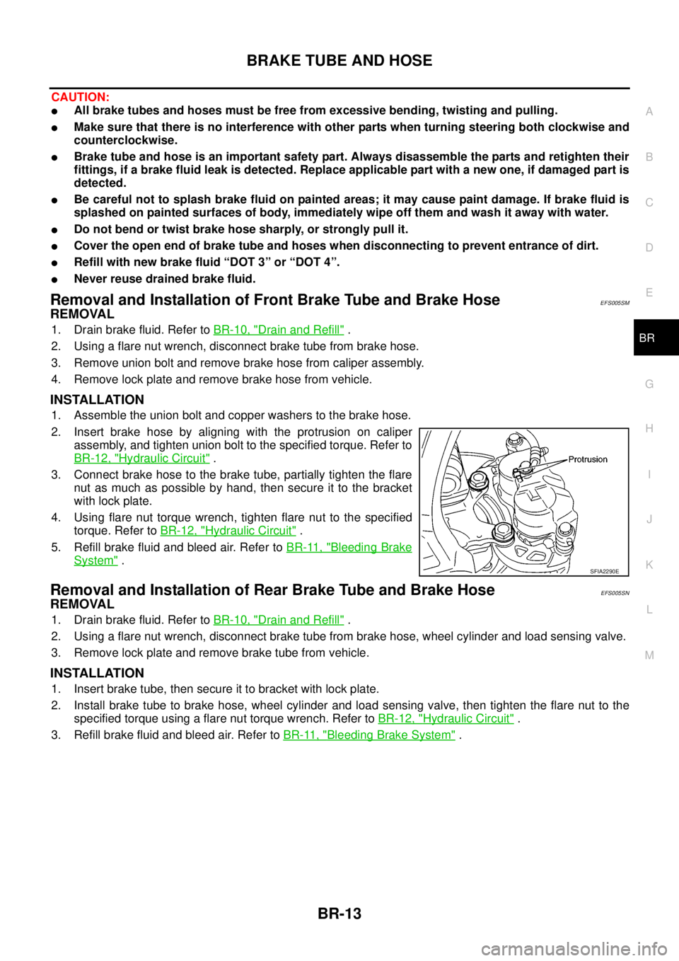
assembly, and tighten union bolt to the specified torque. Refer to
BR-12, "
Hydraulic Circuit".
3. Connect brake hose to the brake tube, partially tighten the flare
nut as much as possible by hand, then secure it to the bracket
with lock plate.
4. Using flare nut torque wrench, tighten flare nut to the specified
torque. Refer toBR-12, "
Hydraulic Circuit".
5. Refill brake fluid and bleed air. Refer toBR-11, "
Bleeding Brake
System".
Removal and Installation of Rear Brake Tube and Brake HoseEFS005SN
REMOVAL
1. Drain brake fluid. Refer toBR-10, "Drain and Refill".
2. Using a flare nut wrench, disconnect brake tube from brake hose, wheel cylinder and load sensing valve.
3. Remove lock plate and remove brake tube from vehicle.
INSTALLATION
1. Insert brake tube, then secure it to bracket with lock plate.
2. Install brake tube to brake hose, wheel cylinder and load sensing valve, then tighten the flare nut to the
specified torque using a flare nut torque wrench. Refer toBR-12, "
Hydraulic Circuit".
3. Refill brake fluid and bleed air. Refer toBR-11, "
Bleeding Brake System".
SFIA2290E
Page 806 of 3171

BR-20
BRAKE BOOSTER
Removal and Installation
EFS005SU
COMPONENTS
REMOVAL
CAUTION:
lBe careful not to deform or bend brake tube while removing and installing the brake booster.
lReplace clevis pin if it is damaged.
lBe careful not to damage brake booster stud bolt threads. If brake booster is tilted or inclined dur-
ing installation, the dash panel may damage the threads.
1. Remove ABS actuator and electric unit (control unit). Refer toBRC-40, "
Removal and Installation".
2. Remove brake tube from brake master cylinder.
3. Remove brake master cylinder. Refer toBR-17, "
Removal and Installation".
4. Remove vacuum hose from brake booster. Refer toBR-23, "
Removal and Installation".
5. Remove brake pedal attachment snap pin and clevis pin from inside vehicle.
6. Remove nuts on brake booster and brake pedal assembly.
7. Remove brake booster assembly from dash panel.
INSPECTION AFTER REMOVAL
Output Rod Length Inspection
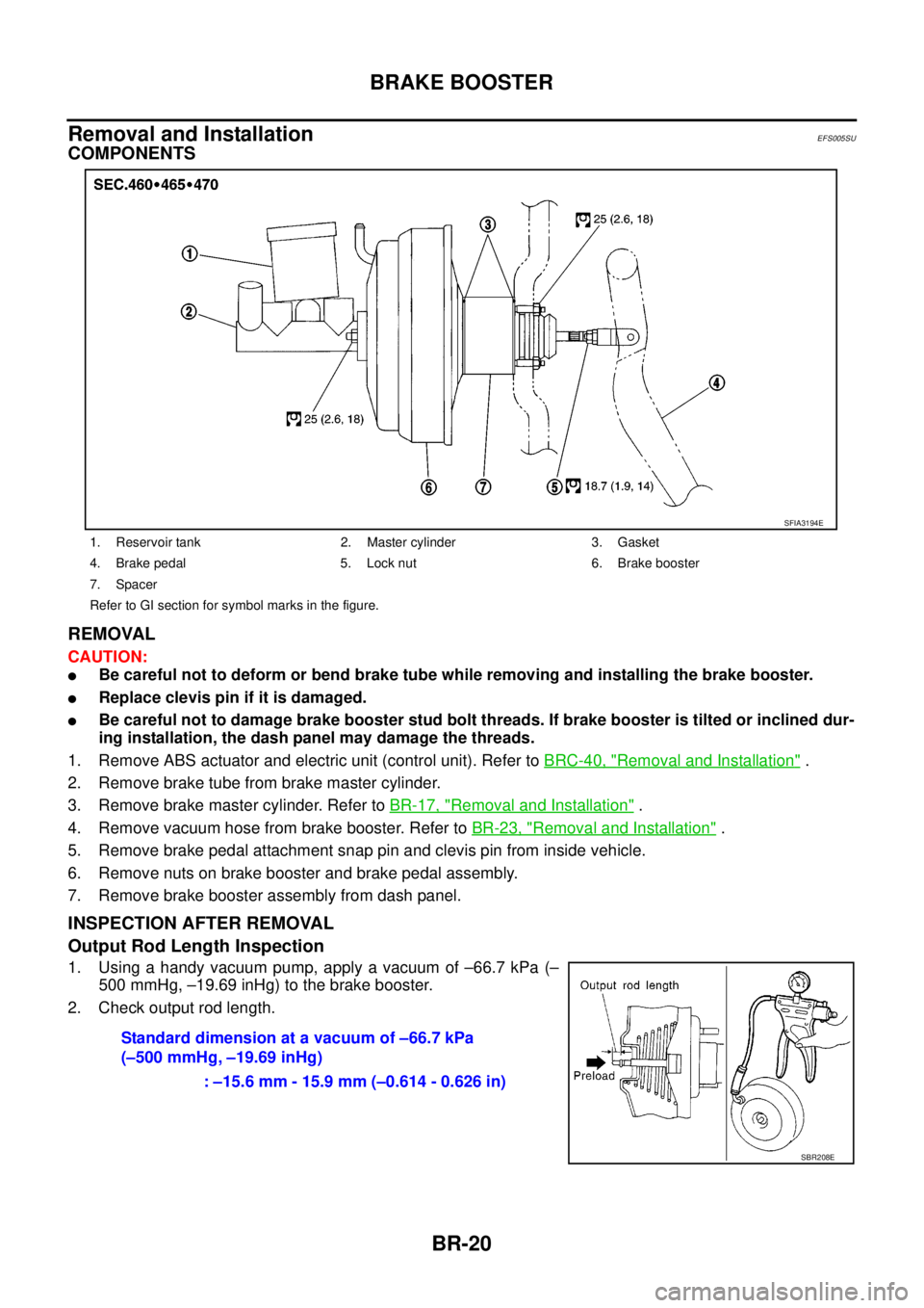
1. Using a handy vacuum pump, apply a vacuum of –66.7 kPa (–
500 mmHg, –19.69 inHg) to the brake booster.
2. Check output rod length.
1. Reservoir tank 2. Master cylinder 3. Gasket
4. Brake pedal 5. Lock nut 6. Brake booster
7. Spacer
Refer to GI section for symbol marks in the figure.
SFIA3194E
Standard dimension at a vacuum of –66.7 kPa
(–500 mmHg, –19.69 inHg)
: –15.6 mm - 15.9 mm (–0.614 - 0.626 in)
SBR208E
Page 807 of 3171

BRAKE BOOSTER
BR-21
C
D
E
G
H
I
J
K
L
MA
B
BR
INSTALLATION
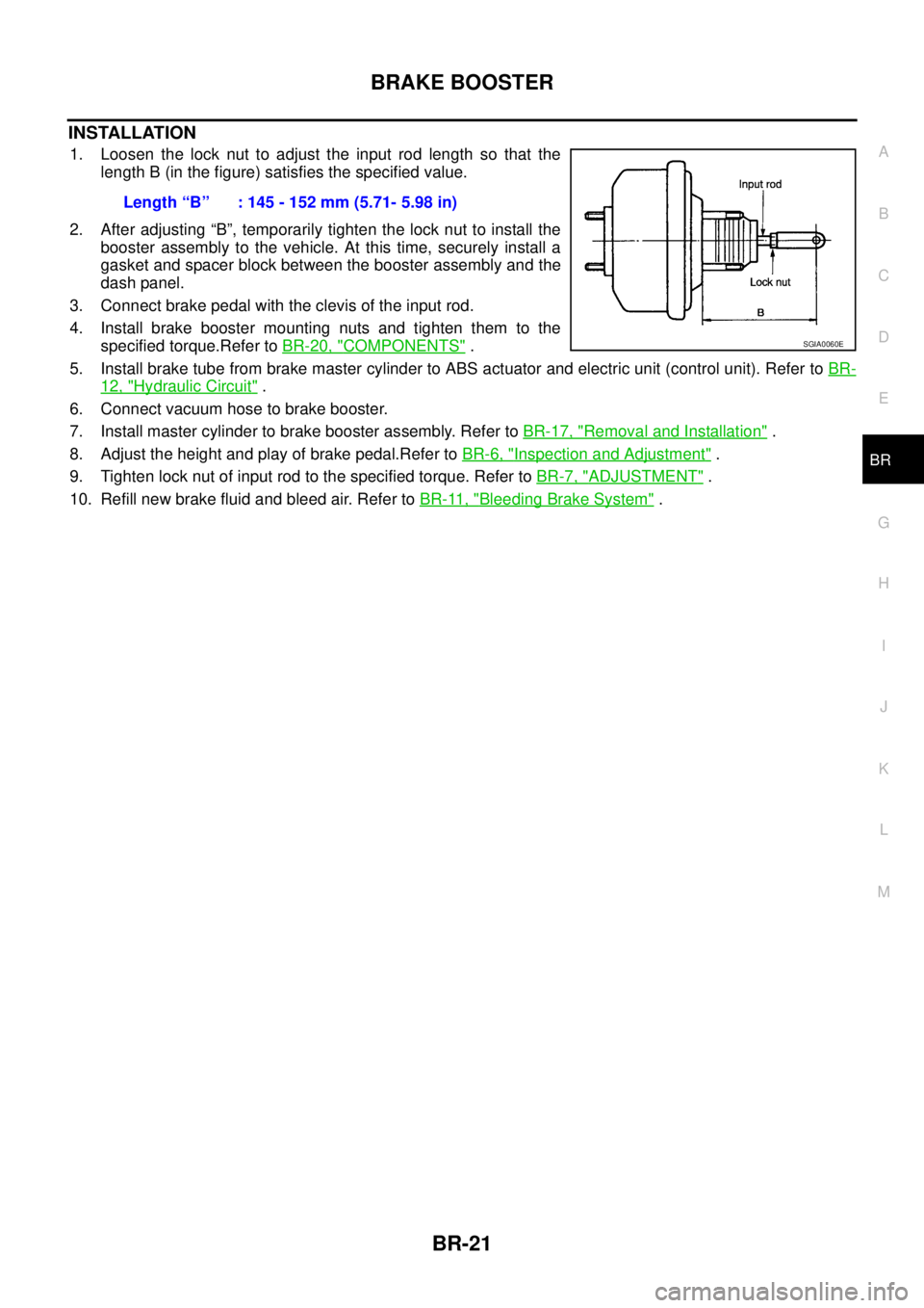
1. Loosen the lock nut to adjust the input rod length so that the
length B (in the figure) satisfies the specified value.
2. After adjusting “B”, temporarily tighten the lock nut to install the
booster assembly to the vehicle. At this time, securely install a
gasket and spacer block between the booster assembly and the
dash panel.
3. Connect brake pedal with the clevis of the input rod.
4. Install brake booster mounting nuts and tighten them to the
specified torque.Refer toBR-20, "
COMPONENTS".
5. Install brake tube from brake master cylinder to ABS actuator and electric unit (control unit). Refer toBR-
12, "Hydraulic Circuit".
6. Connect vacuum hose to brake booster.
7. Install master cylinder to brake booster assembly. Refer toBR-17, "
Removal and Installation".
8. Adjust the height and play of brake pedal.Refer toBR-6, "
Inspection and Adjustment".
9. Tighten lock nut of input rod to the specified torque. Refer toBR-7, "
ADJUSTMENT".
10. Refill new brake fluid and bleed air. Refer toBR-11, "
Bleeding Brake System". Length“B” :145-152mm(5.71-5.98in)
SGIA0060E
Page 813 of 3171

FRONT DISC BRAKE
BR-27
C
D
E
G
H
I
J
K
L
MA
B
BR
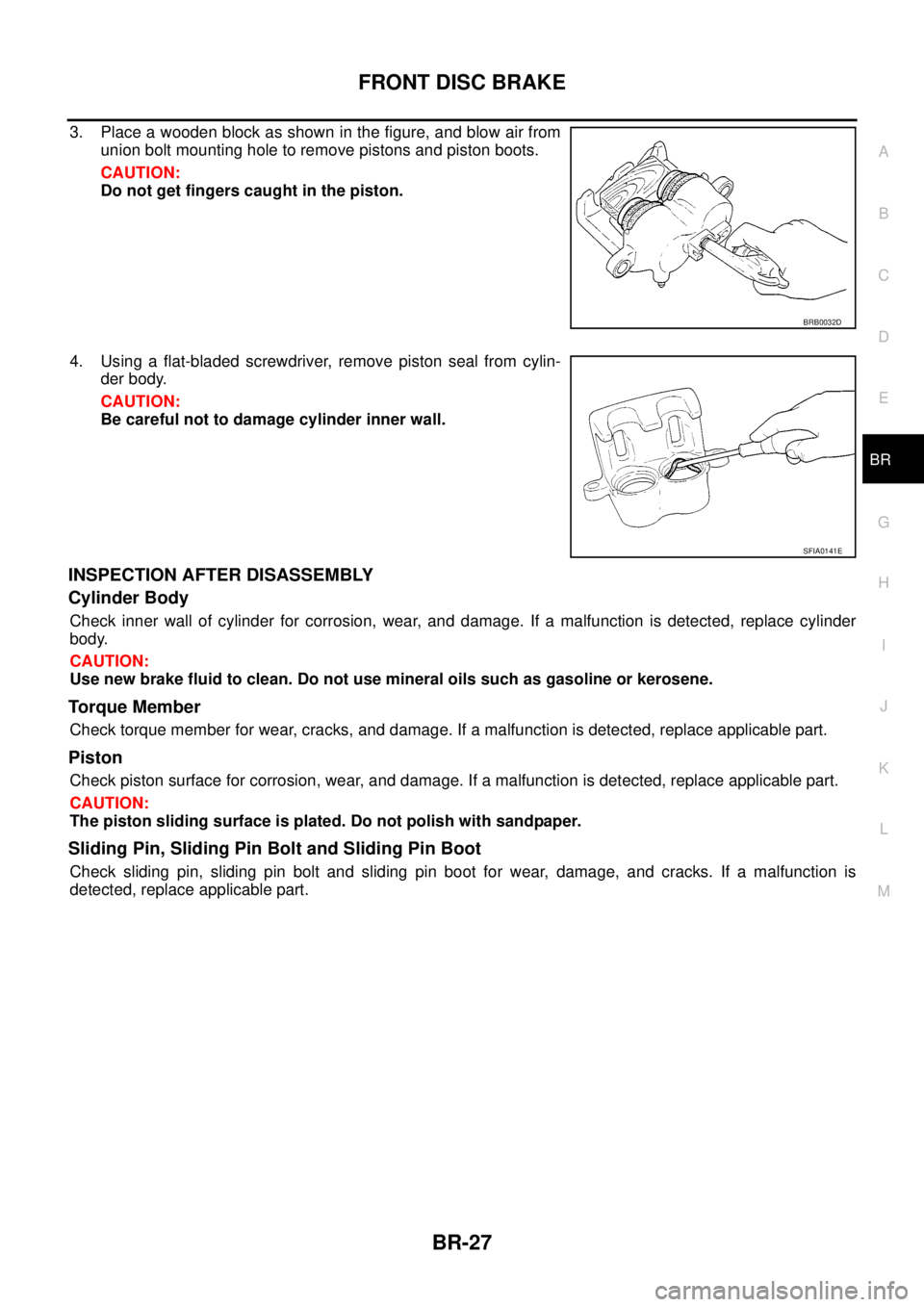
3. Place a wooden block as shown in the figure, and blow air from
union bolt mounting hole to remove pistons and piston boots.
CAUTION:
Do not get fingers caught in the piston.
4. Using a flat-bladed screwdriver, remove piston seal from cylin-
der body.
CAUTION:
Be careful not to damage cylinder inner wall.
INSPECTION AFTER DISASSEMBLY
Cylinder Body
Check inner wall of cylinder for corrosion, wear, and damage. If a malfunction is detected, replace cylinder
body.
CAUTION:
Use new brake fluid to clean. Do not use mineral oils such as gasoline or kerosene.
Torque Member
Check torque member for wear, cracks, and damage. If a malfunction is detected, replace applicable part.
Piston
Check piston surface for corrosion, wear, and damage. If a malfunction is detected, replace applicable part.
CAUTION:
The piston sliding surface is plated. Do not polish with sandpaper.
Sliding Pin, Sliding Pin Bolt and Sliding Pin Boot
Check sliding pin, sliding pin bolt and sliding pin boot for wear, damage, and cracks. If a malfunction is
detected, replace applicable part.
BRB0032D
SFIA0141E