Page 1145 of 3171
DTC P0336 CKP SENSOR
EC-165
C
D
E
F
G
H
I
J
K
L
MA
EC
DTC P0336 CKP SENSORPFP:23731
DescriptionEBS01KGS
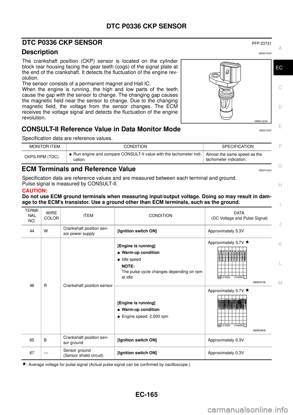
The crankshaft position (CKP) sensor is located on the cylinder
block rear housing facing the gear teeth (cogs) of the signal plate at
the end of the crankshaft. It detects the fluctuation of the engine rev-
olution.
The sensor consists of a permanent magnet and Hall IC.
When the engine is running, the high and low parts of the teeth
cause the gap with the sensor to change. The changing gap causes
the magnetic field near the sensor to change. Due to the changing
magnetic field, the voltage from the sensor changes. The ECM
receives the voltage signal and detects the fluctuation of the engine
revolution.
CONSULT-II Reference Value in Data Monitor ModeEBS01KGT
Specification data are reference values.
ECM Terminals and Reference ValueEBS01KGU
Specification data are reference values and are measured between each terminal and ground.
Pulse signal is measured by CONSULT-II.
CAUTION:
Do not use ECM ground terminals when measuring input/output voltage. Doing so may result in dam-
age to the ECM's transistor. Use a ground other than ECM terminals, such as the ground.
: Average voltage for pulse signal (Actual pulse signal can be confirmed by oscilloscope.)
MBIB1323E
MONITOR ITEM CONDITION SPECIFICATION
CKPS·RPM (TDC)
lRun engine and compare CONSULT-II value with the tachometer indi-
cation.Almost the same speed as the
tachometer indication.
TERMI-
NAL
NO.WIRE
COLORITEM CONDITIONDATA
(DC Voltage and Pulse Signal)
44 WCrankshaft position sen-
sor power supply[Ignition switch ON]Approximately 5.3V
46 R Crankshaft position sensor[Engine is running]
lWarm-up condition
lIdle speed
NOTE:
The pulse cycle changes depending on rpm
at idleApproximately 3.7V
[Engine is running]
lWarm-up condition
lEngine speed: 2,000 rpmApproximately 3.7V
65 BCrankshaft position sen-
sor ground[Ignition switch ON]Approximately 0.3V
67 —Sensor ground
(Sensor shield circuit)[Ignition switch ON]Approximately 0.3V
MBIB0879E
MBIB0880E
Page 1175 of 3171
DTC P0504 ASCD BRAKE SWITCH
EC-195
C
D
E
F
G
H
I
J
K
L
MA
EC
4.DETECT MALFUNCTIONING PART
Check the following.
lFuse block (J/B) connector E103
l10A fuse
lHarness for open or short between stop lamp switch and battery
>> Repair open circuit or short to ground or short to power in harness or connectors.
5.CHECK STOP LAMP SWITCH INPUT SIGNAL CIRCUIT FOR OPEN AND SHORT
1. Disconnect ECM harness connector.
2. Check harness continuity between ECM terminal 100 and stop lamp switch terminal 2.
Refer to Wiring Diagram.
3. Also check harness for short to ground and short to power.
OK or NG
OK >> GO TO 6.
NG >> Repair open circuit or short to ground or short to power in harness or connectors.
6.CHECK STOP LAMP SWITCH
Refer toEC-202, "
Component Inspection".
OK or NG
OK >> GO TO 11.
NG >> Replace stop lamp switch.
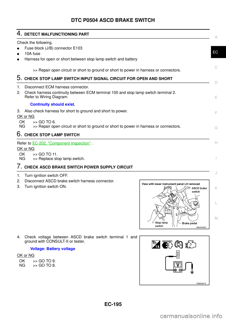
7.CHECK ASCD BRAKE SWITCH POWER SUPPLY CIRCUIT
1. Turn ignition switch OFF.
2. Disconnect ASCD brake switch harness connector.
3. Turn ignition switch ON.
4. Check voltage between ASCD brake switch terminal 1 and
ground with CONSULT-II or tester.
OK or NG
OK >> GO TO 9.
NG >> GO TO 8.Continuity should exist.
BBIA0560E
Voltage: Battery voltage
PBIB0857E
Page 1176 of 3171
EC-196
DTC P0504 ASCD BRAKE SWITCH
8.DETECT MALFUNCTIONING PART
Check the following.
lFuse block (J/B) connector E103
l10A fuse
lHarness for open or short between ASCD brake switch and fuse
>> Repair open circuit or short to ground or short to power in harness or connectors.
9.CHECK ASCD BRAKE SWITCH INPUT SIGNAL CIRCUIT FOR OPEN AND SHORT
1. Disconnect ECM harness connector.
2. Check harness continuity between ECM terminal 101 and ASCD brake switch terminal 2.
Refer to Wiring Diagram.
3. Also check harness for short to ground and short to power.
OK or NG
OK >> GO TO 10.
NG >> Repair open circuit or short to ground or short to power in harness or connectors.
10.CHECK ASCD BRAKE SWITCH
Refer toEC-341, "
Component Inspection"
OK or NG
OK >> GO TO 11.
NG >> Replace ASCD brake switch.
11 .CHECK INTERMITTENT INCIDENT
Refer toEC-70, "
TROUBLE DIAGNOSIS FOR INTERMITTENT INCIDENT".
>>INSPECTION END Continuity should exist.
Page 1179 of 3171
DTC P0504 ASCD BRAKE SWITCH
EC-199
C
D
E
F
G
H
I
J
K
L
MA
EC
4.DETECT MALFUNCTIONING PART
Check the following.
lFuse block (J/B) connector E103
l10A fuse
lHarness for open or short between stop lamp switch and fuse
>> Repair open circuit or short to ground or short to power in harness or connectors.
5.CHECK STOP LAMP SWITCH INPUT SIGNAL CIRCUIT FOR OPEN AND SHORT
1. Disconnect ECM harness connector.
2. Check harness continuity between ECM terminal 100 and stop lamp switch terminal 1.
Refer to Wiring Diagram.
3. Also check harness for short to ground and short to power.
OK or NG
OK >> GO TO 6.
NG >> Repair open circuit or short to ground or short to power in harness or connectors.
6.CHECK STOP LAMP SWITCH
Refer toEC-202, "
Component Inspection".
OK or NG
OK >> GO TO 14.
NG >> Replace stop lamp switch.
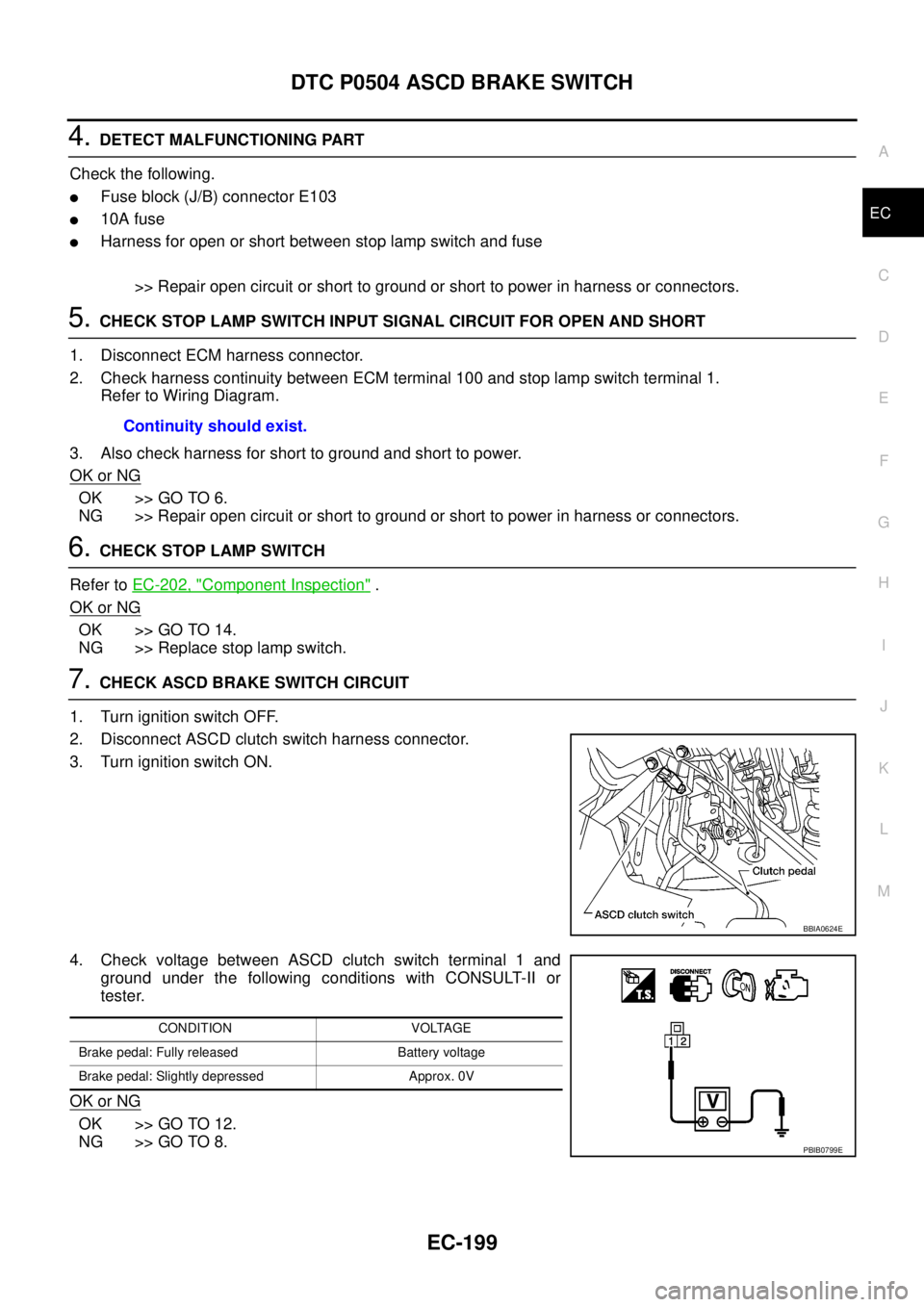
7.CHECK ASCD BRAKE SWITCH CIRCUIT
1. Turn ignition switch OFF.
2. Disconnect ASCD clutch switch harness connector.
3. Turn ignition switch ON.
4. Check voltage between ASCD clutch switch terminal 1 and
ground under the following conditions with CONSULT-II or
tester.
OK or NG
OK >> GO TO 12.
NG >> GO TO 8.Continuity should exist.
BBIA0624E
CONDITION VOLTAGE
Brake pedal: Fully released Battery voltage
Brake pedal: Slightly depressed Approx. 0V
PBIB0799E
Page 1180 of 3171
EC-200
DTC P0504 ASCD BRAKE SWITCH
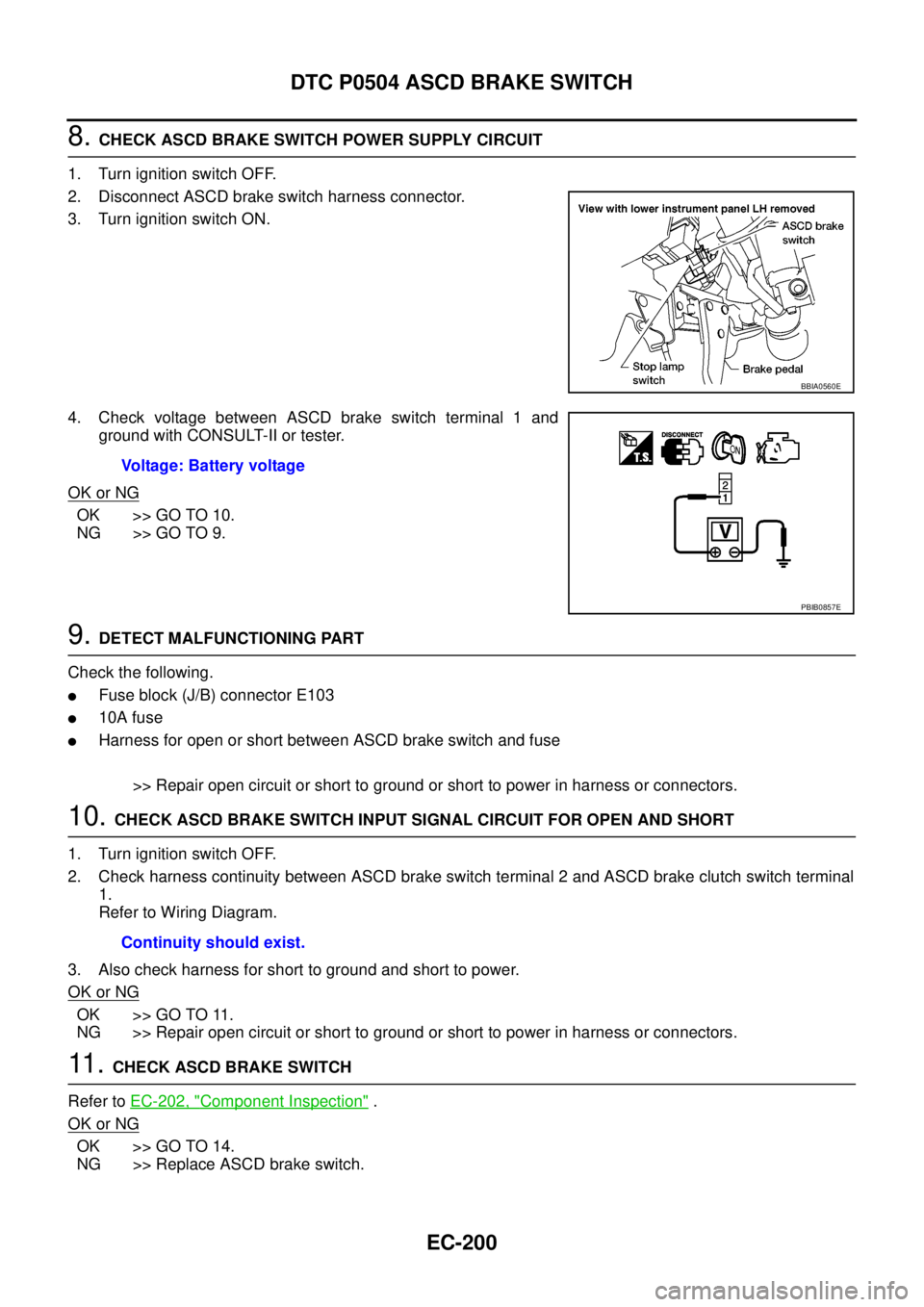
8.CHECK ASCD BRAKE SWITCH POWER SUPPLY CIRCUIT
1. Turn ignition switch OFF.
2. Disconnect ASCD brake switch harness connector.
3. Turn ignition switch ON.
4. Check voltage between ASCD brake switch terminal 1 and
ground with CONSULT-II or tester.
OK or NG
OK >> GO TO 10.
NG >> GO TO 9.
9.DETECT MALFUNCTIONING PART
Check the following.
lFuse block (J/B) connector E103
l10A fuse
lHarness for open or short between ASCD brake switch and fuse
>> Repair open circuit or short to ground or short to power in harness or connectors.
10.CHECK ASCD BRAKE SWITCH INPUT SIGNAL CIRCUIT FOR OPEN AND SHORT
1. Turn ignition switch OFF.
2. Check harness continuity between ASCD brake switch terminal 2 and ASCD brake clutch switch terminal
1.
Refer to Wiring Diagram.
3. Also check harness for short to ground and short to power.
OK or NG
OK >> GO TO 11.
NG >> Repair open circuit or short to ground or short to power in harness or connectors.
11 .CHECK ASCD BRAKE SWITCH
Refer toEC-202, "
Component Inspection".
OK or NG
OK >> GO TO 14.
NG >> Replace ASCD brake switch.
BBIA0560E
Voltage: Battery voltage
PBIB0857E
Continuity should exist.
Page 1302 of 3171
EC-322
HEAT UP SWITCH
3.CHECK HEAT UP SWITCH POWER SUPPLY CIRCUIT
1. Turn heat up switch OFF.
2. Turn ignition switch OFF.
3. Disconnect heat up switch (1) harness connector.
4. Turn ignition switch ON.
5. Check voltage between heat up switch terminal 1 and ground
with CONSULT -II or tester.
OK or NG
OK >> GO TO 5.
NG >> GO TO 4.
4.DETECT MALFUNCTIONING PART
Check the following.
lFuse block (J/B) connector M88
l10A fuse
lHarness for open or short between heat up switch and fuse
>> Repair open circuit or short to ground or short to power in harness or connectors.
5.CHECK HEAT UP SWITCH INPUT SIGNAL CIRCUIT FOR OPEN OR SHORT
1. Turn ignition switch OFF.
2. Disconnect ECM harness connector.
3. Check harness continuity between ECM terminal 13 and heat up switch terminal 2. Refer to Wiring Dia-
gram.
4. Also check harness for short to ground and short to power.
OK or NG
OK >> GO TO 8.
NG >> GO TO 6.
MBIB1221E
Voltage: Battery voltage
MBIB1245E
Continuity should exist.
Page 1314 of 3171
EC-334
BRAKE SWITCH
4.DETECT MALFUNCTIONING PART
Check the following.
lFuse block (J/B) connector E103
l10A fuse
lHarness for open or short between stop lamp switch and battery
>> Repair open circuit or short to ground or short to power in harness or connectors.
5.CHECK STOP LAMP SWITCH INPUT SIGNAL CIRCUIT FOR OPEN AND SHORT
1. Disconnect ECM harness connector.
2. Check harness continuity between ECM terminal 100 and stop lamp switch terminal 2.
Refer to Wiring Diagram.
3. Also check harness for short to ground and short to power.
OK or NG
OK >> GO TO 6.
NG >> Repair open circuit or short to ground or short to power in harness or connectors.
6.CHECK STOP LAMP SWITCH
Refer toEC-341, "
Component Inspection".
OK or NG
OK >> GO TO 11.
NG >> Replace stop lamp switch.
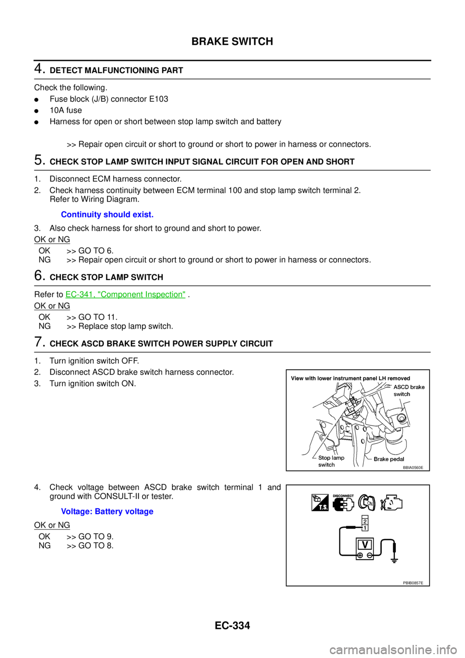
7.CHECK ASCD BRAKE SWITCH POWER SUPPLY CIRCUIT
1. Turn ignition switch OFF.
2. Disconnect ASCD brake switch harness connector.
3. Turn ignition switch ON.
4. Check voltage between ASCD brake switch terminal 1 and
ground with CONSULT-II or tester.
OK or NG
OK >> GO TO 9.
NG >> GO TO 8.Continuity should exist.
BBIA0560E
Voltage: Battery voltage
PBIB0857E
Page 1315 of 3171
BRAKE SWITCH
EC-335
C
D
E
F
G
H
I
J
K
L
MA
EC
8.DETECT MALFUNCTIONING PART
Check the following.
lFuse block (J/B) connector E103
l10A fuse
lHarness for open or short between ASCD brake switch and fuse
>> Repair open circuit or short to ground or short to power in harness or connectors.
9.CHECK ASCD BRAKE SWITCH INPUT SIGNAL CIRCUIT FOR OPEN AND SHORT
1. Disconnect ECM harness connector.
2. Check harness continuity between ECM terminal 101 and ASCD brake lamp switch terminal 2.
Refer to Wiring Diagram.
3. Also check harness for short to ground and short to power.
OK or NG
OK >> GO TO 10.
NG >> Repair open circuit or short to ground or short to power in harness or connectors.
10.CHECK ASCD BRAKE SWITCH
Refer toEC-341, "
Component Inspection"
OK or NG
OK >> GO TO 11.
NG >> Replace ASCD brake switch.
11 .CHECK INTERMITTENT INCIDENT
Refer toEC-70, "
TROUBLE DIAGNOSIS FOR INTERMITTENT INCIDENT".
>>INSPECTION END Continuity should exist.