2005 NISSAN NAVARA ignition
[x] Cancel search: ignitionPage 768 of 3171
BL-184
NATS(NISSAN ANTI-THEFT SYSTEM)
Diagnostic Procedure 4
EIS00DB4
Self-diagnostic results:
“ID DISCORD, IMM-ECM” displayed on CONSULT-II screen
1.CONFIRM SELF-DIAGNOSTIC RESULTS
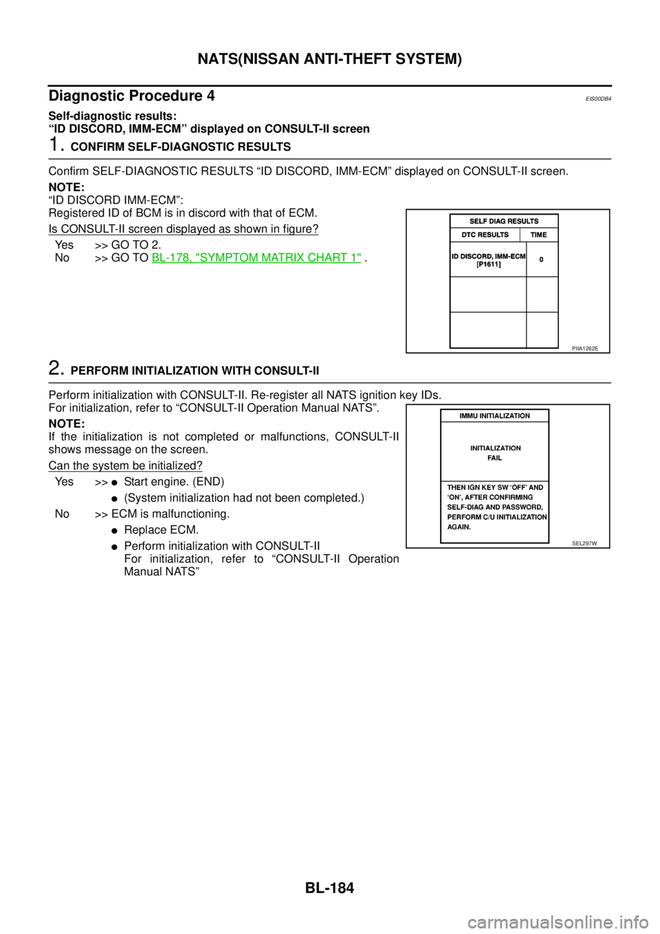
Confirm SELF-DIAGNOSTIC RESULTS “ID DISCORD, IMM-ECM” displayed on CONSULT-II screen.
NOTE:
“ID DISCORD IMM-ECM”:
Registered ID of BCM is in discord with that of ECM.
Is CONSULT-II screen displayed as shown in figure?
Yes >>GOTO2.
No >> GO TOBL-178, "
SYMPTOM MATRIX CHART 1".
2.PERFORM INITIALIZATION WITH CONSULT-II
Perform initialization with CONSULT-II. Re-register all NATS ignition key IDs.
For initialization, refer to “CONSULT-II Operation Manual NATS”.
NOTE:
If the initialization is not completed or malfunctions, CONSULT-II
shows message on the screen.
Can the system be initialized?
Ye s > >lStart engine. (END)
l(System initialization had not been completed.)
No >> ECM is malfunctioning.
lReplace ECM.
lPerform initialization with CONSULT-II
For initialization, refer to “CONSULT-II Operation
Manual NATS”
PIIA1262E
SEL297W
Page 769 of 3171
NATS(NISSAN ANTI-THEFT SYSTEM)
BL-185
C
D
E
F
G
H
J
K
L
MA
B
BL
Diagnostic Procedure 5EIS00DB5
“SECURITY INDICATOR LAMP DOES NOT LIGHT UP”
1.SECURITY INDICATOR LAMP ACTIVE TEST
With CONSULT-II
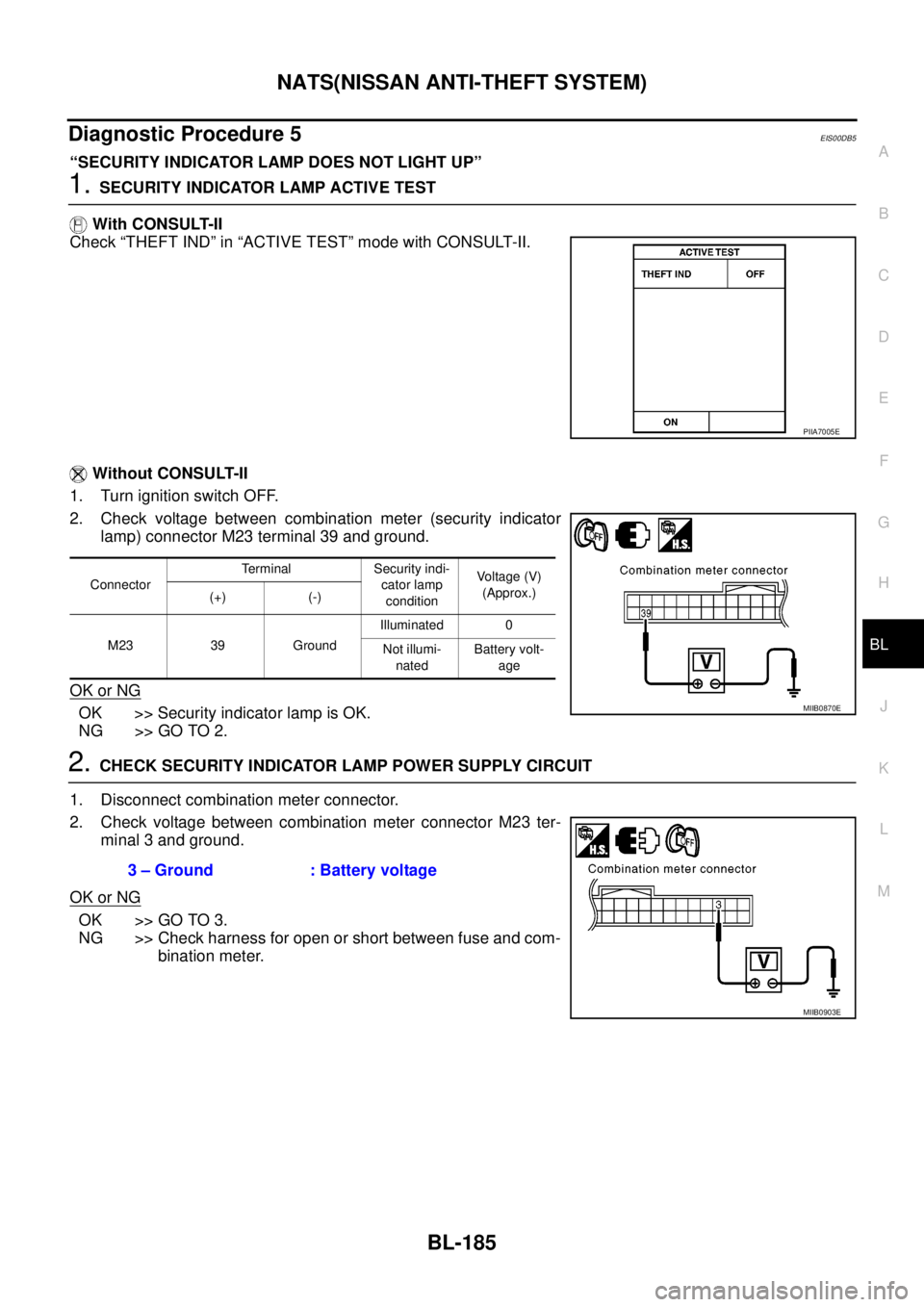
Check “THEFT IND” in “ACTIVE TEST” mode with CONSULT-II.
Without CONSULT-II
1. Turn ignition switch OFF.
2. Check voltage between combination meter (security indicator
lamp) connector M23 terminal 39 and ground.
OK or NG
OK >> Security indicator lamp is OK.
NG >> GO TO 2.
2.CHECK SECURITY INDICATOR LAMP POWER SUPPLY CIRCUIT
1. Disconnect combination meter connector.
2. Check voltage between combination meter connector M23 ter-
minal 3 and ground.
OK or NG
OK >> GO TO 3.
NG >> Check harness for open or short between fuse and com-
bination meter.
PIIA7005E
ConnectorTerminal Security indi-
cator lamp
conditionVoltage (V)
(Approx.)
(+) (-)
M23 39 GroundIlluminated 0
Not illumi-
natedBattery volt-
age
MIIB0870E
3 – Ground : Battery voltage
MIIB0903E
Page 770 of 3171
BL-186
NATS(NISSAN ANTI-THEFT SYSTEM)
3.CHECK SECURITY INDICATOR OPERATION
1. Turn ignition switch OFF.
2. Disconnect BCM and combination meter connector.
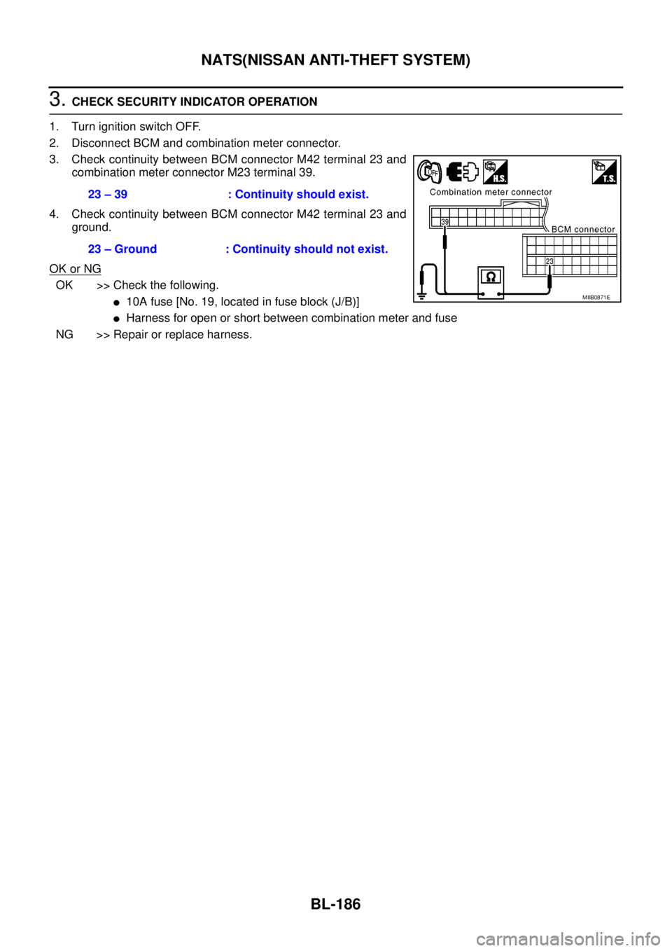
3. Check continuity between BCM connector M42 terminal 23 and
combination meter connector M23 terminal 39.
4. Check continuity between BCM connector M42 terminal 23 and
ground.
OK or NG
OK >> Check the following.
l10A fuse [No. 19, located in fuse block (J/B)]
lHarness for open or short between combination meter and fuse
NG >> Repair or replace harness.23 – 39 : Continuity should exist.
23 – Ground : Continuity should not exist.
MIIB0871E
Page 771 of 3171
NATS(NISSAN ANTI-THEFT SYSTEM)
BL-187
C
D
E
F
G
H
J
K
L
MA
B
BL
Diagnostic Procedure 6EIS00DB6
Self-diagnostic results:
“LOCK MODE” displayed on CONSULT-II screen
1.CONFIRM SELF-DIAGNOSTIC RESULTS
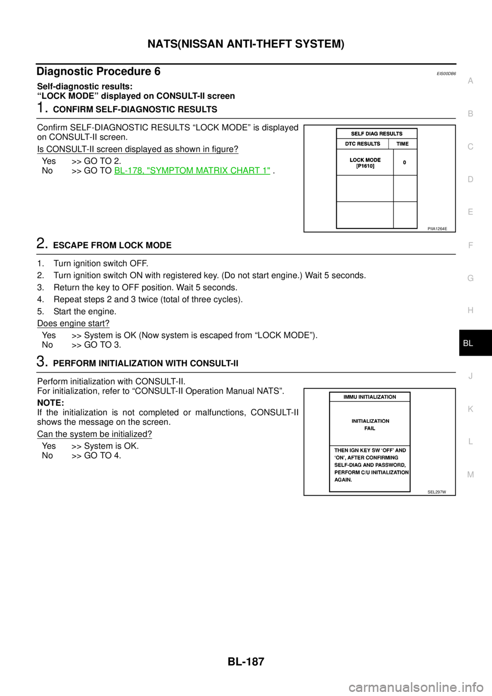
Confirm SELF-DIAGNOSTIC RESULTS “LOCK MODE” is displayed
on CONSULT-II screen.
Is CONSULT-II screen displayed as shown in figure?
Ye s > > G O T O 2 .
No >> GO TOBL-178, "
SYMPTOM MATRIX CHART 1".
2.ESCAPE FROM LOCK MODE
1. Turn ignition switch OFF.
2. Turn ignition switch ON with registered key. (Do not start engine.) Wait 5 seconds.
3. Return the key to OFF position. Wait 5 seconds.
4. Repeat steps 2 and 3 twice (total of three cycles).
5. Start the engine.
Does engine start?
Yes >>SystemisOK(Nowsystemisescapedfrom“LOCKMODE”).
No >> GO TO 3.
3.PERFORM INITIALIZATION WITH CONSULT-II
Perform initialization with CONSULT-II.
For initialization, refer to “CONSULT-II Operation Manual NATS”.
NOTE:
If the initialization is not completed or malfunctions, CONSULT-II
shows the message on the screen.
Can the system be initialized?
Yes >>SystemisOK.
No >> GO TO 4.
PIIA1264E
SEL297W
Page 772 of 3171
BL-188
NATS(NISSAN ANTI-THEFT SYSTEM)
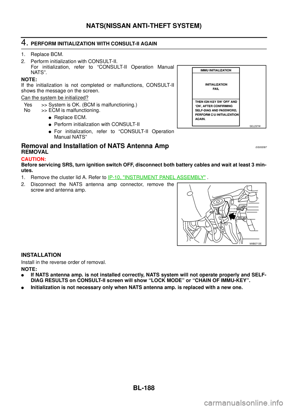
4.PERFORM INITIALIZATION WITH CONSULT-II AGAIN
1. Replace BCM.
2. Perform initialization with CONSULT-II.
For initialization, refer to “CONSULT-II Operation Manual
NATS”.
NOTE:
If the initialization is not completed or malfunctions, CONSULT-II
shows the message on the screen.
Can the system be initialized?
Yes >>SystemisOK.(BCMismalfunctioning.)
No >> ECM is malfunctioning.
lReplace ECM.
lPerform initialization with CONSULT-II
lFor initialization, refer to “CONSULT-II Operation
Manual NATS”
Removal and Installation of NATS Antenna AmpEIS00DB7
REMOVAL
CAUTION:
Before servicing SRS, turn ignition switch OFF, disconnect both battery cables and wait at least 3 min-
utes.
1. Remove the cluster lid A. Refer toIP-10, "
INSTRUMENT PANEL ASSEMBLY".
2. Disconnect the NATS antenna amp connector, remove the
screw and antenna amp.
INSTALLATION
Install in the reverse order of removal.
NOTE:
lIf NATS antenna amp. is not installed correctly, NATS system will not operate properly and SELF-
DIAG RESULTS on CONSULT-II screen will show “LOCK MODE” or “CHAIN OF IMMU-KEY”.
lInitialization is not necessary only when NATS antenna amp. is replaced with a new one.
SEL297W
MIIB0713E
Page 789 of 3171
PRECAUTIONS
BR-3
C
D
E
G
H
I
J
K
L
MA
B
BR
PRECAUTIONSPFP:00001
Precautions for Supplemental Restraint System (SRS) “AIR BAG” and “SEAT
BELT PRE-TENSIONER”
EFS006DL
The Supplemental Restraint System such as “AIR BAG” and “SEAT BELT PRE-TENSIONER”, used along
with a front seat belt, helps to reduce the risk or severity of injury to the driver and front passenger for certain
types of collision. Information necessary to service the system safely is included in the SRS and SB section of
this Service Manual.
WARNING:
lTo avoid rendering the SRS inoperative, which could increase the risk of personal injury or death
in the event of a collision which would result in air bag inflation, all maintenance must be per-
formed by an authorized NISSAN/INFINITI dealer.
lImproper maintenance, including incorrect removal and installation of the SRS, can lead to per-
sonal injury caused by unintentional activation of the system. For removal of Spiral Cable and Air
Bag Module, see the SRS section.
lDo not use electrical test equipment on any circuit related to the SRS unless instructed to in this
Service Manual. SRS wiring harnesses can be identified by yellow and/or orange harnesses or
harness connectors.
Precautions for Brake SystemEFS005SD
lClean dust on front brake and rear brake with a vacuum dust collector. Do not blow with compressed air.
lRecommended fluid is brake fluid “DOT 3” or “DOT 4”.
lNever reuse drained brake fluid.
lBe careful not to splash brake fluid on painted areas; it may cause paint damage. If brake fluid is splashed
on painted areas, wash it away with water immediately.
lTo clean or wash all parts of master cylinder, disc brake caliper, wheel cylinder, use new brake fluid.
lNever use mineral oils such as gasoline or kerosene. They will ruin rubber parts of the hydraulic system.
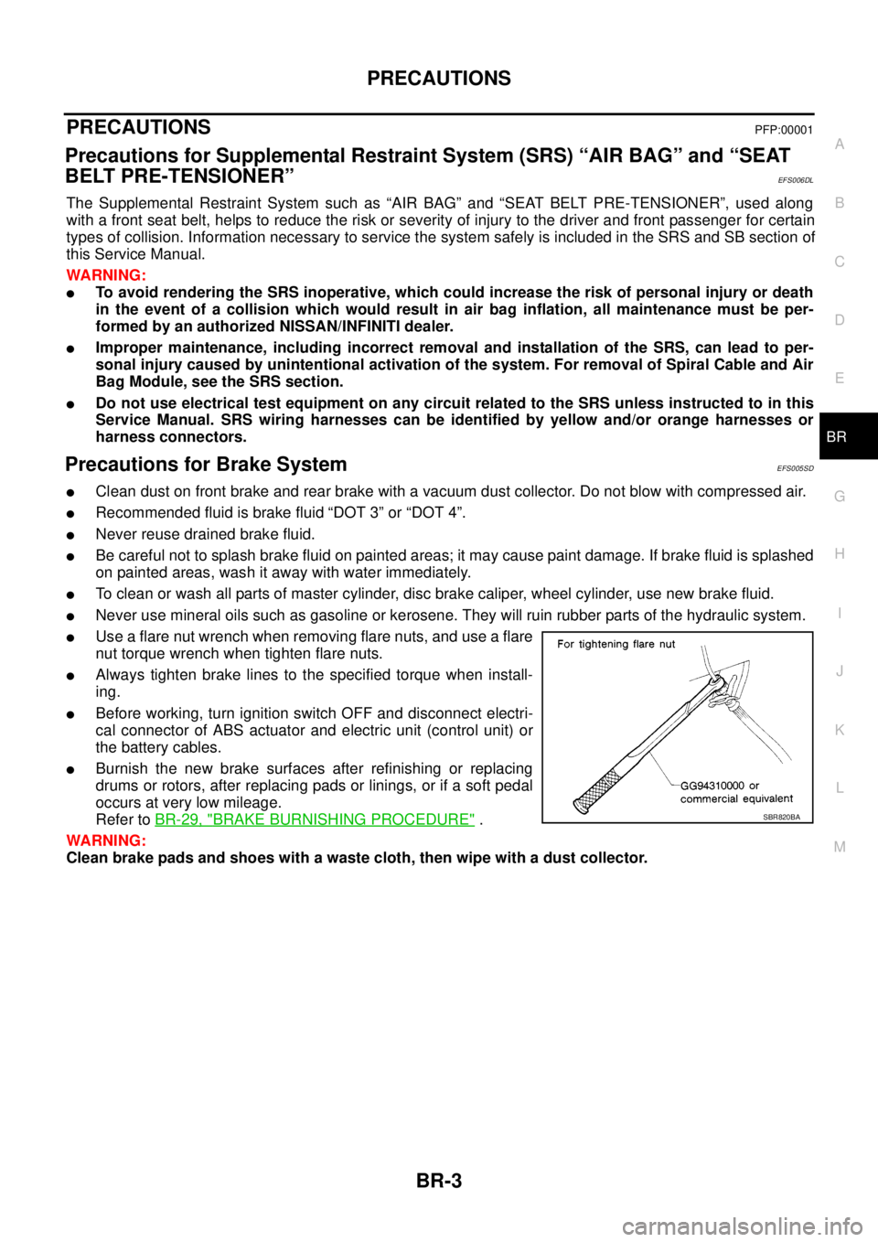
lUse a flare nut wrench when removing flare nuts, and use a flare
nut torque wrench when tighten flare nuts.
lAlways tighten brake lines to the specified torque when install-
ing.
lBefore working, turn ignition switch OFF and disconnect electri-
cal connector of ABS actuator and electric unit (control unit) or
the battery cables.
lBurnish the new brake surfaces after refinishing or replacing
drums or rotors, after replacing pads or linings, or if a soft pedal
occurs at very low mileage.
Refer toBR-29, "
BRAKE BURNISHING PROCEDURE".
WARNING:
Clean brake pads and shoes with a waste cloth, then wipe with a dust collector.SBR820BA
Page 825 of 3171
![NISSAN NAVARA 2005 Repair Workshop Manual PRECAUTIONS
BRC-3
[ABS]
C
D
E
G
H
I
J
K
L
MA
B
BRC
[ABS]PRECAUTIONSPFP:00001
Precautions for Supplemental Restraint System (SRS) “AIR BAG” and “SEAT
BELT PRE-TENSIONER”
EFS006DM
The Supplement NISSAN NAVARA 2005 Repair Workshop Manual PRECAUTIONS
BRC-3
[ABS]
C
D
E
G
H
I
J
K
L
MA
B
BRC
[ABS]PRECAUTIONSPFP:00001
Precautions for Supplemental Restraint System (SRS) “AIR BAG” and “SEAT
BELT PRE-TENSIONER”
EFS006DM
The Supplement](/manual-img/5/57362/w960_57362-824.png)
PRECAUTIONS
BRC-3
[ABS]
C
D
E
G
H
I
J
K
L
MA
B
BRC
[ABS]PRECAUTIONSPFP:00001
Precautions for Supplemental Restraint System (SRS) “AIR BAG” and “SEAT
BELT PRE-TENSIONER”
EFS006DM
The Supplemental Restraint System such as “AIR BAG” and “SEAT BELT PRE-TENSIONER”, used along
with a front seat belt, helps to reduce the risk or severity of injury to the driver and front passenger for certain
types of collision. Information necessary to service the system safely is included in the SRS and SB section of
this Service Manual.
WARNING:
lTo avoid rendering the SRS inoperative, which could increase the risk of personal injury or death
in the event of a collision which would result in air bag inflation, all maintenance must be per-
formed by an authorized NISSAN/INFINITI dealer.
lImproper maintenance, including incorrect removal and installation of the SRS, can lead to per-
sonal injury caused by unintentional activation of the system. For removal of Spiral Cable and Air
Bag Module, see the SRS section.
lDo not use electrical test equipment on any circuit related to the SRS unless instructed to in this
Service Manual. SRS wiring harnesses can be identified by yellow and/or orange harnesses or
harness connectors.
Precautions for Brake SystemEFS005TG
lRecommended fluid is brake fluid “DOT 3” or “DOT 4”.
lNever reuse drained brake fluid.
lBe careful not to splash brake fluid on painted areas.If brake fluid is splashed, wipe it off and flush area
with water immediately.
lNever use mineral oils such as gasoline or kerosene. They will ruin rubber parts of the hydraulic system.
lUse flare nut wrench when removing flare nuts, and use a flare
nut torque wrench when tighten flare nuts.
lBrake system is an important safety part.If a brake fluid leak is
detected, always disassemble the affected part.If a malfunction
is detected, replace part with new one.
lBefore working, turn ignition switch OFF and disconnect con-
nector of ABS actuator and electric unit (control unit) or the bat-
tery cables.
lWhen installing brake tube and hose, be sure to torque.
WARNING:
Clean brake pads and shoes with a waster cloth, then wipe with
a dust collector.
Precautions for Brake ControlEFS005TH
lJust after starting vehicle after ignition switch ON, brake pedal may vibrate or motor operating noise may
be heard from engine room. This is a normal status of operation check.
lStopping distance may be longer than that of vehicles without ABS when vehicle drives on rough, gravel,
or snow-covered (fresh, deep snow) roads.
lWhen an error is indicated by ABS or another warning lamp, collect all necessary information from cus-
tomer (what symptoms are present under what conditions) and check for simple causes before starting
diagnostic servicing. Besides electrical system inspection, check brake booster operation, brake fluid
level, and fluid leaks.
lIf tyre size and type are used in an improper combination, or brake pads are not Genuine NISSAN parts,
stopping distance or steering stability may deteriorate.
lIf there is a radio, antenna, or antenna lead-in wire (including wiring) near control module, ABS function
may have a malfunction or error.
lIf aftermarket parts (car stereo, CD player, etc.) have been installed, check for incidents such as harness
pinches, open circuits, and improper wiring.
SBR820BA
Page 827 of 3171
![NISSAN NAVARA 2005 Repair Workshop Manual SYSTEM DESCRIPTION
BRC-5
[ABS]
C
D
E
G
H
I
J
K
L
MA
B
BRC
SYSTEM DESCRIPTIONPFP:00000
System DiagramEFS005TJ
FunctionsEFS005TK
ABS
lThe Anti-Lock Brake System is a function that detects wheel revoluti NISSAN NAVARA 2005 Repair Workshop Manual SYSTEM DESCRIPTION
BRC-5
[ABS]
C
D
E
G
H
I
J
K
L
MA
B
BRC
SYSTEM DESCRIPTIONPFP:00000
System DiagramEFS005TJ
FunctionsEFS005TK
ABS
lThe Anti-Lock Brake System is a function that detects wheel revoluti](/manual-img/5/57362/w960_57362-826.png)
SYSTEM DESCRIPTION
BRC-5
[ABS]
C
D
E
G
H
I
J
K
L
MA
B
BRC
SYSTEM DESCRIPTIONPFP:00000
System DiagramEFS005TJ
FunctionsEFS005TK
ABS
lThe Anti-Lock Brake System is a function that detects wheel revolution while braking, and it improves
handling stability during sudden braking by electrically preventing 4 wheels lock. Maneuverability is also
improved for avoiding obstacles.
lElectrical system diagnosis by CONSULT-II is available.
EBD
lElectronic Brake Distributor is a function that detects subtle slippages between the front and rear tyre dur-
ing braking, and it improves handling stability by electrically controlling the brake fluid pressure which
results in reduced rear tyre slippage.
lElectrical system diagnosis by CONSULT-II is available.
Operation That Is Not “System Error”EFS005TL
ABS
lWhen starting engine or just after starting vehicle, brake pedal may vibrate or the motor operating noise
may be heard from engine room. This is a normal states of the operation check.
lDuring ABS operation, brake pedal lightly vibrates and a mechanical noise may be heard. This is normal.
lStopping distance may be longer than that of vehicles without ABS when vehicle drives on rough, gravel,
or snow-covered (fresh, deep snow) roads.
Fail-Safe FunctionEFS005TM
ABS, EBD SYSTEM
In case of electrical malfunction with ABS, ABS warning lamp will turn on. In case of electrical incidents with
EBD, brake warning lamp and ABS warning lamp will turn on. Simultaneously, ABS become one of following
conditions of Fail-Safe function.
1. For ABS malfunction, only EBD is activated and condition of vehicle is same condition of vehicles without
ABS system.
NOTE:
ABS self-diagnosis sound may be heard.That is a normal condition because a self-diagnosis for “Ignition
switch ON” and “The first starting” are being performed.
2. For EBD malfunction, EBD and ABS become inoperative, and condition of vehicle is same as condition of
vehicles without ABS, EBD system.
SFIA3001E