Page 746 of 3171
BL-162
THEFT WARNING SYSTEM
Diagnostic Procedure 1
EIS00DC8
CHECK DOOR SWITCH (DOUBLE CAB)
1.CHECK DOOR SWITCH INPUT SIGNAL
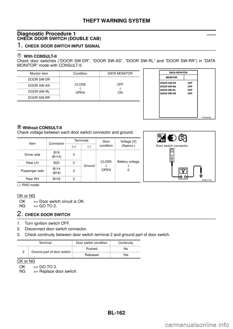
With CONSULT-II
Check door switches (“DOOR SW-DR”, “DOOR SW-AS”, “DOOR SW-RL” and “DOOR SW-RR”) in “DATA
MONITOR” mode with CONSULT-II.
Without CONSULT-II
Check voltage between each door switch connector and ground.
( ): RHD model
OK or NG
OK >> Door switch circuit is OK.
NG >> GO TO 2.
2.CHECK DOOR SWITCH
1. Turn ignition switch OFF.
2. Disconnect door switch connector.
3. Check continuity between door switch terminal 2 and ground part of door switch.
OK or NG
OK >> GO TO 3.
NG >> Replace door switch.
Monitor item Condition DATA MONITOR
DOOR SW-DR
CLOSE
¯
OPENOFF
¯
ON DOOR SW-AS
DOOR SW-RL
DOOR SW-RR
PIIA6469E
Item ConnectorTerminals
Door
conditionVoltage [V]
(Approx.)
(+) (-)
Driver sideB19
(B114)2
GroundCLOSE
¯
OPENBattery voltage
¯
0 Rear LH B23 2
Passenger sideB114
(B19)2
Rear RH B116 2
MIIB0773E
Terminal Door switch condition Continuity
2 Ground part of door switchPushed No
Released Yes
Page 749 of 3171
THEFT WARNING SYSTEM
BL-165
C
D
E
F
G
H
J
K
L
MA
B
BL
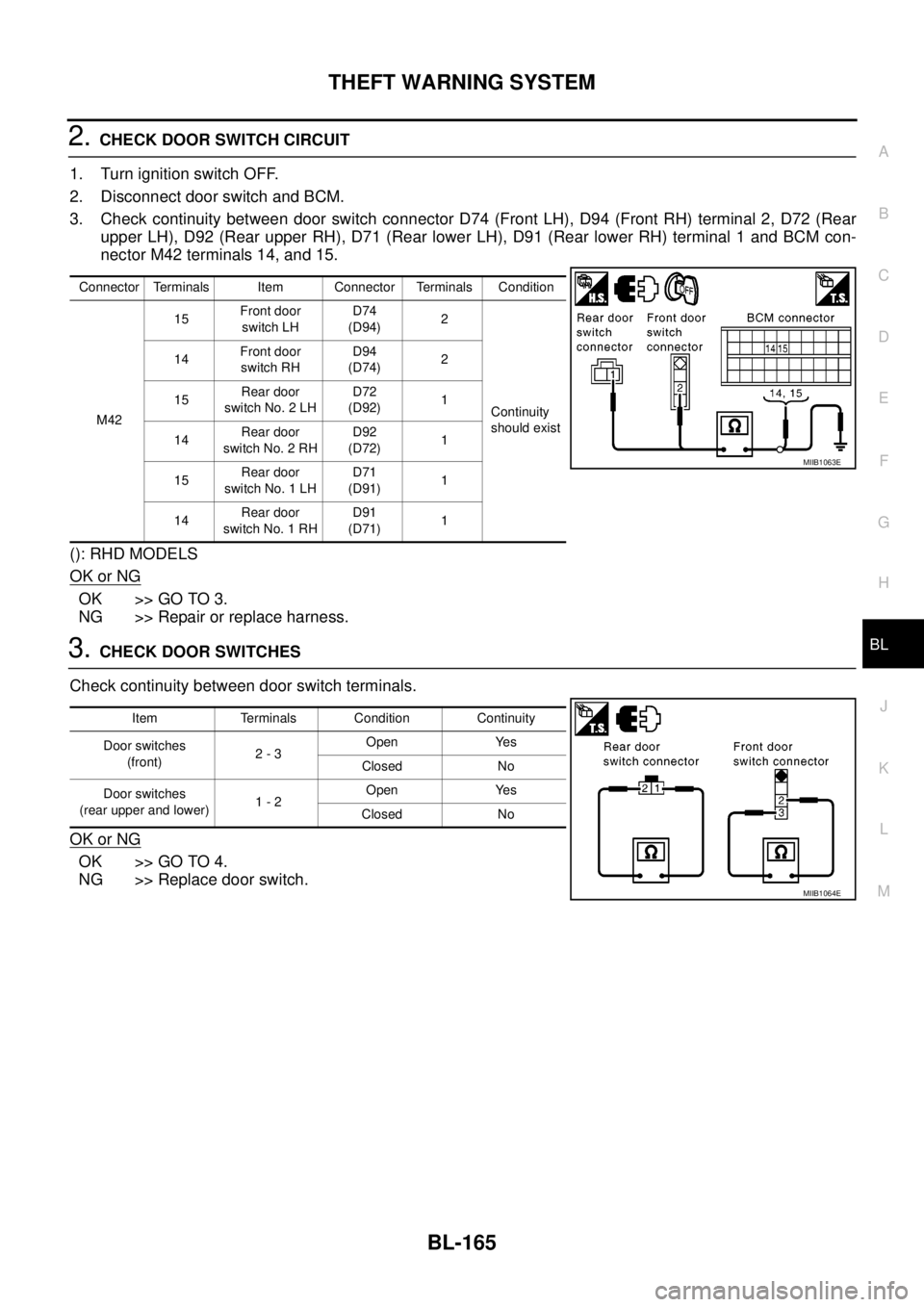
2.CHECK DOOR SWITCH CIRCUIT
1. Turn ignition switch OFF.
2. Disconnect door switch and BCM.
3. Check continuity between door switch connector D74 (Front LH), D94 (Front RH) terminal 2, D72 (Rear
upper LH), D92 (Rear upper RH), D71 (Rear lower LH), D91 (Rear lower RH) terminal 1 and BCM con-
nector M42 terminals 14, and 15.
(): RHD MODELS
OK or NG
OK >> GO TO 3.
NG >> Repair or replace harness.
3.CHECK DOOR SWITCHES
Check continuity between door switch terminals.
OK or NG
OK >> GO TO 4.
NG >> Replace door switch.
Connector Terminals Item Connector Terminals Condition
M4215Front door
switch LHD74
(D94)2
Continuity
should exist 14Front door
switch RHD94
(D74)2
15Rear door
switch No. 2 LHD72
(D92)1
14Rear door
switch No. 2 RHD92
(D72)1
15Rear door
switch No. 1 LHD71
(D91)1
14Rear door
switch No. 1 RHD91
(D71)1
MIIB1063E
Item Terminals Condition Continuity
Door switches
(front)2-3Open Yes
Closed No
Door switches
(rear upper and lower)1-2Open Yes
Closed No
MIIB1064E
Page 751 of 3171
THEFT WARNING SYSTEM
BL-167
C
D
E
F
G
H
J
K
L
MA
B
BL
2.CHECK HOOD SWITCH
1. Turn ignition switch OFF.
2. Disconnect hood switch connector.
3. Check continuity between hood switch terminal 1 and 2.
OK or NG
OK >> GO TO 3.
NG >> Replace hood switch.
3.CHECK HOOD SWITCH CIRCUIT
1. Disconnect IPDM E/R connector.
2. Check continuity between hood switch connector E51 terminals
1 and IPDM E/R connector E17 terminals 41.
3. Check continuity between hood switch connector E51 terminal 1
and ground.
OK or NG
OK >> GO TO 4.
NG >> Repair or replace harness.
4.CHECK GROUND CIRCUIT
Check continuity between hood switch connector E51 terminal 2 and
ground.
OK or NG
OK >> GO TO 5.
NG >> Repair or replace harness.
Terminals Hood switch condition Continuity
12Pressed No
Released Yes
PIIA2498E
1 – 41 : Continuity should exist.
1 – Ground : Continuity should not exist.
MIIB0869E
2 – Ground : Continuity should exist.
PIIA8127E
Page 752 of 3171
BL-168
THEFT WARNING SYSTEM
5.CHECK IPDM E/R OUTPUT SIGNAL
1. Connect IPDM E/R connector.
2. Check voltage between IPDM E/R terminal 41 and ground.
OK or NG
OK >> Check harness condition.
NG >> Replace IPDM E/R.
Diagnostic Procedure 2EIS00DC9
SECURITY INDICATOR LAMP CHECK
1.SECURITY INDICATOR LAMP ACTIVE TEST
With CONSULT-II
Check "THEFT IND” in "ACTIVE TEST" mode with CONSULT-II.
Without CONSULT-II
1. Turn ignition switch OFF.
2. Check voltage between combination meter (security indicator
lamp) connector M23 terminal 39 and ground.
OK or NG
OK >> Security indicator lamp is OK.
NG >> GO TO 2.41 – Ground : Battery voltage
MIIB0868E
PIIA7005E
ConnectorTerminal Security indi-
cator lamp
conditionVo l ta g e (V )
(Approx.)
(+) (-)
M23 39 GroundIlluminated 0
Not illumi-
natedBattery volt-
age
MIIB0870E
Page 753 of 3171
THEFT WARNING SYSTEM
BL-169
C
D
E
F
G
H
J
K
L
MA
B
BL
2.CHECK HARNESS CONTINUITY
1. Turn ignition switch OFF.
2. Disconnect BCM and combination meter connector.
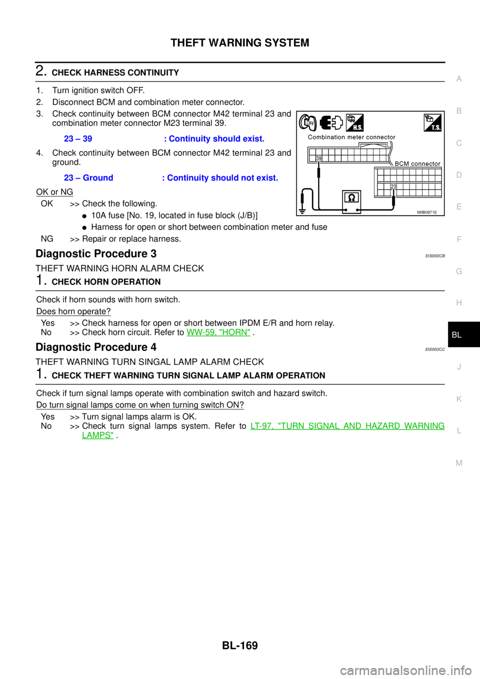
3. Check continuity between BCM connector M42 terminal 23 and
combination meter connector M23 terminal 39.
4. Check continuity between BCM connector M42 terminal 23 and
ground.
OK or NG
OK >> Check the following.
l10Afuse[No.19,locatedinfuseblock(J/B)]
lHarness for open or short between combination meter and fuse
NG >> Repair or replace harness.
Diagnostic Procedure 3EIS00DCB
THEFT WARNING HORN ALARM CHECK
1.CHECK HORN OPERATION
Check if horn sounds with horn switch.
Does horn operate?
Yes >> Check harness for open or short between IPDM E/R and horn relay.
No >> Check horn circuit. Refer toWW-59, "
HORN".
Diagnostic Procedure 4EIS00DCC
THEFT WARNING TURN SINGAL LAMP ALARM CHECK
1.CHECK THEFT WARNING TURN SIGNAL LAMP ALARM OPERATION
Check if turn signal lamps operate with combination switch and hazard switch.
DoturnsignallampscomeonwhenturningswitchON?
Yes >> Turn signal lamps alarm is OK.
No >> Check turn signal lamps system. Refer toLT- 9 7 , "
TURN SIGNAL AND HAZARD WARNING
LAMPS". 23 – 39 : Continuity should exist.
23 – Ground : Continuity should not exist.
MIIB0871E
Page 755 of 3171

NATS(NISSAN ANTI-THEFT SYSTEM)
BL-171
C
D
E
F
G
H
J
K
L
MA
B
BL
System DescriptionEIS00DAP
NATS (Nissan Anti-Theft System) has the following immobilizer functions:
lSince only NATS ignition keys, whose ID No. s have been registered into the ECM and IMMU of NATS,
allow the engine to run, a vehicle operation without a registered key in NATS is prevented by NATS.
That is to say, NATS will immobilize the engine if someone tries to start it without the registered key of
NATS.
lThis version of NATS has dongle unit to improve its anti-theft performance (RHD models). Dongle unit has
its own ID which is registered into NATS IMMU. So if dongle unit is replaced, initialization must be per-
formed.
lWhen malfunction of dongle unit is detected:
The security indicator lamp illuminates for about 15 minutes after ignition switch is turned to ON.
–When dongle unit has a malfunction and the indicator lamp is illuminated, engine cannot be started. How-
ever engine can be started only one time when security indicator lamp turns off in about 15 minutes after
ignition switch is turned to ON.
lAll of the originally supplied ignition key IDs have been NATS registered in NATS.
If the vehicle owner requests, a maximum of four key IDs can be registered into the NATS components.
lThe security indicator blinks when the ignition switch is in “OFF” or “ACC” position. Therefore, NATS
warns outsiders that the vehicle is equipped with the anti-theft system.
lWhen NATS detects malfunction, the security indicator lamp lights up as follows.
lNATS trouble diagnoses, system initialization and additional registration of other NATS ignition key IDs
must be performed using CONSULT-II hardware and CONSULT-II NATS software.
Regarding the procedures of NATS initialization and NATS ignition key ID registration, refer to CONSULT-
II operation manual, NATS.
lWhen servicing a malfunction of the NATS (indicated by lighting up of Security Indicator Lamp) or
registering another NATS ignition key ID no., it may be necessary to re-register original key identi-
fication. Therefore, be sure to receive ALL KEYS from vehicle owner.
Condition IGN ON andWith dongle Without dongle
Security indicator Security indicator
NATS malfunction (except dongle unit) is
detected1. 6 times blinking
2. Staying ON after ignition switch is turned ON.Staying ON
Only malfunction of dongle unit is
detected.Staying ON for about 15 minutes after ignition
switch is turned ON.—
Malfunction of NATS and engine related
parts are detected.1. 6 times blinking
2. Staying ON after ignition switch is turned ON.Staying ON
Only engine related part malfunction is
detected.——
Just after initialization of NATS 6 times blinking —
Page 756 of 3171
BL-172
NATS(NISSAN ANTI-THEFT SYSTEM)
System Composition
EIS00DAQ
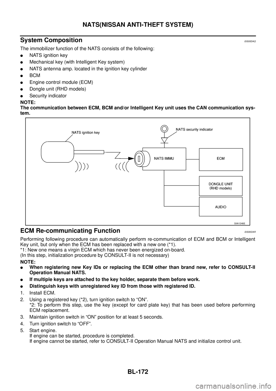
The immobilizer function of the NATS consists of the following:
lNATS ignition key
lMechanical key (with Intelligent Key system)
lNATS antenna amp. located in the ignition key cylinder
lBCM
lEngine control module (ECM)
lDongle unit (RHD models)
lSecurity indicator
NOTE:
The communication between ECM, BCM and/or Intelligent Key unit uses the CAN communication sys-
tem.
ECM Re-communicating FunctionEIS00DAR
Performing following procedure can automatically perform re-communication of ECM and BCM or Intelligent
Key unit, but only when the ECM has been replaced with a new one (*1).
*1: New one means a virgin ECM which has never been energized on-board.
(In this step, initialization procedure by CONSULT-II is not necessary)
NOTE:
lWhen registering new Key IDs or replacing the ECM other than brand new, refer to CONSULT-II
Operation Manual NATS.
lIf multiple keys are attached to the key holder, separate them before work.
lDistinguish keys with unregistered key ID from those with registered ID.
1. Install ECM.
2. Usingaregisteredkey(*2),turnignitionswitchto“ON”.
*2: To perform this step, use the key (except for card plate key) that has been used before performing
ECM replacement.
3. Maintain ignition switch in “ON” position for at least 5 seconds.
4. Turn ignition switch to “OFF”.
5. Start engine.
If engine can be started, procedure is completed.
If engine cannot be started, refer to CONSULT-II Operation Manual NATS and initialize control unit.
SIIA1246E
Page 758 of 3171
BL-174
NATS(NISSAN ANTI-THEFT SYSTEM)
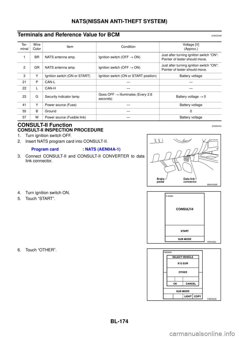
Terminals and Reference Value for BCM
EIS00DAW
CONSULT-II FunctionEIS00DAX
CONSULT-II INSPECTION PROCEDURE
1. Turn ignition switch OFF.
2. Insert NATS program card into CONSULT-II.
3. Connect CONSULT-II and CONSULT-II CONVERTER to data
link connector.
4. Turn ignition switch ON.
5. Touch “START”.
6. Touch “OTHER”.
Te r -
minalWire
ColorItem ConditionVoltag e [V]
(Approx.)
1 BR NATS antenna amp. Ignition switch (OFF®ON)Just after turning ignition switch “ON”:
Pointer of tester should move.
2 GR NATS antenna amp. Ignition switch (OFF®ON)Just after turning ignition switch “ON”:
Pointer of tester should move.
3 Y Ignition switch (ON or START) Ignition switch (ON or START position) Battery voltage
21 P CAN-L — —
22 L CAN-H — —
23 G Security indicator lampGoes OFF®illuminates (Every 2.6
seconds)Battery voltage®0
41 Y Power source (Fuse) — Battery voltage
55 B Ground — 0
57 W Power source (Fusible link) — Battery voltage
Program card : NATS (AEN04A-1)
BBIA0538E
PBR455D
PIIB0900E