Page 685 of 3171
MULTI-REMOTE CONTROL SYSTEM
BL-101
C
D
E
F
G
H
J
K
L
MA
B
BL
Terminals and Reference Value for BCMEIS00DBI
*: Double cab modelsTerminalWire
ColorItem ConditionVoltage (V)
(Approx.)
3 Y Ignition switch ON or START Ignition switch ON or START Battery voltage
4 V Ignition switch ACC or ON Ignition switch ACC or ON Battery voltage
5RKeyswitchON (Key is inserted in key cylinder) Battery voltage
OFF (Key is removed from key cylinder) 0
12* L Rear door switch RHON (door open) 0
OFF (door closed) Battery voltage
14 LGFront door switch
(Passenger side)ON (door open) 0
OFF (door closed) Battery voltage
15 SBFront door switch
(Driver side)ON (door open) 0
OFF (door closed) Battery voltage
16* P Rear door switch LHON (door open) 0
OFF (door closed) Battery voltage
21 P CAN L — —
22 L CAN H — —
41 Y Power source (Fuse) — Battery voltage
55 B Ground — 0
57 W Power source (Fusible link) — Battery voltage
Page 686 of 3171
BL-102
MULTI-REMOTE CONTROL SYSTEM
CONSULT-II Function (BCM)
EIS00DBJ
CONSULT-II can display each diagnostic item using the diagnostic test modes shown following.
CONSULT-II Inspection ProcedureEIS00DBK
“MULTI REMOTE ENT”
CAUTION:
If CONSULT-II is used with no connection of CONSULT-II CONVERTER, malfunctions might be
detected in self-diagnosis depending on control unit which carry out CAN communication.
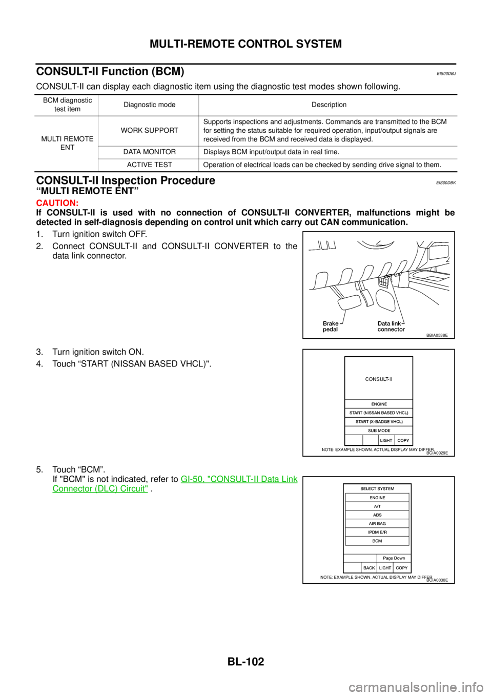
1. Turn ignition switch OFF.
2. Connect CONSULT-II and CONSULT-II CONVERTER to the
data link connector.
3. Turn ignition switch ON.
4. Touch “START (NISSAN BASED VHCL)".
5. Touch “BCM”.
If "BCM" is not indicated, refer toGI-50, "
CONSULT-II Data Link
Connector (DLC) Circuit".
BCM diagnostic
test itemDiagnostic mode Description
MULTI REMOTE
ENTWORK SUPPORTSupports inspections and adjustments. Commands are transmitted to the BCM
for setting the status suitable for required operation, input/output signals are
received from the BCM and received data is displayed.
DATA MONITOR Displays BCM input/output data in real time.
ACTIVE TEST Operation of electrical loads can be checked by sending drive signal to them.
BBIA0538E
BCIA0029E
BCIA0030E
Page 687 of 3171

MULTI-REMOTE CONTROL SYSTEM
BL-103
C
D
E
F
G
H
J
K
L
MA
B
BL
6. Touch “MULTI REMOTE ENT”.
7. Select diagnosis mode.
“DATA MONITOR”, “ACTIVE TEST” and “WORK SUPPORT”
are available.
CONSULT-II Application ItemsEIS00DBL
“MULTI REMOTE ENT”
Data Monitor
Active Test
LIIA0194E
BCIA0031E
Monitored Item Description
DOOR SW-AS Indicates [ON/OFF] condition of front door switch passenger side.
DOOR SW-RR Indicates [ON/OFF] condition of rear door switch RH.
DOOR SW-RL Indicates [ON/OFF] condition of rear door switch LH.
DOOR SW-DR Indicates [ON/OFF] condition of front door switch driver side.
BACK DOOR SW Indicates [ON/OFF] condition of back door switch.
KEY ON SW Indicates [ON/OFF] condition of key switch.
ACC ON SW Indicates [ON/OFF] condition of ignition switch in ACC position.
IGN ON SW Indicates [ON/OFF] condition of ignition switch in ON position.
KEYLESS PANIC This is display even when it is not equipped.
KEYLESS UNLOCK Indicates [ON/OFF] condition of unlock signal from keyfob.
KEYLESS LOCK Indicates [ON/OFF] condition of lock signal from keyfob.
KEY CYL LK-SW Indicates [ON/OFF] condition of lock signal from door key cylinder switch.
CDL UNLOCK SW Indicates [ON/OFF] condition of unlock signal from lock/unlock switch.
CDL LOCK SW Indicates [ON/OFF] condition of lock signal from lock/unlock switch.
RKE LCK-UNLCK Indicates [ON/OFF] condition of lock/unlock signal at the same time from keyfob.
RKE KEEP UNLK Indicates [ON/OFF] condition of unlock signal from keyfob.
TRNK OPEN MNTR This is display even when it is not equipped.
Test Item Description
FLASHERThis test is able to check right and left hazard reminder operation. The right hazard lamp turns on
when “RH” on CONSULT-II screen is touched and the left hazard lamp turns on when "LH" on CON-
SULT-II screen is touched.
DOOR LOCKThis test is able to check door lock operation. The doors lock and unlock based on the item on CON-
SULT-II screen is touched.
Page 689 of 3171
MULTI-REMOTE CONTROL SYSTEM
BL-105
C
D
E
F
G
H
J
K
L
MA
B
BL
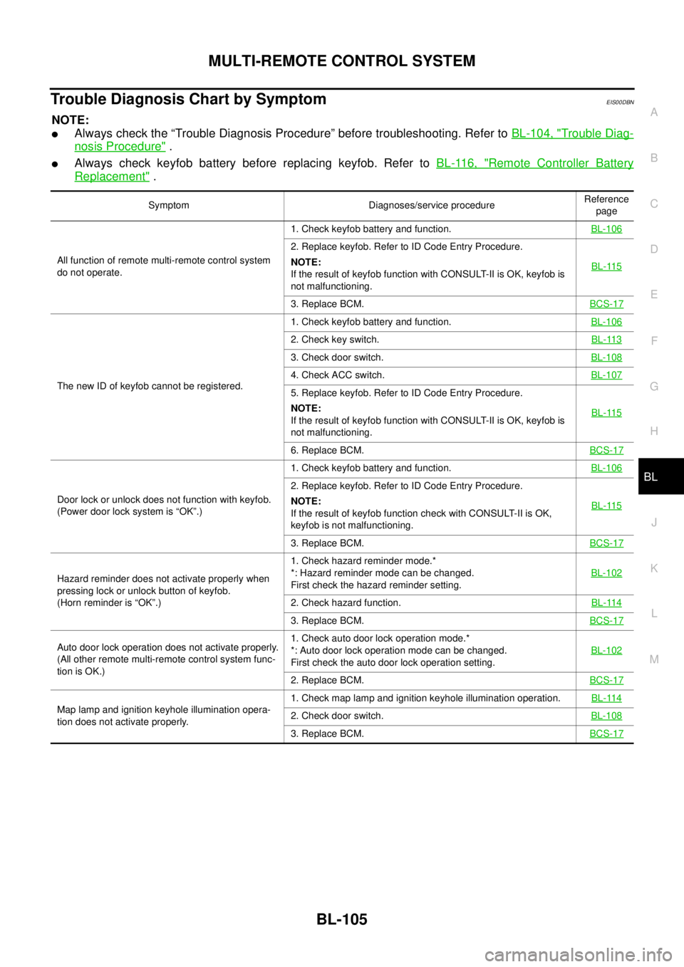
Trouble Diagnosis Chart by SymptomEIS00DBN
NOTE:
lAlways check the “Trouble Diagnosis Procedure” before troubleshooting. Refer toBL-104, "Trouble Diag-
nosis Procedure".
lAlways check keyfob battery before replacing keyfob. Refer toBL-116, "Remote Controller Battery
Replacement".
Symptom Diagnoses/service procedureReference
page
All function of remote multi-remote control system
do not operate.1. Check keyfob battery and function.BL-106
2. Replace keyfob. Refer to ID Code Entry Procedure.
NOTE:
If the result of keyfob function with CONSULT-II is OK, keyfob is
not malfunctioning.BL-115
3. Replace BCM.BCS-17
The new ID of keyfob cannot be registered.1. Check keyfob battery and function.BL-106
2. Check key switch.BL-113
3. Check door switch.BL-108
4. Check ACC switch.BL-107
5. Replace keyfob. Refer to ID Code Entry Procedure.
NOTE:
If the result of keyfob function with CONSULT-II is OK, keyfob is
not malfunctioning.BL-115
6. Replace BCM.BCS-17
Door lock or unlock does not function with keyfob.
(Power door lock system is “OK”.)1. Check keyfob battery and function.BL-106
2. Replace keyfob. Refer to ID Code Entry Procedure.
NOTE:
If the result of keyfob function check with CONSULT-II is OK,
keyfob is not malfunctioning.BL-115
3. Replace BCM.BCS-17
Hazard reminder does not activate properly when
pressing lock or unlock button of keyfob.
(Horn reminder is “OK”.)1. Check hazard reminder mode.*
*: Hazard reminder mode can be changed.
First check the hazard reminder setting.BL-102
2. Check hazard function.BL-114
3. Replace BCM.BCS-17
Auto door lock operation does not activate properly.
(All other remote multi-remote control system func-
tion is OK.)1. Check auto door lock operation mode.*
*: Auto door lock operation mode can be changed.
First check the auto door lock operation setting.BL-102
2. Replace BCM.BCS-17
Map lamp and ignition keyhole illumination opera-
tion does not activate properly.1. Check map lamp and ignition keyhole illumination operation.BL-1142. Check door switch.BL-108
3. Replace BCM.BCS-17
Page 691 of 3171
MULTI-REMOTE CONTROL SYSTEM
BL-107
C
D
E
F
G
H
J
K
L
MA
B
BL
Check ACC SwitchEIS00DBP
1.CHECK ACC SWITCH
With CONSULT-II
Check ACC switch (“ACC ON SW”) in “DATA MONITOR” mode with CONSULT-II.
Without CONSULT-II
Check voltage between fuse block (J/B) connector and ground.
OK or NG
OK >> ACC switch is OK.
NG >> Check the following.
l10A fuse [No. 4, located in the fuse block (J/B)]
lHarness for open or short between BCM and fuse block (J/B)
Monitor item Condition
ACC ON SWIgnition switch position is ACC or ON : ON
Ignition switch position is OFF : OFF
PIIA3367E
ConnectorTerminal
Ignition switch
positionVoltage [V]
(Approx.)
(+) (–)
M88 4A GroundACC Battery voltage
OFF 0
MIIB0772E
Page 692 of 3171
BL-108
MULTI-REMOTE CONTROL SYSTEM
Check Door Switch
EIS00DBQ
CHECK DOOR SWITCH (DOUBLE CAB)
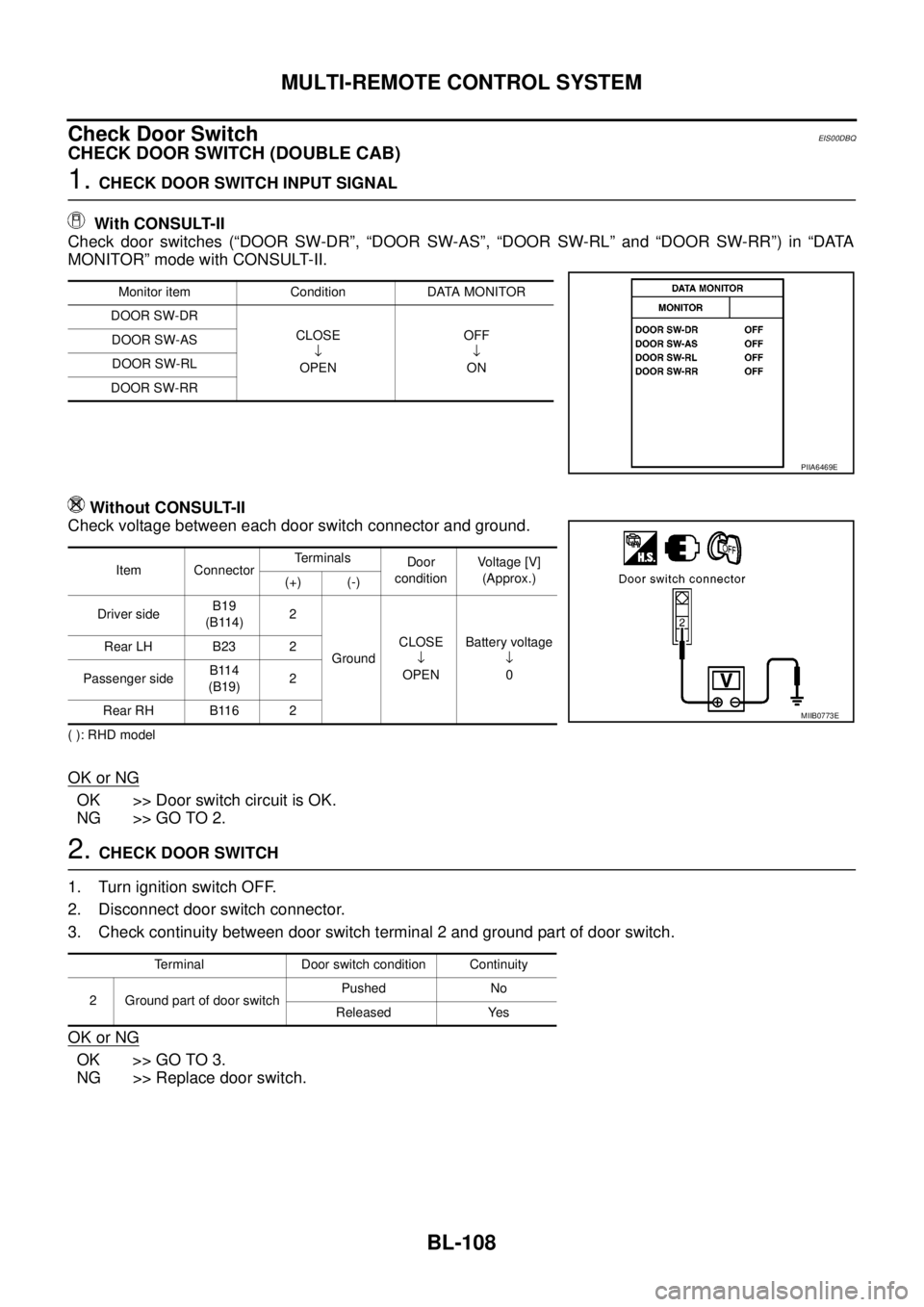
1.CHECK DOOR SWITCH INPUT SIGNAL
With CONSULT-II
Check door switches (“DOOR SW-DR”, “DOOR SW-AS”, “DOOR SW-RL” and “DOOR SW-RR”) in “DATA
MONITOR” mode with CONSULT-II.
Without CONSULT-II
Check voltage between each door switch connector and ground.
( ): RHD model
OK or NG
OK >> Door switch circuit is OK.
NG >> GO TO 2.
2.CHECK DOOR SWITCH
1. Turn ignition switch OFF.
2. Disconnect door switch connector.
3. Check continuity between door switch terminal 2 and ground part of door switch.
OK or NG
OK >> GO TO 3.
NG >> Replace door switch.
Monitor item Condition DATA MONITOR
DOOR SW-DR
CLOSE
¯
OPENOFF
¯
ON DOOR SW-AS
DOOR SW-RL
DOOR SW-RR
PIIA6469E
Item ConnectorTerminals
Door
conditionVoltage [V]
(Approx.)
(+) (-)
Driver sideB19
(B114)2
GroundCLOSE
¯
OPENBattery voltage
¯
0 Rear LH B23 2
Passenger sideB114
(B19)2
Rear RH B116 2
MIIB0773E
Terminal Door switch condition Continuity
2 Ground part of door switchPushed No
Released Yes
Page 695 of 3171
MULTI-REMOTE CONTROL SYSTEM
BL-111
C
D
E
F
G
H
J
K
L
MA
B
BL
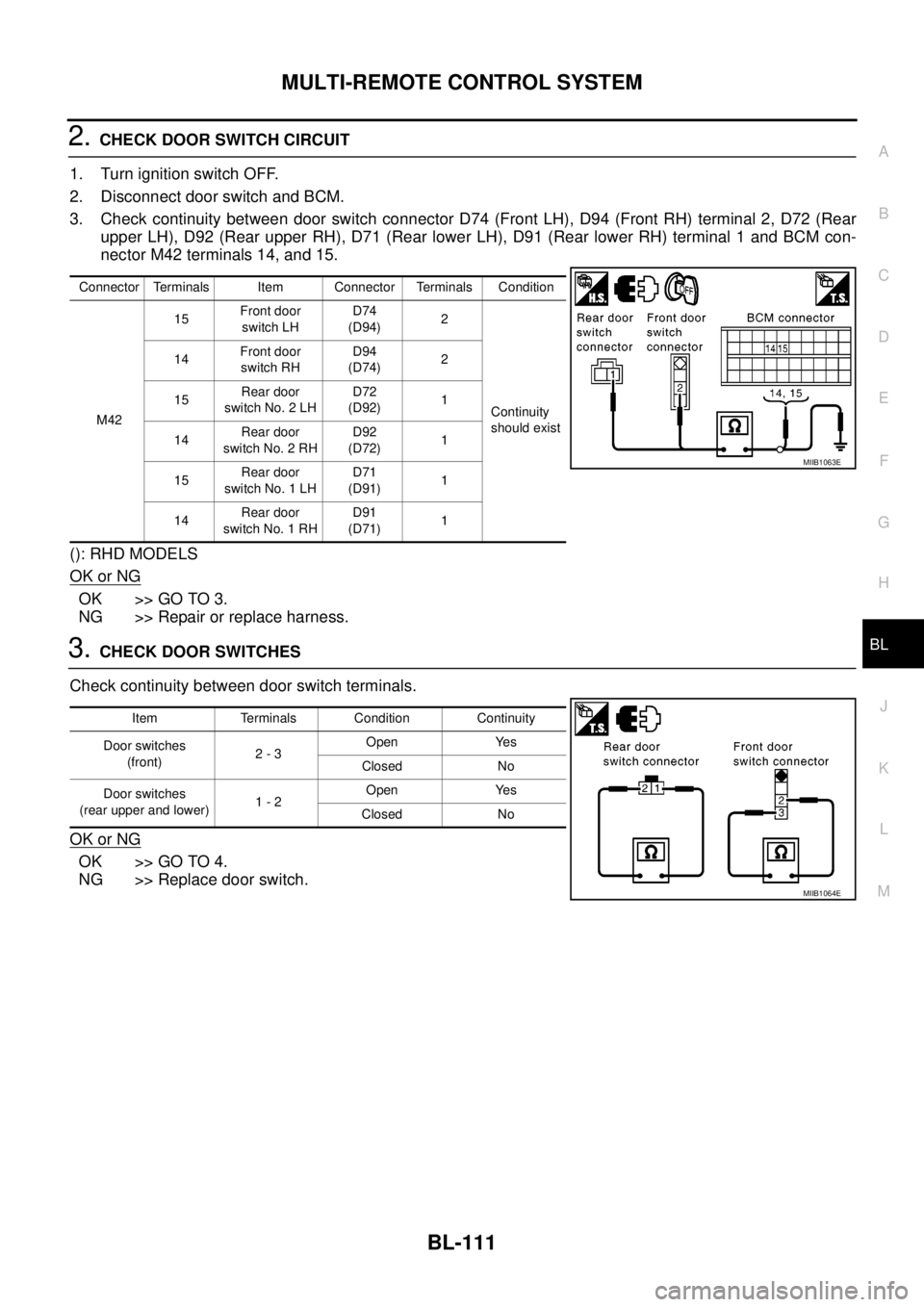
2.CHECK DOOR SWITCH CIRCUIT
1. Turn ignition switch OFF.
2. Disconnect door switch and BCM.
3. Check continuity between door switch connector D74 (Front LH), D94 (Front RH) terminal 2, D72 (Rear
upper LH), D92 (Rear upper RH), D71 (Rear lower LH), D91 (Rear lower RH) terminal 1 and BCM con-
nector M42 terminals 14, and 15.
(): RHD MODELS
OK or NG
OK >> GO TO 3.
NG >> Repair or replace harness.
3.CHECK DOOR SWITCHES
Check continuity between door switch terminals.
OK or NG
OK >> GO TO 4.
NG >> Replace door switch.
Connector Terminals Item Connector Terminals Condition
M4215Front door
switch LHD74
(D94)2
Continuity
should exist 14Front door
switch RHD94
(D74)2
15Rear door
switch No. 2 LHD72
(D92)1
14Rear door
switch No. 2 RHD92
(D72)1
15Rear door
switch No. 1 LHD71
(D91)1
14Rear door
switch No. 1 RHD91
(D71)1
MIIB1063E
Item Terminals Condition Continuity
Door switches
(front)2-3Open Yes
Closed No
Door switches
(rear upper and lower)1-2Open Yes
Closed No
MIIB1064E
Page 697 of 3171
MULTI-REMOTE CONTROL SYSTEM
BL-113
C
D
E
F
G
H
J
K
L
MA
B
BL
Check Key SwitchEIS00DBR
1.CHECK KEY SWITCH INPUT SIGNAL
With CONSULT-II
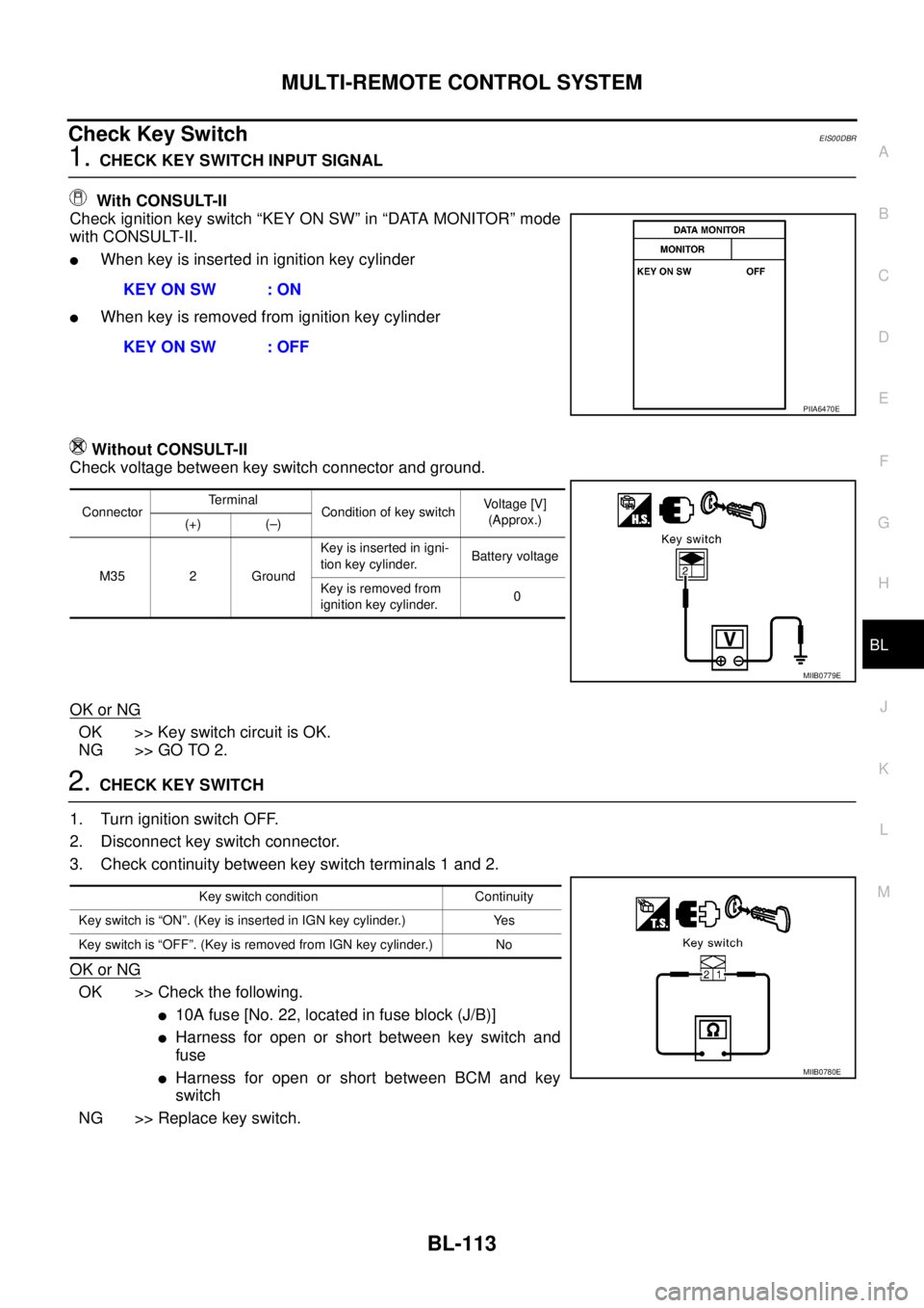
Check ignition key switch “KEY ON SW” in “DATA MONITOR” mode
with CONSULT-II.
lWhen key is inserted in ignition key cylinder
lWhen key is removed from ignition key cylinder
Without CONSULT-II
Check voltage between key switch connector and ground.
OK or NG
OK >> Key switch circuit is OK.
NG >> GO TO 2.
2.CHECK KEY SWITCH
1. Turn ignition switch OFF.
2. Disconnect key switch connector.
3. Check continuity between key switch terminals 1 and 2.
OK or NG
OK >> Check the following.
l10Afuse[No.22,locatedinfuseblock(J/B)]
lHarness for open or short between key switch and
fuse
lHarness for open or short between BCM and key
switch
NG >> Replace key switch.KEY ON SW : ON
KEY ON SW : OFF
PIIA6470E
ConnectorTerminal
Condition of key switchVo l ta g e [V ]
(Approx.)
(+) (–)
M35 2 GroundKey is inserted in igni-
tion key cylinder.Battery voltage
Key is removed from
ignition key cylinder.0
MIIB0779E
Key switch condition Continuity
Key switch is “ON”. (Key is inserted in IGN key cylinder.) Yes
Key switch is “OFF”. (Key is removed from IGN key cylinder.) No
MIIB0780E