2005 NISSAN NAVARA warning
[x] Cancel search: warningPage 2291 of 3171
MA-16
RECOMMENDED FLUIDS AND LUBRICANTS
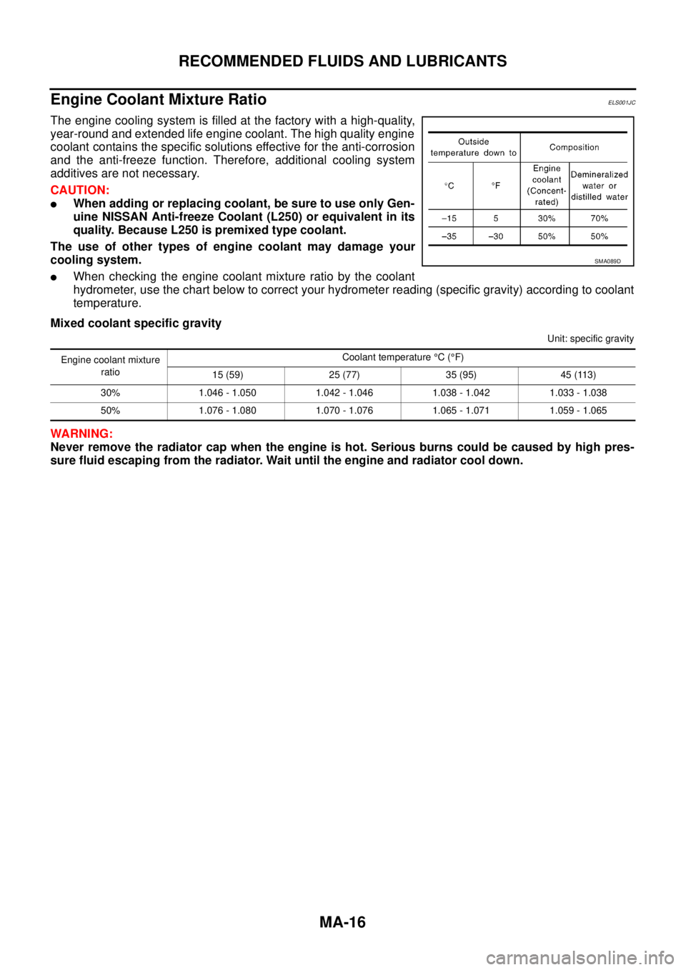
Engine Coolant Mixture Ratio
ELS001JC
The engine cooling system is filled at the factory with a high-quality,
year-round and extended life engine coolant. The high quality engine
coolant contains the specific solutions effective for the anti-corrosion
and the anti-freeze function. Therefore, additional cooling system
additives are not necessary.
CAUTION:
lWhen adding or replacing coolant, be sure to use only Gen-
uine NISSAN Anti-freeze Coolant (L250) or equivalent in its
quality. Because L250 is premixed type coolant.
The use of other types of engine coolant may damage your
cooling system.
lWhen checking the engine coolant mixture ratio by the coolant
hydrometer, use the chart below to correct your hydrometer reading (specific gravity) according to coolant
temperature.
Mixed coolant specific gravity
Unit: specific gravity
WARNING:
Never remove the radiator cap when the engine is hot. Serious burns could be caused by high pres-
sure fluid escaping from the radiator. Wait until the engine and radiator cool down.
SMA089D
Engine coolant mixture
ratioCoolant temperature°C(°F)
15 (59) 25 (77) 35 (95) 45 (113)
30% 1.046 - 1.050 1.042 - 1.046 1.038 - 1.042 1.033 - 1.038
50% 1.076 - 1.080 1.070 - 1.076 1.065 - 1.071 1.059 - 1.065
Page 2294 of 3171
ENGINE MAINTENANCE
MA-19
C
D
E
F
G
H
I
J
K
MA
B
MA
A/C COMPRESSOR, ALTERNATOR AND WATER PUMP BELT
1. Loosen idler pulley lock nut (D).
2. Turn adjusting nut (C) to adjust. Refer toMA-18, "
Deflection Adjustment".
3. Tighten lock nut (D).
Changing Engine CoolantELS001JQ
WARNING:
lTo avoid being scalded, do not change engine coolant when engine is hot.
lWrap a thick cloth around cap and carefully remove radiator cap. First, turn radiator cap a quarter
of a turn to release built-up pressure. Then turn the cap all the way.
DRAINING ENGINE COOLANT
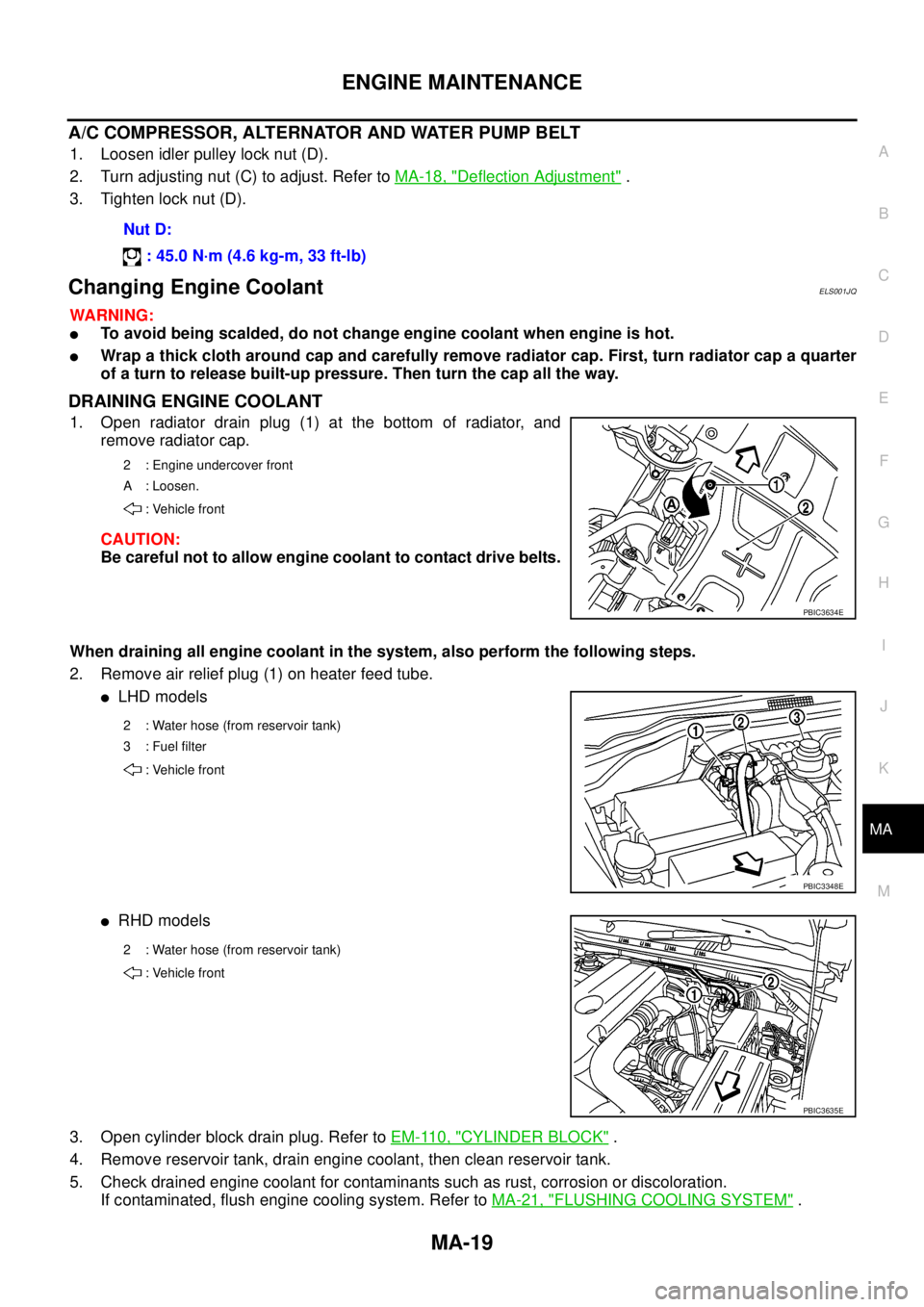
1. Open radiator drain plug (1) at the bottom of radiator, and
remove radiator cap.
CAUTION:
Be careful not to allow engine coolant to contact drive belts.
When draining all engine coolant in the system, also perform the following steps.
2. Remove air relief plug (1) on heater feed tube.
lLHD models
lRHD models
3. Open cylinder block drain plug. Refer toEM-110, "
CYLINDER BLOCK".
4. Remove reservoir tank, drain engine coolant, then clean reservoir tank.
5. Check drained engine coolant for contaminants such as rust, corrosion or discoloration.
If contaminated, flush engine cooling system. Refer toMA-21, "
FLUSHING COOLING SYSTEM". Nut D:
: 45.0 N·m (4.6 kg-m, 33 ft-lb)
2 : Engine undercover front
A : Loosen.
: Vehicle front
PBIC3634E
2 : Water hose (from reservoir tank)
3:Fuelfilter
: Vehicle front
PBIC3348E
2 : Water hose (from reservoir tank)
: Vehicle front
PBIC3635E
Page 2296 of 3171
ENGINE MAINTENANCE
MA-21
C
D
E
F
G
H
I
J
K
MA
B
MA
11. Repeat step 10 three times.
12. If sound is heard, bleed air from cooling system by repeating steps 3 through 6 until engine coolant level
no longer drops.
FLUSHING COOLING SYSTEM
1. Fill radiator with water until water spills from the air relief hole, then close air relief plug. Fill radiator and
reservoir tank with water and reinstall radiator cap and reservoir tank cap.
2. Run engine and warm it up to normal operating temperature.
3. Rev engine two or three times under no-load.
4. Stop engine and wait until it cools down.
5. Drain water from the system. Refer toMA-19, "
DRAINING ENGINE COOLANT".
6. Repeat steps 1 through 5 until clear water begins to drain from radiator.
Checking Cooling SystemELS001JR
WARNING:
Never remove the radiator cap and reservoir tank cap when the engine is hot. Serious burns could
occur from high pressure engine coolant escaping from the radiator and the reservoir tank. Wrap a
thick cloth around the cap. Slowly turn it a quarter turn to allow built-up pressure to escape. Carefully
remove the cap by turning it all the way.
CHECKING COOLING SYSTEM HOSES
Check hoses for improper attachment, leaks, cracks, damage, loose connections, chafing and deterioration.
CHECKING RADIATOR
Check radiator for mud or clogging. If necessary, clean radiator as follows.
lBe careful not to bend or damage the radiator fins.
lWhen radiator is cleaned without removal, remove all surrounding parts such as cooling fan, radiator
shroud and horns. Then tape the harness and connectors to prevent water from entering.
1. Apply water by hose to the back side of the radiator core vertically downwards.
2. Apply water again to all radiator core surface once per minute.
3. Stop washing if any stains no longer flow out from the radiator.
4. Blow air into the back side of radiator core vertically downwards.
lUse compressed air lower than 490 kpa (4.9 bar, 5 kg/cm2, 71psi) and keep distance more than 30
cm(11.8 in).
5. Blow air again into all the radiator core surface once per minute until no water sprays out.
CHECKING RESERVOIR TANK CAP
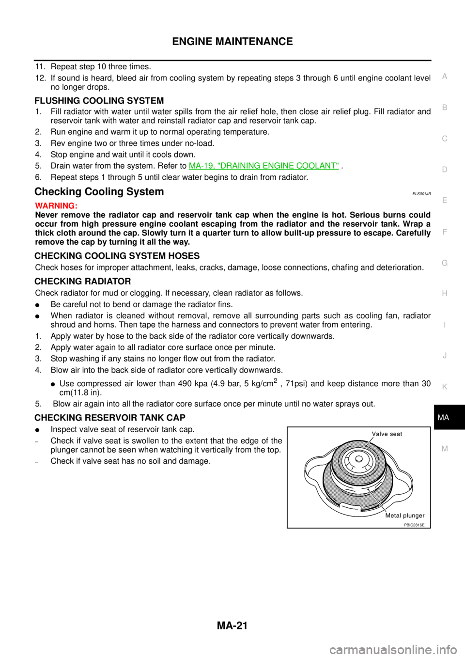
lInspect valve seat of reservoir tank cap.
–Check if valve seat is swollen to the extent that the edge of the
plunger cannot be seen when watching it vertically from the top.
–Check if valve seat has no soil and damage.
PBIC2816E
Page 2297 of 3171
MA-22
ENGINE MAINTENANCE
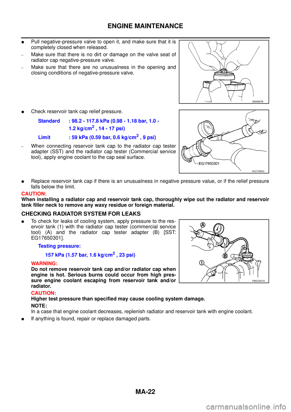
lPull negative-pressure valve to open it, and make sure that it is
completely closed when released.
–Makesurethatthereisnodirtordamageonthevalveseatof
radiator cap negative-pressure valve.
–Make sure that there are no unusualness in the opening and
closing conditions of negative-pressure valve.
lCheck reservoir tank cap relief pressure.
–When connecting reservoir tank cap to the radiator cap tester
adapter (SST) and the radiator cap tester (Commercial service
tool), apply engine coolant to the cap seal surface.
lReplace reservoir tank cap if there is an unusualness in negative pressure value, or if the relief pressure
falls below the limit.
CAUTION:
When installing a radiator cap and reservoir tank cap, thoroughly wipe out the radiator and reservoir
tank filler neck to remove any waxy residue or foreign material.
CHECKING RADIATOR SYSTEM FOR LEAKS
lTo check for leaks of cooling system, apply pressure to the res-
ervoir tank (1) with the radiator cap tester (commercial service
tool) (A) and the radiator cap tester adapter (B) [SST:
EG17650301].
WARNING:
Do not remove reservoir tank cap and/or radiator cap when
engine is hot. Serious burns could occur from high pres-
sure engine coolant escaping from reservoir tank and/or
radiator.
CAUTION:
Higher test pressure than specified may cause cooling system damage.
NOTE:
In a case that engine coolant decreases, replenish radiator and reservoir tank with engine coolant.
lIf anything is found, repair or replace damaged parts.
SMA967B
Standard : 98.2 - 117.8 kPa (0.98 - 1.18 bar, 1.0 -
1.2 kg/cm
2,14-17psi)
Limit : 59 kPa (0.59 bar, 0.6 kg/cm
2,9psi)
SLC755AC
Testing pressure:
157 kPa (1.57 bar, 1.6 kg/cm
2,23psi)
PBIC3501E
Page 2300 of 3171
ENGINE MAINTENANCE
MA-25
C
D
E
F
G
H
I
J
K
MA
B
MA
Draining Water from Fuel FilterELS001JU
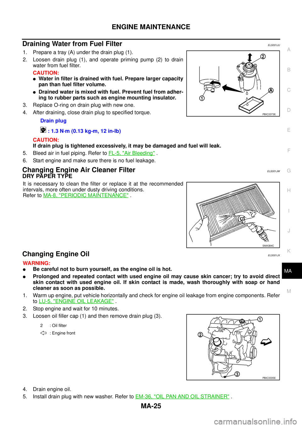
1. Prepare a tray (A) under the drain plug (1).
2. Loosen drain plug (1), and operate priming pump (2) to drain
water from fuel filter.
CAUTION:
lWater in filter is drained with fuel. Prepare larger capacity
pan than fuel filter volume.
lDrained water is mixed with fuel. Prevent fuel from adher-
ing to rubber parts such as engine mounting insulator.
3. Replace O-ring on drain plug with new one.
4. After draining, close drain plug to specified torque.
CAUTION:
If drain plug is tightened excessively, it may be damaged and fuel will leak.
5. Bleed air in fuel piping. Refer toFL-5, "
Air Bleeding".
6. Start engine and make sure there is no fuel leakage.
Changing Engine Air Cleaner FilterELS001JW
DRY PAPER TYPE
It is necessary to clean the filter or replace it at the recommended
intervals, more often under dusty driving conditions.
Refer toMA-8, "
PERIODIC MAINTENANCE".
Changing Engine OilELS001JX
WARNING:
lBe careful not to burn yourself, as the engine oil is hot.
lProlonged and repeated contact with used engine oil may cause skin cancer; try to avoid direct
skin contact with used engine oil. If skin contact is made, wash thoroughly with soap or hand
cleaner as soon as possible.
1. Warm up engine, put vehicle horizontally and check for engine oil leakage from engine components. Refer
toLU-5, "
ENGINE OIL LEAKAGE".
2. Stop engine and wait for 10 minutes.
3. Loosen oil filler cap (1) and then remove drain plug (3).
4. Drain engine oil.
5. Install drain plug with new washer. Refer toEM-36, "
OIL PAN AND OIL STRAINER". Drain plug
: 1.3 N·m (0.13 kg-m, 12 in-lb)
PBIC3373E
SMA384C
2 : Oil filter
: Engine front
PBIC3335E
Page 2310 of 3171
CHASSIS AND BODY MAINTENANCE
MA-35
C
D
E
F
G
H
I
J
K
MA
B
MA
Checking Brake Fluid Level and LeaksELS001IZ
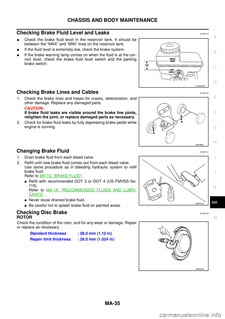
lCheck the brake fluid level in the reservoir tank. It should be
between the “MAX” and “MIN” lines on the reservoir tank.
lIf the fluid level is extremely low, check the brake system.
lIf the brake warning lamp comes on when the fluid is at the cor-
rect level, check the brake fluid level switch and the parking
brake switch.
Checking Brake Lines and CablesELS001J0
1. Check the brake lines and hoses for cracks, deterioration, and
other damage. Replace any damaged parts.
CAUTION:
If brake fluid leaks are visible around the brake line joints,
retighten the joint, or replace damaged parts as necessary.
2. Check for brake fluid leaks by fully depressing brake pedal while
engine is running.
Changing Brake FluidELS001J1
1. Drain brake fluid from each bleed valve.
2. Refill until new brake fluid comes out from each bleed valve.
Use same procedure as in bleeding hydraulic system to refill
brake fluid.
Refer toBR-10, "
BRAKE FLUID".
lRefill with recommended DOT 3 or DOT 4 (US FMVSS No.
11 6 ) .
Refer toMA-14, "
RECOMMENDED FLUIDS AND LUBRI-
CANTS".
lNever reuse drained brake fluid.
lBe careful not to splash brake fluid on painted areas.
Checking Disc BrakeELS001J2
ROTOR
Check the condition of the rotor, and for any wear or damage. Repair
or replace as necessary.
LFIA0234E
SBR389C
SBR419C
Standard thickness : 28.0 mm (1.12 in)
Repair limit thickness : 26.0 mm (1.024 in)
SMA260A
Page 2391 of 3171
MTC-4
PRECAUTIONS
PRECAUTIONS
PFP:00001
Precautions for Supplemental Restraint System (SRS) “AIR BAG” and “SEAT
BELT PRE-TENSIONER”
EJS005QE
The Supplemental Restraint System such as “AIR BAG” and “SEAT BELT PRE-TENSIONER”, used along
with a front seat belt, helps to reduce the risk or severity of injury to the driver and front passenger for certain
types of collision. Information necessary to service the system safely is included in the SRS and SB section of
this Service Manual.
WARNING:
lTo avoid rendering the SRS inoperative, which could increase the risk of personal injury or death
in the event of a collision which would result in air bag inflation, all maintenance must be per-
formed by an authorized NISSAN/INFINITI dealer.
lImproper maintenance, including incorrect removal and installation of the SRS, can lead to per-
sonal injury caused by unintentional activation of the system. For removal of Spiral Cable and Air
Bag Module, see the SRS section.
lDo not use electrical test equipment on any circuit related to the SRS unless instructed to in this
Service Manual. SRS wiring harnesses can be identified by yellow and/or orange harnesses or
harness connectors.
Precautions for Working with HFC-134a (R-134a)EJS00627
WARNING:
lCFC-12 (R-12) refrigerant and HFC-134a (R-134a) refrigerant are not compatible. These refrigerants
must never be mixed, even in the smallest amounts. If the refrigerants are mixed and compressor
malfunction is likely occur.
lUse only specified lubricant for the HFC-134a (R-134a) A/C system and HFC-134a (R-134a) compo-
nents. If lubricant other than that specified is used, compressor malfunction is likely to occur.
lThe specified HFC-134a (R-134a) lubricant rapidly absorbs moisture from the atmosphere. The fol-
lowing handling precautions must be observed:
–When removing refrigerant components from a vehicle, immediately cap (seal) the component to
minimize the entry of moisture from the atmosphere.
–When installing refrigerant components to a vehicle, do not remove the caps (unseal) until just
before connecting the components. Connect all refrigerant loop components as quickly as possi-
ble to minimize the entry of moisture into system.
–Only use the specified lubricant from a sealed container. Immediately reseal containers of lubri-
cant. Without proper sealing, lubricant will become moisture saturated and should not be used.
–Avoid breathing A/C refrigerant and lubricant vapor or mist. Exposure may irritate eyes, nose and
throat. Use only approved recovery/recycling equipment to discharge HFC-134a (R-134a) refriger-
ant. If accidental system discharge occurs, ventilate work area before resuming service. Addi-
tional health and safety information may be obtained from refrigerant and lubricant
manufacturers.
–Do not allow lubricant (Nissan A/C System Oil Type S) to come in contact with styrofoam parts.
Damage may result.
Contaminated RefrigerantEJS0063C
If a refrigerant other than pure HFC-134a (R-134a) is identified in a vehicle, your options are:
lExplain to the customer that environmental regulations prohibit the release of contaminated refrigerant
into the atmosphere.
lExplain that recovery of the contaminated refrigerant could damage your service equipment and refriger-
ant supply.
lSuggest the customer return the vehicle to the location of previous service where the contamination may
have occurred.
lIf you choose to perform the repair, recover the refrigerant using onlydedicated equipment and contain-
ers. Do not recover contaminated refrigerant into your existing service equipment.If your facility
does not have dedicated recovery equipment, you may contact a local refrigerant product retailer for avail-
able service. This refrigerant must be disposed of in accordance with all federal and local regulations. In
addition, replacement of all refrigerant system components on the vehicle is recommended.
Page 2392 of 3171
PRECAUTIONS
MTC-5
C
D
E
F
G
H
I
K
L
MA
B
MTC
lIf the vehicle is within the warranty period, the air conditioner warranty is void. Please contact NISSAN
Customer Affairs for further assistance.
General Refrigerant PrecautionsEJS00628
WARNING:
lDo not release refrigerant into the air. Use approved recovery/recycling equipment to capture the
refrigerant every time an air conditioning system is discharged.
lAlways wear eye and hand protection (goggles and gloves) when working with any refrigerant or
air conditioning system.
lDo not store or heat refrigerant containers above 52°C.
lDo not heat a refrigerant container with an open flame; if container warming is required, place the
bottom of the container in a warm pail of water.
lDo not intentionally drop, puncture, or incinerate refrigerant containers.
lKeep refrigerant away from open flames: poisonous gas will be produced if refrigerant burns.
lRefrigerant will displace oxygen, therefore be certain to work in well ventilated areas to prevent
suffocation.
lDo not pressure test or leak test HFC-134a (R-134a) service equipment and/or vehicle air condi-
tioning systems with compressed air during repair. Some mixtures of air and HFC-134a (R-134a)
have been shown to be combustible at elevated pressures. These mixtures, if ignited, may cause
injury or property damage. Additional health and safety information may be obtained from refriger-
ant manufacturers.
Precautions for Refrigerant ConnectionEJS005FL
A new type refrigerant connection has been introduced to all refrigerant lines except the following locations.
lExpansion valve to cooling unit
lEvaporator pipes to evaporator (inside cooling unit)
lRefrigerant pressure sensor
ABOUT ONE-TOUCH JOINT
Description
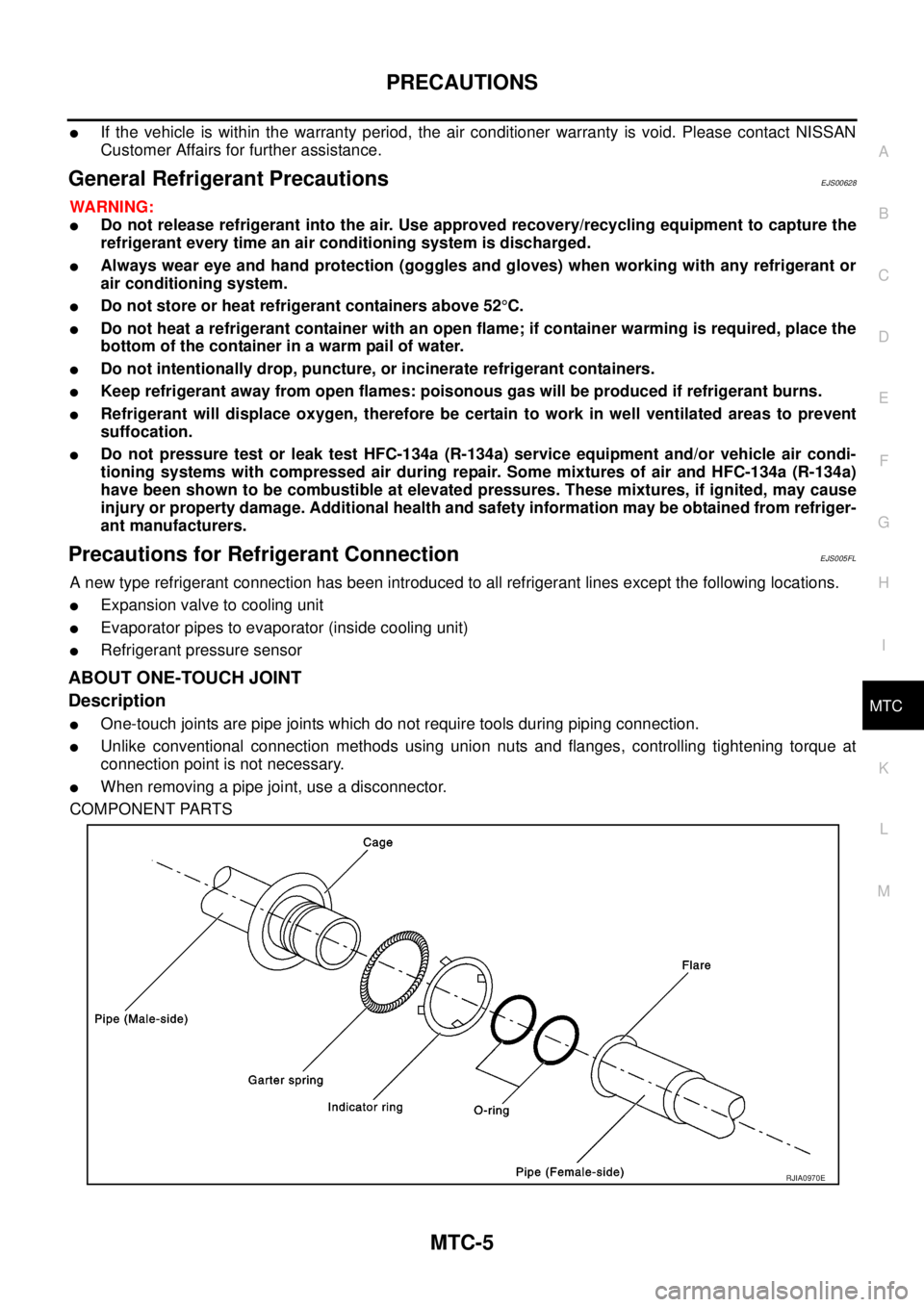
lOne-touch joints are pipe joints which do not require tools during piping connection.
lUnlike conventional connection methods using union nuts and flanges, controlling tightening torque at
connection point is not necessary.
lWhen removing a pipe joint, use a disconnector.
COMPONENT PARTS
RJIA0970E