2005 NISSAN NAVARA wheel torque
[x] Cancel search: wheel torquePage 1516 of 3171
EM-134
CYLINDER BLOCK
FLYWHEEL DEFLECTION
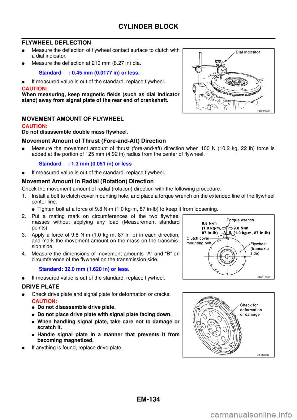
lMeasure the deflection of flywheel contact surface to clutch with
a dial indicator.
lMeasure the deflection at 210 mm (8.27 in) dia.
lIf measured value is out of the standard, replace flywheel.
CAUTION:
When measuring, keep magnetic fields (such as dial indicator
stand) away from signal plate of the rear end of crankshaft.
MOVEMENT AMOUNT OF FLYWHEEL
CAUTION:
Do not disassemble double mass flywheel.
Movement Amount of Thrust (Fore-and-Aft) Direction
lMeasure the movement amount of thrust (fore-and-aft) direction when 100 N (10.2 kg, 22 lb) force is
added at the portion of 125 mm (4.92 in) radius from the center of flywheel.
lIf measured value is out of the standard, replace flywheel.
Movement Amount in Radial (Rotation) Direction
Check the movement amount of radial (rotation) direction with the following procedure:
1. Install a bolt to clutch cover mounting hole, and place a torque wrench on the extended line of the flywheel
center line.
lTighten bolt at a force of 9.8 N·m (1.0 kg-m, 87 in-lb) to keep it from loosening.
2. Put a mating mark on circumferences of the two flywheel
masses without applying any load (Measurement standard
points).
3. Apply a force of 9.8 N·m (1.0 kg-m, 87 in-lb) in each direction,
and mark the movement amount on the mass on the transmis-
sion side.
4. Measure the dimensions of movement amounts “A” and “B” on
circumference of the flywheel on the transmission side.
lIf measured value is out of the standard, replace flywheel.
DRIVE PLATE
lCheck drive plate and signal plate for deformation or cracks.
CAUTION:
lDo not disassemble drive plate.
lDo not place drive plate with signal plate facing down.
lWhen handling signal plate, take care not to damage or
scratch it.
lHandle signal plate in a manner that prevents it from
becoming magnetized.
lIf anything is found, replace drive plate.Standard : 0.45 mm (0.0177 in) or less.
PBIC2646E
Standard : 1.3 mm (0.051 in) or less
Standard: 32.0 mm (1.620 in) or less.
PBIC1263E
SEM760G
Page 1537 of 3171
WHEEL HUB
FAX-5
C
E
F
G
H
I
J
K
L
MA
B
FA X
WHEEL HUBPFP:43202
On-Vehicle Inspection and ServiceEDS003I7
Make sure the mounting conditions (looseness, backlash) of each component and component status (wear,
damage) are normal.
WHEEL BEARING INSPECTION
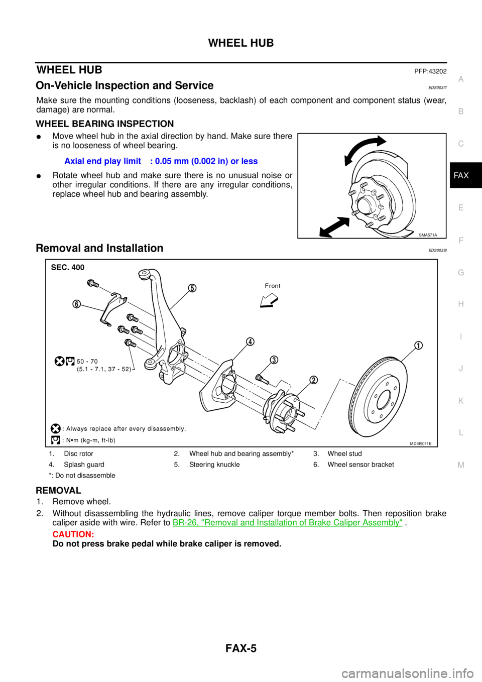
lMove wheel hub in the axial direction by hand. Make sure there
is no looseness of wheel bearing.
lRotate wheel hub and make sure there is no unusual noise or
other irregular conditions. If there are any irregular conditions,
replace wheel hub and bearing assembly.
Removal and InstallationEDS003I8
REMOVAL
1. Remove wheel.
2. Without disassembling the hydraulic lines, remove caliper torque member bolts. Then reposition brake
caliper aside with wire. Refer toBR-26, "
Removal and Installation of Brake Caliper Assembly".
CAUTION:
Do not press brake pedal while brake caliper is removed.Axial end play limit : 0.05 mm (0.002 in) or less
SMA571A
1. Disc rotor 2. Wheel hub and bearing assembly* 3. Wheel stud
4. Splash guard 5. Steering knuckle 6. Wheel sensor bracket
*: Do not disassemble
MDIB9011E
Page 1555 of 3171
FRONT OIL SEAL
FFD-9
C
E
F
G
H
I
J
K
L
MA
B
FFD
FRONT OIL SEALPFP:38189
Removal and InstallationEDS00353
CAUTION:
Verify identification stamp of replacement frequency put in the lower part of gear carrier to determine
replacement for collapsible spacer when replacing front oil seal. Refer toFFD-9, "
IDENTIFICATION
STAMP OF REPLACEMENT FREQUENCY OF FRONT OIL SEAL". If necessary collapsible spacer
replacement, remove final drive assembly and disassemble it to replace front oil seal and collapsible
spacer. Refer toFFD-15, "
Removal and Installation"andFFD-17, "Disassembly and Assembly".
NOTE:
The reuse of collapsible spacer is prohibited in principle. However, it is reusable on a one-time basis
only in cases when replacing front oil seal.
IDENTIFICATION STAMP OF REPLACEMENT FREQUENCY OF FRONT OIL SEAL
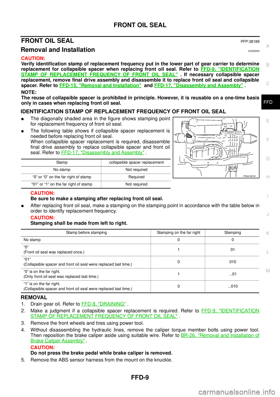
lThe diagonally shaded area in the figure shows stamping point
for replacement frequency of front oil seal.
lThe following table shows if collapsible spacer replacement is
needed before replacing front oil seal.
When collapsible spacer replacement is required, disassemble
final drive assembly to replace collapsible spacer and front oil
seal. Refer toFFD-17, "
Disassembly and Assembly".
CAUTION:
Be sure to make a stamping after replacing front oil seal.
lAfter replacing front oil seal, make a stamping on the stamping point in accordance with the table below in
order to identify replacement frequency.
CAUTION:
Stamping shall be made from left to right.
REMOVAL
1. Drain gear oil. Refer toFFD-8, "DRAINING".
2. Make a judgment if a collapsible spacer replacement is required. Refer toFFD-9, "
IDENTIFICATION
STAMP OF REPLACEMENT FREQUENCY OF FRONT OIL SEAL".
3. Remove the front wheels and tires using power tool.
4. Without disassembling the hydraulic lines, remove the caliper torque member bolts using power tool.
Then reposition the brake caliper aside using suitable wire. Refer toBR-26, "
Removal and Installation of
Brake Caliper Assembly".
CAUTION:
Do not press the brake pedal while brake caliper is removed.
5. Remove the ABS sensor harness from the mount on the knuckle.
Stamp collapsible spacer replacement
No stamp Not required
“0” or “0” on the far right of stamp Required
“01” or “1” on the far right of stamp Not required
PDIA1001E
Stamp before stamping Stamping on the far right Stamping
No stamp00
“0”
(Front oil seal was replaced once.)101
“01”
(Collapsible spacer and front oil seal were replaced last time.)0010
“0”isonthefarright.
(Only front oil seal was replaced last time.)1 ...01
“1”isonthefarright.
(Collapsible spacer and front oil seal were replaced last time.)0 ...010
Page 1558 of 3171
FFD-12
FRONT OIL SEAL
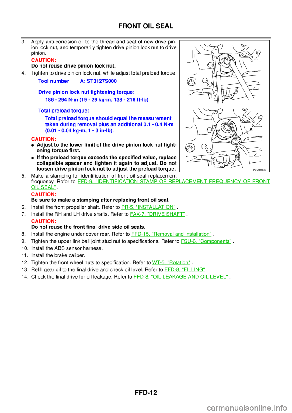
3. Apply anti-corrosion oil to the thread and seat of new drive pin-
ion lock nut, and temporarily tighten drive pinion lock nut to drive
pinion.
CAUTION:
Do not reuse drive pinion lock nut.
4. Tighten to drive pinion lock nut, while adjust total preload torque.
CAUTION:
lAdjust to the lower limit of the drive pinion lock nut tight-
ening torque first.
lIf the preload torque exceeds the specified value, replace
collapsible spacer and tighten it again to adjust. Do not
loosen drive pinion lock nut to adjust the preload torque.
5. Make a stamping for identification of front oil seal replacement
frequency. Refer toFFD-9, "
IDENTIFICATION STAMP OF REPLACEMENT FREQUENCY OF FRONT
OIL SEAL".
CAUTION:
Be sure to make a stamping after replacing front oil seal.
6. Install the front propeller shaft. Refer toPR-5, "
INSTALLATION".
7. Install the RH and LH drive shafts. Refer toFA X - 7 , "
DRIVE SHAFT".
CAUTION:
Do not reuse the front final drive side oil seals.
8. Install the engine under cover rear. Refer toFFD-15, "
Removal and Installation".
9. Tighten the upper link ball joint stud nut to specifications. Refer toFSU-6, "
Components".
10. Install the ABS sensor harness.
11. Install the brake caliper.
12. Tighten the front wheel nuts to specification. Refer toWT-5, "
Rotation".
13. Refill gear oil to the final drive and check oil level. Refer toFFD-8, "
FILLING".
14. Check the final drive for oil leakage. Refer toFFD-8, "
OIL LEAKAGE AND OIL LEVEL". Tool number A: ST3127S000
Drive pinion lock nut tightening torque:
186 - 294 N·m (19 - 29 kg-m, 138 - 216 ft-lb)
Total preload torque:
Total preload torque should equal the measurement
taken during removal plus an additional 0.1 - 0.4 N·m
(0.01 - 0.04 kg-m, 1 - 3 in-lb).
PDIA1003E
Page 1559 of 3171
SIDE OIL SEAL
FFD-13
C
E
F
G
H
I
J
K
L
MA
B
FFD
SIDE OIL SEALPFP:33142
Removal and InstallationEDS00354
REMOVAL
1. Remove the front wheels and tires using power tool.
2. Without disassembling the hydraulic lines, remove the caliper torque member bolts using power tool.
Then reposition the brake caliper aside using suitable wire. Refer toBR-26, "
Removal and Installation of
Brake Caliper Assembly".
CAUTION:
Do not press the brake pedal while brake caliper is removed.
3. Remove the ABS sensor harness from the mount on the knuckle.
CAUTION:
Do not pull on the ABS sensor harness.
4. Support the lower link using a suitable jack.
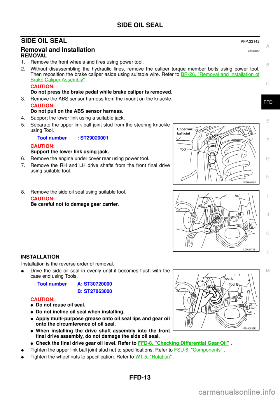
5. Separate the upper link ball joint stud from the steering knuckle
using Tool.
CAUTION:
Support the lower link using jack.
6. Remove the engine under cover rear using power tool.
7. Remove the RH and LH drive shafts from the front final drive
using suitable tool.
8. Remove the side oil seal using suitable tool.
CAUTION:
Be careful not to damage gear carrier.
INSTALLATION
Installation is the reverse order of removal.
lDrive the side oil seal in evenly until it becomes flush with the
case end using Tools.
CAUTION:
lDo not reuse oil seal.
lDo not incline oil seal when installing.
lApply multi-purpose grease onto oil seal lips and gear oil
onto the circumference of oil seal.
lWhen installing the drive shaft assembly into the front
final drive assembly, do not damage the side oil seal.
lCheck the final drive gear oil level. Refer toFFD-8, "Checking Differential Gear Oil".
lTighten the upper link ball joint stud nut to specifications. Refer toFSU-6, "Components".
lTighten the wheel nuts to specification. Refer toWT-5, "Rotation". Tool number : ST29020001
WEIA0119E
LDIA0173E
Tool number A: ST30720000
B: ST27863000
PDIA0826E
Page 1561 of 3171
FRONT FINAL DRIVE ASSEMBLY
FFD-15
C
E
F
G
H
I
J
K
L
MA
B
FFD
FRONT FINAL DRIVE ASSEMBLYPFP:38500
Removal and InstallationEDS00356
REMOVAL
1. Remove the front wheels and tires using power tool.
2. Without disassembling the hydraulic lines, remove the caliper torque member bolts using power tool.
Then reposition the brake caliper aside using suitable wire. Refer toBR-26, "
Removal and Installation of
Brake Caliper Assembly".
CAUTION:
Do not press the brake pedal while brake caliper is removed.
3. Remove the ABS sensor harness from the mount on the knuckle.
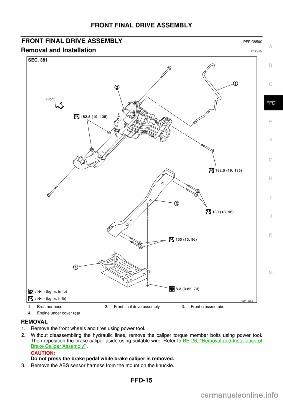
1. Breather hose 2. Front final drive assembly 3. Front crossmember
4. Engine under cover rear
PDIA1035E
Page 1607 of 3171
ON-VEHICLE SERVICE
FSU-7
C
D
F
G
H
I
J
K
L
MA
B
FSU
ON-VEHICLE SERVICEPFP:00000
Front Suspension PartsEES002KM
Check front suspension parts for excessive play, cracks, wear and
other damage.
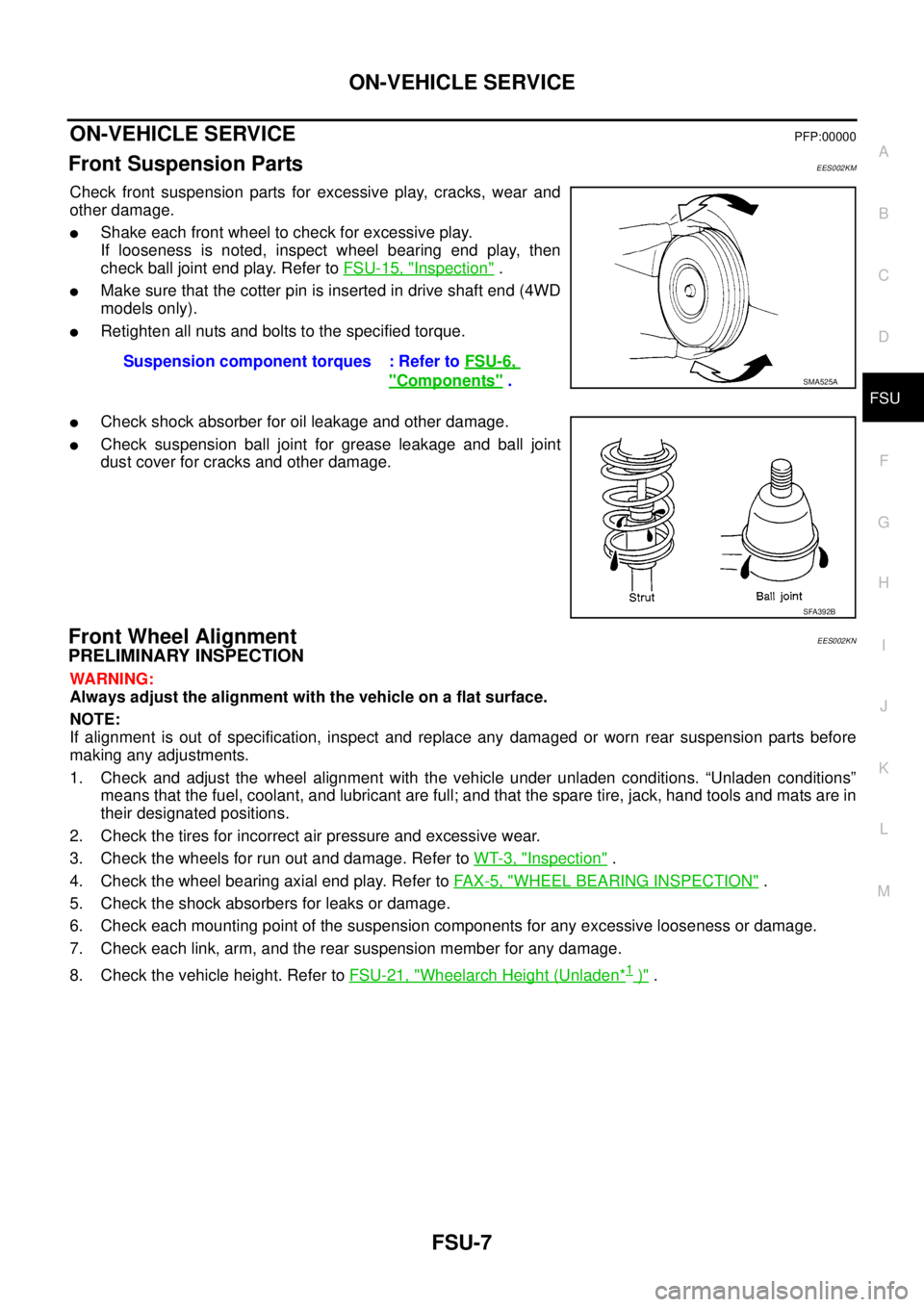
lShake each front wheel to check for excessive play.
If looseness is noted, inspect wheel bearing end play, then
check ball joint end play. Refer toFSU-15, "
Inspection".
lMake sure that the cotter pin is inserted in drive shaft end (4WD
models only).
lRetighten all nuts and bolts to the specified torque.
lCheck shock absorber for oil leakage and other damage.
lCheck suspension ball joint for grease leakage and ball joint
dust cover for cracks and other damage.
Front Wheel AlignmentEES002KN
PRELIMINARY INSPECTION
WARNING:
Always adjust the alignment with the vehicle on a flat surface.
NOTE:
If alignment is out of specification, inspect and replace any damaged or worn rear suspension parts before
making any adjustments.
1. Check and adjust the wheel alignment with the vehicle under unladen conditions. “Unladen conditions”
means that the fuel, coolant, and lubricant are full; and that the spare tire, jack, hand tools and mats are in
their designated positions.
2. Check the tires for incorrect air pressure and excessive wear.
3. Check the wheels for run out and damage. Refer toWT-3, "
Inspection".
4. Check the wheel bearing axial end play. Refer toFA X - 5 , "
WHEEL BEARING INSPECTION".
5. Check the shock absorbers for leaks or damage.
6. Check each mounting point of the suspension components for any excessive looseness or damage.
7. Check each link, arm, and the rear suspension member for any damage.
8. Check the vehicle height. Refer toFSU-21, "
Wheelarch Height (Unladen*1)". Suspension component torques : Refer toFSU-6,
"Components".SMA525A
SFA392B
Page 1618 of 3171
FSU-18
KNUCKLE
INSTALLATION
Installation is in the reverse order of removal.
lRefer toFSU-6, "Components"for tightening torques.
CAUTION:
Discard the old cotter pin; replace with a new one.
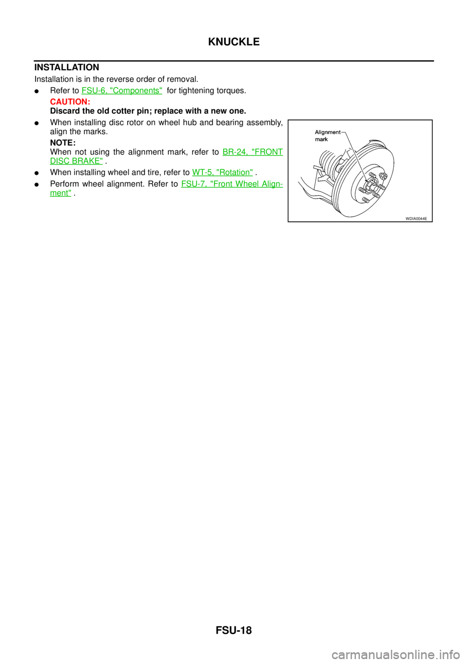
lWhen installing disc rotor on wheel hub and bearing assembly,
align the marks.
NOTE:
When not using the alignment mark, refer toBR-24, "
FRONT
DISC BRAKE".
lWhen installing wheel and tire, refer toWT-5, "Rotation".
lPerform wheel alignment. Refer toFSU-7, "Front Wheel Align-
ment".
WDIA0044E