2005 NISSAN NAVARA wheel torque
[x] Cancel search: wheel torquePage 1624 of 3171

GI-2
TIGHTENING TORQUE OF STANDARD BOLTS .... 55
Tightening Torque Table ......................................... 55
IDENTIFICATION INFORMATION ............................ 56
Model Variation ....................................................... 56
Identification Number .............................................. 57
VEHICLE IDENTIFICATION NUMBER
ARRANGEMENT ................................................. 57
IDENTIFICATION PLATE .................................... 58
ENGINE SERIAL NUMBER ................................ 58TRANSFER SERIAL NUMBER ........................... 58
AUTOMATIC TRANSMISSION NUMBER ........... 58
MANUAL TRANSMISSION NUMBER ................. 59
Dimensions ............................................................. 60
KING CAB ............................................................ 60
DOUBLE CAB ...................................................... 60
Wheels & Tyres ....................................................... 60
TERMINOLOGY ........................................................ 61
ISO 15031-2 Terminology List ................................. 61
Page 1759 of 3171
IDX-7
A
C
D
E
F
G
H
I
J
K
L B
IDX
ALPHABETICAL INDEX
Starter ................................................................SC-27
Starting system ..................................................SC-27
Steering gear, linkage and transfer gear inspection .....
MA-36
,MA-37
Steering linkage .................................................PS-14
Steering wheel and column .................................PS-8
Step lamp .........................................................LT-145
Stop lamp .........................................................LT-121
Stop lamp switch .............................................EC-330
STOP/L - Wiring diagram .................................LT-121
Striking rod (M/T) ...............................................MT-23
Strut (front) ......................................................FSU-10
Sun roof, electric ................................................RF-10
Sunload sensor ..............................................ATC-112
Sunroof ..................................................RF-10,RF-21
Super lock ...........................................................BL-55
Supplemental Restraint System ........................SRS-6
Symbols and abbreviations .....................GI-10,GI-23
Symptom matrix chart ........................................EC-42
Synchronizer (M/T) ............................................MT-21
T
Tachometer ..........................................................DI-4
Tail lamp ...........................................................LT-125
TAIL/L - Wiring diagram ....................................LT-127
TC boost control solnoid valve ........................EC-309
TC boost sensor ..............................................EC-153
TCC/V - Wiring diagram ..................................EC-311
TCM circuit diagram ..........................................AT-42
TCM inspection table .........................................AT-76
Thermostat ........................................................CO-24
Three way catalyst precautions ............................GI-5
Throttle body ......................................................EM-20
Tie-rod ...............................................................PS-14
Timing chain .........................................EM-73,EM-79
Timing gear ........................................................EM-79
Tire rotation .......................................................MA-34
Tire size ..............................................................GI-60
Torque converter installation ...........................AT-250
Torque convertor clutch solenoid valveAT-110,AT-112
Tow truck towing .................................................GI-53
Towing point .......................................................GI-54
Transfer control device .............TF-74,TF-78,TF-105
Transfer control unit inspection table ..................TF-38
Transfer oil replacement ....................................MA-32
Transfer serial number .......................................GI-58
Transmission case (M/T) ...................................MT-19
Transmission serial number ....................GI-58,GI-59
Tread-FR&RR (Dimensions) ..............................GI-60
Trim .....................................................................EI-33
Trouble diagnoses ..............................................GI-11
Turbine revolution sensor ................................AT-123
Turbocharger .....................................................EM-28
Turbocharger charge air cooler .........................EM-18
Turbocharger precautions ....................................GI-6
TURN - Wiring diagram ....................................LT-100
Turn signal lamp .................................................LT-97
Two-pole lift ........................................................GI-52
V
Vacuum hose drawing (Engine control) .............EC-16
Vacuum pump ...................................................EM-42
Valve clearance ................................................EM-66
Valve guide .....................................................EM-101
Valve lifter .........................................................EM-62
Valve seat .......................................................EM-103
Valve spring ....................................................EM-104
Vanity mirror lamp .............................................LT-145
Vehicle identification number ..............................GI-57
Vehicle recovery (freeing a stuck vehicle) ..........GI-54
VEHSEC - Wiring diagram ...............................BL-143
Viscosity number (SAE) ....................................MA-15
W
Wait detection switch ..............................TF-63
,TF-66
WARN - Wiring diagram .....................................DI-30
Warning chime ....................................................DI-51
Warning lamps ....................................................DI-28
Washer, front .....................................................WW-4
Water pump ......................................................CO-21
Water temperature gauge .....................................DI-4
Wheel alignment (front) .....................................FSU-7
Wheel balance ..................................................MA-34
Wheel bearing (front) .........................................FAX-5
Wheel bearing (rear) .........................................RAX-6
Wheel sensors (ABS) .....................................BRC-37
Wheel size ..........................................................GI-60
Wheelbase (Dimensions) ....................................GI-60
Width (Dimensions) ............................................GI-60
WINDOW - Wiring diagram ...............................GW-20
Window, door ......................................GW-35,GW-38
Window, rear .....................................................GW-43
Windshield ........................................................GW-11
WIPER - Wiring diagram ..................................WW-12
Wiper, front ........................................................WW-4
Wiring Diagram (Cell code) list ..........................PG-68
Wiring diagrams ..................................................GI-15
Page 2280 of 3171
DESCRIPTION
MA-5
C
D
E
F
G
H
I
J
K
MA
B
MA
DESCRIPTIONPFP:00000
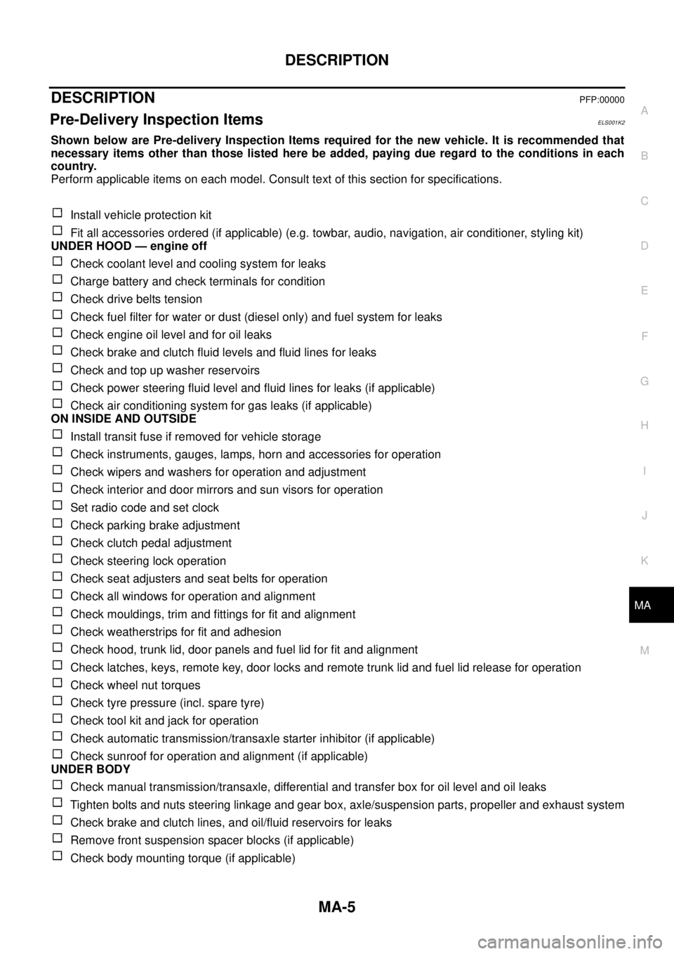
Pre-Delivery Inspection ItemsELS001K2
Shown below are Pre-delivery Inspection Items required for the new vehicle. It is recommended that
necessary items other than those listed here be added, paying due regard to the conditions in each
country.
Perform applicable items on each model. Consult text of this section for specifications.
Install vehicle protection kit
Fit all accessories ordered (if applicable) (e.g. towbar, audio, navigation, air conditioner, styling kit)
UNDER HOOD — engine off
Check coolant level and cooling system for leaks
Charge battery and check terminals for condition
Check drive belts tension
Check fuel filter for water or dust (diesel only) and fuel system for leaks
Check engine oil level and for oil leaks
Check brake and clutch fluid levels and fluid lines for leaks
Check and top up washer reservoirs
Check power steering fluid level and fluid lines for leaks (if applicable)
Check air conditioning system for gas leaks (if applicable)
ON INSIDE AND OUTSIDE
Install transit fuse if removed for vehicle storage
Check instruments, gauges, lamps, horn and accessories for operation
Check wipers and washers for operation and adjustment
Check interior and door mirrors and sun visors for operation
Set radio code and set clock
Check parking brake adjustment
Check clutch pedal adjustment
Check steering lock operation
Check seat adjusters and seat belts for operation
Check all windows for operation and alignment
Check mouldings, trim and fittings for fit and alignment
Check weatherstrips for fit and adhesion
Check hood, trunk lid, door panels and fuel lid for fit and alignment
Check latches, keys, remote key, door locks and remote trunk lid and fuel lid release for operation
Check wheel nut torques
Check tyre pressure (incl. spare tyre)
Check tool kit and jack for operation
Check automatic transmission/transaxle starter inhibitor (if applicable)
Check sunroof for operation and alignment (if applicable)
UNDER BODY
Check manual transmission/transaxle, differential and transfer box for oil level and oil leaks
Tighten bolts and nuts steering linkage and gear box, axle/suspension parts, propeller and exhaust system
Check brake and clutch lines, and oil/fluid reservoirs for leaks
Remove front suspension spacer blocks (if applicable)
Check body mounting torque (if applicable)
Page 2309 of 3171
MA-34
CHASSIS AND BODY MAINTENANCE
Changing Rear Final Drive Oil (Rear Differential Gear Oil)
ELS001IW
CAUTION:
If using the vehicle for towing, the final drive oil must be replaced as specified. Refer toMA-8, "
PERI-
ODIC MAINTENANCE".
DRAINING
1. Stop the engine.
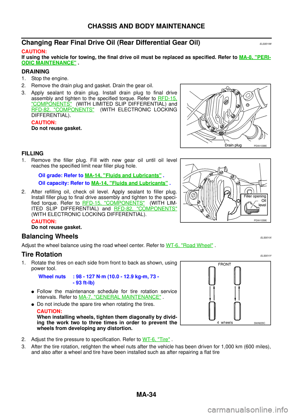
2. Remove the drain plug and gasket. Drain the gear oil.
3. Apply sealant to drain plug. Install drain plug to final drive
assembly and tighten to the specified torque. Refer toRFD-15,
"COMPONENTS"(WITH LIMITED SLIP DIFFERENTIAL) and
RFD-82, "
COMPONENTS"(WITH ELECTRONIC LOCKING
DIFFERENTIAL).
CAUTION:
Do not reuse gasket.
FILLING
1. Remove the filler plug. Fill with new gear oil until oil level
reaches the specified limit near filler plug hole.
2. After refilling oil, check oil level. Apply sealant to filler plug.
Install filler plug to final drive assembly and tighten to the speci-
fied torque. Refer toRFD-15, "
COMPONENTS"(WITH LIM-
ITED SLIP DIFFERENTIAL) andRFD-82, "
COMPONENTS"
(WITH ELECTRONIC LOCKING DIFFERENTIAL).
CAUTION:
Do not reuse gasket.
Balancing WheelsELS001IX
Adjust the wheel balance using the road wheel center. Refer toWT-6, "Road Wheel".
Tire RotationELS001IY
1. Rotate the tires on each side from front to back as shown, using
power tool.
lFollow the maintenance schedule for tire rotation service
intervals. Refer toMA-7, "
GENERAL MAINTENANCE".
lDo not include the spare tire when rotating the tires.
CAUTION:
When installing wheels, tighten them diagonally by divid-
ing the work two to three times in order to prevent the
wheels from developing any distortion.
2. Adjust the tire pressure to specification. Refer toWT-6, "
Tire".
3. After the tire rotation, retighten the wheel nuts after the vehicle has been driven for 1,000 km (600 miles),
and also after a wheel and tire have been installed such as after repairing a flat tire
PDIA1038E
Oil grade: Refer toMA-14, "Fluids and Lubricants".
Oil capacity: Refer toMA-14, "
Fluids and Lubricants".
PDIA1039E
Wheel nuts : 98 - 127 N·m (10.0 - 12.9 kg-m, 73 -
- 93 ft-lb)
SMA829C
Page 2335 of 3171
MT-18
TRANSMISSION ASSEMBLY
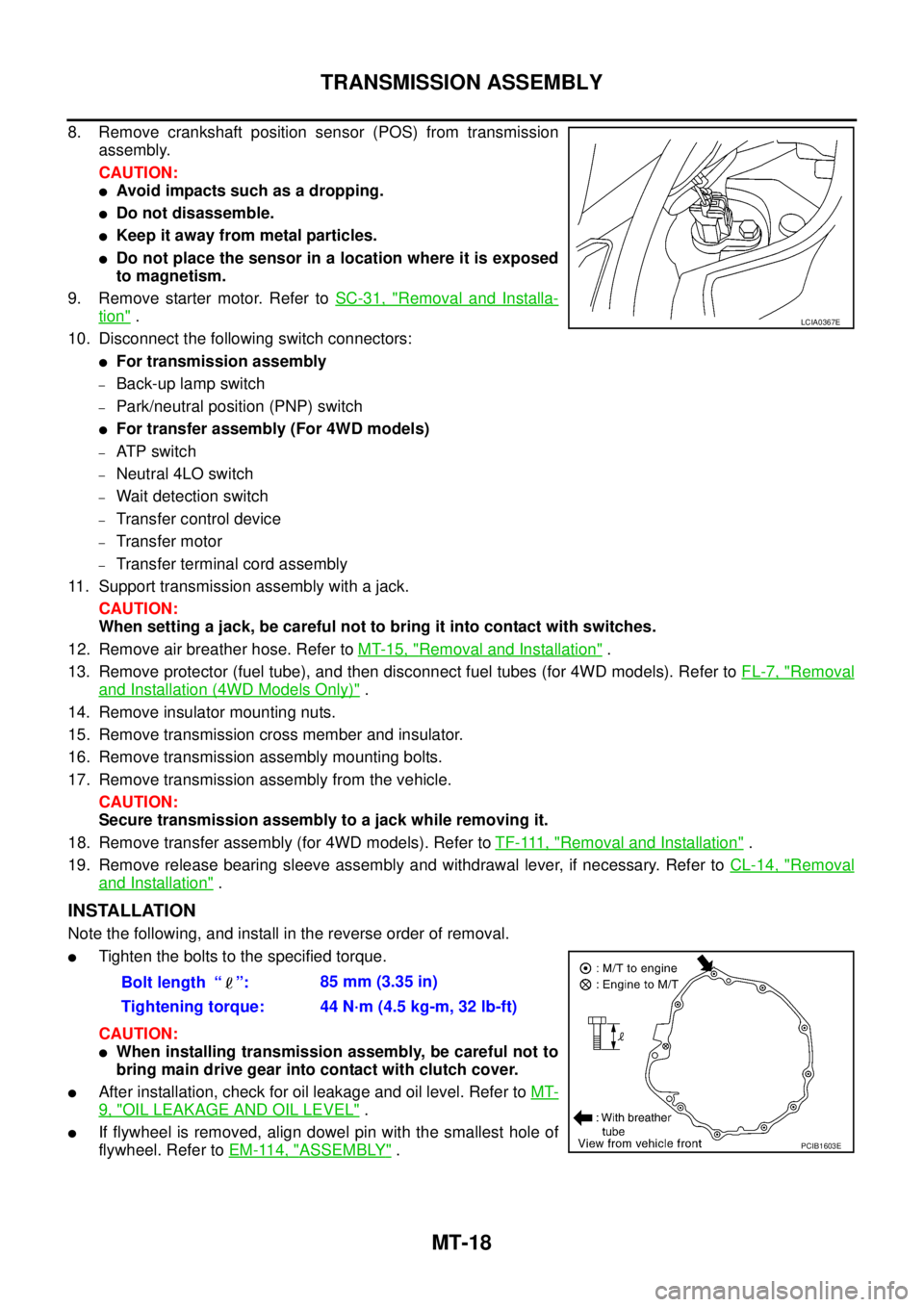
8. Remove crankshaft position sensor (POS) from transmission
assembly.
CAUTION:
lAvoid impacts such as a dropping.
lDo not disassemble.
lKeep it away from metal particles.
lDo not place the sensor in a location where it is exposed
to magnetism.
9. Remove starter motor. Refer toSC-31, "
Removal and Installa-
tion".
10. Disconnect the following switch connectors:
lFor transmission assembly
–Back-up lamp switch
–Park/neutral position (PNP) switch
lFor transfer assembly (For 4WD models)
–AT P s w i t c h
–Neutral 4LO switch
–Wait detection switch
–Transfer control device
–Transfer motor
–Transfer terminal cord assembly
11. Support transmission assembly with a jack.
CAUTION:
When setting a jack, be careful not to bring it into contact with switches.
12. Remove air breather hose. Refer toMT-15, "
Removal and Installation".
13. Remove protector (fuel tube), and then disconnect fuel tubes (for 4WD models). Refer toFL-7, "
Removal
and Installation (4WD Models Only)".
14. Remove insulator mounting nuts.
15. Remove transmission cross member and insulator.
16. Remove transmission assembly mounting bolts.
17. Remove transmission assembly from the vehicle.
CAUTION:
Secure transmission assembly to a jack while removing it.
18. Remove transfer assembly (for 4WD models). Refer toTF-111, "
Removal and Installation".
19. Remove release bearing sleeve assembly and withdrawal lever, if necessary. Refer toCL-14, "
Removal
and Installation".
INSTALLATION
Note the following, and install in the reverse order of removal.
lTighten the bolts to the specified torque.
CAUTION:
lWhen installing transmission assembly, be careful not to
bring main drive gear into contact with clutch cover.
lAfter installation, check for oil leakage and oil level. Refer toMT-
9, "OIL LEAKAGE AND OIL LEVEL".
lIf flywheel is removed, align dowel pin with the smallest hole of
flywheel. Refer toEM-114, "
ASSEMBLY".
LCIA0367E
Bolt length “ ”:85 mm (3.35 in)
Tightening torque: 44 N·m (4.5 kg-m, 32 lb-ft)
PCIB1603E
Page 2513 of 3171
MTC-126
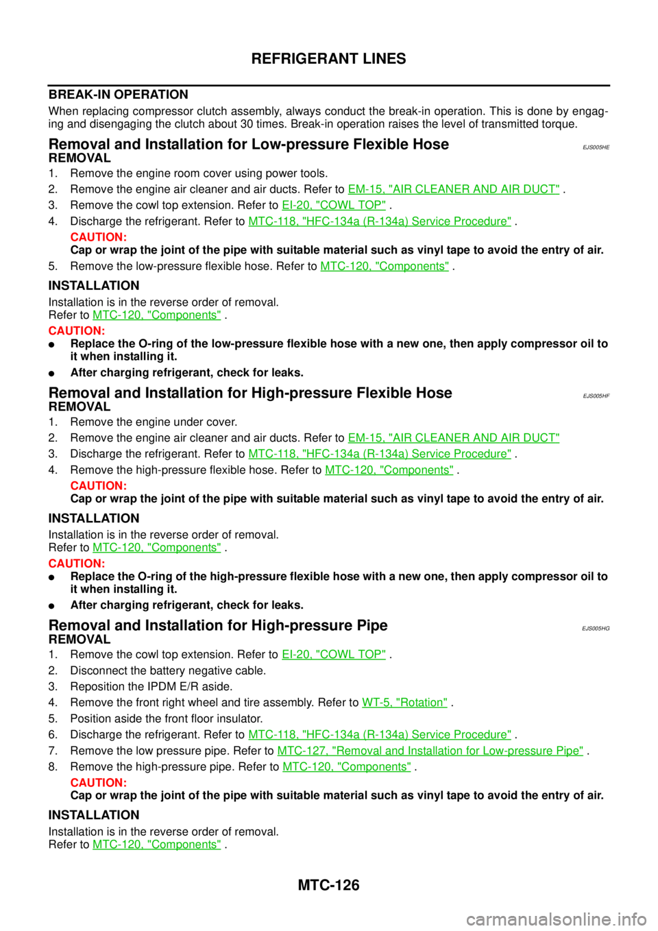
REFRIGERANT LINES
BREAK-IN OPERATION
When replacing compressor clutch assembly, always conduct the break-in operation. This is done by engag-
ing and disengaging the clutch about 30 times. Break-in operation raises the level of transmitted torque.
Removal and Installation for Low-pressure Flexible HoseEJS005HE
REMOVAL
1. Remove the engine room cover using power tools.
2. Remove the engine air cleaner and air ducts. Refer toEM-15, "
AIR CLEANER AND AIR DUCT".
3. Remove the cowl top extension. Refer toEI-20, "
COWL TOP".
4. Discharge the refrigerant. Refer toMTC-118, "
HFC-134a (R-134a) Service Procedure".
CAUTION:
Cap or wrap the joint of the pipe with suitable material such as vinyl tape to avoid the entry of air.
5. Remove the low-pressure flexible hose. Refer toMTC-120, "
Components".
INSTALLATION
Installation is in the reverse order of removal.
Refer toMTC-120, "
Components".
CAUTION:
lReplace the O-ring of the low-pressure flexible hose with a new one, then apply compressor oil to
it when installing it.
lAfter charging refrigerant, check for leaks.
Removal and Installation for High-pressure Flexible HoseEJS005HF
REMOVAL
1. Remove the engine under cover.
2. Remove the engine air cleaner and air ducts. Refer toEM-15, "
AIR CLEANER AND AIR DUCT"
3. Discharge the refrigerant. Refer toMTC-118, "HFC-134a (R-134a) Service Procedure".
4. Remove the high-pressure flexible hose. Refer toMTC-120, "
Components".
CAUTION:
Cap or wrap the joint of the pipe with suitable material such as vinyl tape to avoid the entry of air.
INSTALLATION
Installation is in the reverse order of removal.
Refer toMTC-120, "
Components".
CAUTION:
lReplace the O-ring of the high-pressure flexible hose with a new one, then apply compressor oil to
it when installing it.
lAfter charging refrigerant, check for leaks.
Removal and Installation for High-pressure PipeEJS005HG
REMOVAL
1. Remove the cowl top extension. Refer toEI-20, "COWL TOP".
2. Disconnect the battery negative cable.
3. Reposition the IPDM E/R aside.
4. Remove the front right wheel and tire assembly. Refer toWT-5, "
Rotation".
5. Position aside the front floor insulator.
6. Discharge the refrigerant. Refer toMTC-118, "
HFC-134a (R-134a) Service Procedure".
7. Remove the low pressure pipe. Refer toMTC-127, "
Removal and Installation for Low-pressure Pipe".
8. Remove the high-pressure pipe. Refer toMTC-120, "
Components".
CAUTION:
Cap or wrap the joint of the pipe with suitable material such as vinyl tape to avoid the entry of air.
INSTALLATION
Installation is in the reverse order of removal.
Refer toMTC-120, "
Components".
Page 2617 of 3171
PR-2
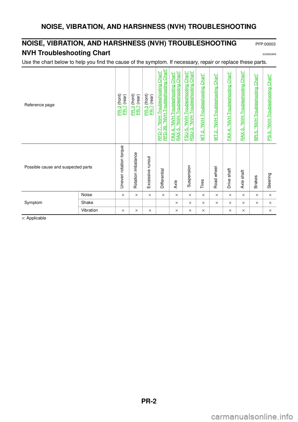
NOISE, VIBRATION, AND HARSHNESS (NVH) TROUBLESHOOTING
NOISE, VIBRATION, AND HARSHNESS (NVH) TROUBLESHOOTING
PFP:00003
NVH Troubleshooting ChartEDS002WN
Use the chart below to help you find the cause of the symptom. If necessary, repair or replace these parts.
´: ApplicableReference page
PR-3
(front)
PR-7(rear)
PR-3(front)
PR-7(rear)
PR-3(front)
PR-7(rear)
RFD-7, "
NVH Troubleshooting Chart
"
RFD-39, "
NVH Troubleshooting Chart
"
FA X -4 , "
NVH Troubleshooting Chart
"
RAX-5, "
NVH Troubleshooting Chart
"
FSU-5, "
NVH Troubleshooting Chart
"
RSU-3, "
NVH Troubleshooting Chart
"
WT-2, "
NVH Troubleshooting Chart
"
WT-2, "
NVH Troubleshooting Chart
"
FA X -4 , "
NVH Troubleshooting Chart
"
RAX-5, "
NVH Troubleshooting Chart
"
BR-5, "
NVH Troubleshooting Chart
"
PS-5, "
NVH Troubleshooting Chart
"
Possible cause and suspected parts
Uneven rotation torque
Rotation imbalance
Excessive runout
Differential
Axle
Suspension
Tires
Road wheel
Drive shaft
Axle shaft
Brakes
Steering
SymptomNoise´´´´´´´´´´´´
Shake´´´´´´´´
Vibration´´´ ´´´ ´´ ´
Page 2630 of 3171
![NISSAN NAVARA 2005 Repair Workshop Manual PREPARATION
PS-3
C
D
E
F
H
I
J
K
L
MA
B
PS
PREPARATIONPFP:00002
Special Service Tools [SST]EGS001LA
Tool number
Tool nameDescription
ST27180001
Steering wheel pullerRemoving steering wheel
ST3127 S000 NISSAN NAVARA 2005 Repair Workshop Manual PREPARATION
PS-3
C
D
E
F
H
I
J
K
L
MA
B
PS
PREPARATIONPFP:00002
Special Service Tools [SST]EGS001LA
Tool number
Tool nameDescription
ST27180001
Steering wheel pullerRemoving steering wheel
ST3127 S000](/manual-img/5/57362/w960_57362-2629.png)
PREPARATION
PS-3
C
D
E
F
H
I
J
K
L
MA
B
PS
PREPARATIONPFP:00002
Special Service Tools [SST]EGS001LA
Tool number
Tool nameDescription
ST27180001
Steering wheel pullerRemoving steering wheel
ST3127 S000
Preload gauge
1. GG9103000
Torque wrench
2. HT62940000
Socket adapter
3. HT62900000
Socket adapterInspecting of rotating torque for ball joint
KV489Q0030
Rear cover wrench
a: 19 mm (0.75 in)
b: 34.9 mm (1.374 in)Removing and installing rear cover
KV489Q0020
Teflon ring correcting tool
a: 50 mm (1.97 in) dia.
b: 36 mm (1.42 in) dia.
c: 100 mm (3.94 in) dia.Installing rack Teflon ring
KV48103400
Preload adapterInspecting rotating torque
KV48103500
Pressure gaugeMeasuring oil pump relief pressure
KV48102500
Pressure gauge adapterMeasuring oil pump relief pressure
S-NT544
S-NT541
SGIA0516E
S-NT550
ZZA0824D
S-NT547
S-NT542