Page 2632 of 3171
NOISE, VIBRATION, AND HARSHNESS (NVH) TROUBLESHOOTING
PS-5
C
D
E
F
H
I
J
K
L
MA
B
PS
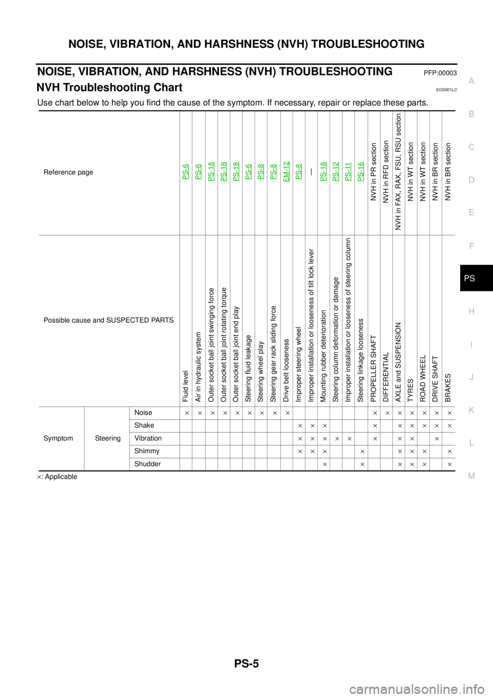
NOISE, VIBRATION, AND HARSHNESS (NVH) TROUBLESHOOTINGPFP:00003
NVH Troubleshooting ChartEGS001LC
Use chart below to help you find the cause of the symptom. If necessary, repair or replace these parts.
´: ApplicableReference page
PS-6PS-6PS-18PS-18PS-18PS-6PS-8PS-8EM-12PS-8—
PS-18PS-12PS-11PS-16
NVHinPRsection
NVH in RFD section
NVH in FAX, RAX, FSU, RSU section
NVH in WT section
NVH in WT section
NVHinBRsection
NVHinBRsection
Possible cause and SUSPECTED PARTS
Fluid level
Air in hydraulic system
Outer socket ball joint swinging force
Outer socket ball joint rotating torque
Outer socket ball joint end play
Steering fluid leakage
Steering wheel play
Steering gear rack sliding force
Drive belt looseness
Improper steering wheel
Improper installation or looseness of tilt lock lever
Mounting rubber deterioration
Steering column deformation or damage
Improper installation or looseness of steering column
Steering linkage looseness
PROPELLER SHAFT
DIFFERENTIAL
AXLE and SUSPENSION
TYRES
ROAD WHEEL
DRIVE SHAFT
BRAKES
Symptom SteeringNoise´ ´ ´´´´´ ´ ´ ´´´´´´ ´
Shake´´´ ´ ´´´´ ´
Vibration´´´´´ ´ ´´ ´
Shimmy´´´ ´ ´´´ ´
Shudder´ ´ ´´´ ´
Page 2642 of 3171
POWER STEERING GEAR AND LINKAGE
PS-15
C
D
E
F
H
I
J
K
L
MA
B
PS
7. Remove high and low pressure piping of hydraulic piping, and
then drain power steering fluid. Refer toPS-6, "
POWER
STEERING FLUID".
8. Remove steering hydraulic piping bracket from front suspension
member. Refer toPS-30, "
HYDRAULIC LINE".
9. Remove mounting bolts and nuts of steering gear assembly, and
then remove steering gear assembly, rack mounting bracket,
rack mounting insulator and washer from vehicle.
INSTALLATION
lInstallation is the reverse order of removal. For tightening torque, refer toPS-14, "COMPONENT".
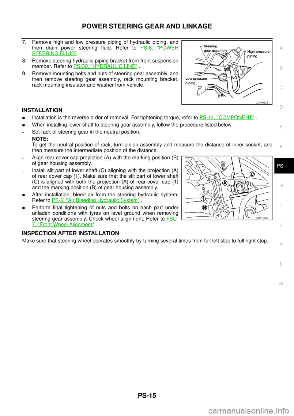
lWhen installing lower shaft to steering gear assembly, follow the procedure listed below.
–Set rack of steering gear in the neutral position.
NOTE:
To get the neutral position of rack, turn pinion assembly and measure the distance of inner socket, and
then measure the intermediate position of the distance.
–Align rear cover cap projection (A) with the marking position (B)
of gear housing assembly.
–Install slit part of lower shaft (C) aligning with the projection (A)
of rear cover cap (1). Make sure that the slit part of lower shaft
(C) is aligned with both the projection (A) of rear cover cap (1)
and the marking position (B) of gear housing assembly.
lAfter installation, bleed air from the steering hydraulic system.
Refer toPS-6, "
Air Bleeding Hydraulic System".
lPerform final tightening of nuts and bolts on each part under
unladen conditions with tyres on level ground when removing
steering gear assembly. Check wheel alignment. Refer toFSU-
7, "Front Wheel Alignment".
INSPECTION AFTER INSTALLATION
Make sure that steering wheel operates smoothly by turning several times from full left stop to full right stop.
LGIA0032E
SGIA1140E
Page 2661 of 3171
PS-34
SERVICE DATA AND SPECIFICATIONS (SDS)
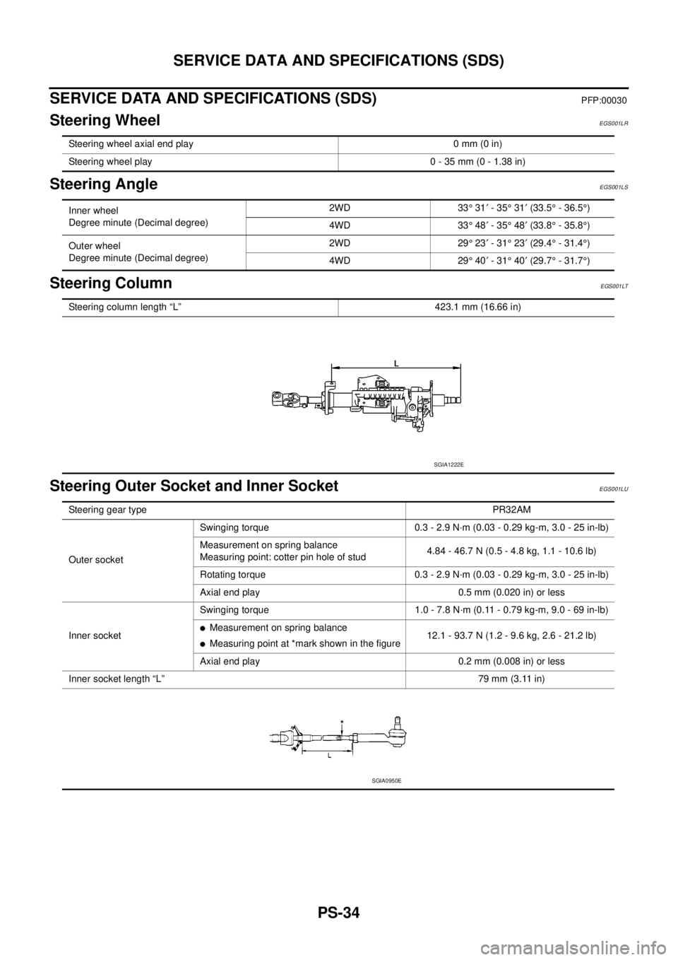
SERVICE DATA AND SPECIFICATIONS (SDS)
PFP:00030
Steering WheelEGS001LR
Steering AngleEGS001LS
Steering ColumnEGS001LT
Steering Outer Socket and Inner SocketEGS001LU
Steering wheel axial end play 0 mm (0 in)
Steering wheel play 0 - 35 mm (0 - 1.38 in)
Inner wheel
Degree minute (Decimal degree)2WD 33°31¢-35°31¢(33.5°- 36.5°)
4WD 33°48¢-35°48¢(33.8°- 35.8°)
Outer wheel
Degree minute (Decimal degree)2WD 29°23¢-31°23¢(29.4°- 31.4°)
4WD 29°40¢-31°40¢(29.7°- 31.7°)
Steering column length “L” 423.1 mm (16.66 in)
SGIA1222E
Steering gear typePR32AM
Outer socketSwinging torque 0.3 - 2.9 N·m (0.03 - 0.29 kg-m, 3.0 - 25 in-lb)
Measurement on spring balance
Measuring point: cotter pin hole of stud4.84 - 46.7 N (0.5 - 4.8 kg, 1.1 - 10.6 lb)
Rotating torque 0.3 - 2.9 N·m (0.03 - 0.29 kg-m, 3.0 - 25 in-lb)
Axial end play 0.5 mm (0.020 in) or less
Inner socketSwinging torque 1.0 - 7.8 N·m (0.11 - 0.79 kg-m, 9.0 - 69 in-lb)
lMeasurement on spring balance
lMeasuring point at *mark shown in the figure12.1 - 93.7 N (1.2 - 9.6 kg, 2.6 - 21.2 lb)
Axial end play 0.2 mm (0.008 in) or less
Inner socket length “L”79 mm (3.11 in)
SGIA0950E
Page 2669 of 3171
RAX-6
[M226]
ON-VEHICLE SERVICE
ON-VEHICLE SERVICE
PFP:00000
Rear Axle PartsEDS003HX
lCheck the axle parts for excessive play, wear, and damage. Replace as necessary.
lShake each rear wheel to check for excessive play. Repair as
necessary
lRetighten all nuts and bolts to the specified torque. Refer to
RAX-7, "
AXLE SHAFT".
Rear Axle BearingEDS003HY
lCheck that the axle shaft bearing operates smoothly. Replace as necessary.
SMA525A
Page 2672 of 3171
![NISSAN NAVARA 2005 Repair Workshop Manual AXLE SHAFT
RAX-9
[M226]
C
E
F
G
H
I
J
K
L
MA
B
RAX
INSPECTION AFTER REMOVAL
Axle Shaft Bearing and Cup
lCheck that the axle shaft bearing and cup roll freely and are free from noise, cracks, pitting a NISSAN NAVARA 2005 Repair Workshop Manual AXLE SHAFT
RAX-9
[M226]
C
E
F
G
H
I
J
K
L
MA
B
RAX
INSPECTION AFTER REMOVAL
Axle Shaft Bearing and Cup
lCheck that the axle shaft bearing and cup roll freely and are free from noise, cracks, pitting a](/manual-img/5/57362/w960_57362-2671.png)
AXLE SHAFT
RAX-9
[M226]
C
E
F
G
H
I
J
K
L
MA
B
RAX
INSPECTION AFTER REMOVAL
Axle Shaft Bearing and Cup
lCheck that the axle shaft bearing and cup roll freely and are free from noise, cracks, pitting and wear.
Replace if necessary.
Axle Shaft Retainer
lCheck for deformation and cracks. Replace if necessary.
Rear Axle Case
lCheck the exterior and inner machined surfaces for deformation and cracks. Replace if necessary.
INSTALLATION
Installation is in the reverse order of removal.
When installing pay attention to following points:
lInstall a new shaft guide and a new oil seal into the rear axle case.
CAUTION:
lDo not reuse the axle oil seal. The axle oil seal must be replaced every time the axle shaft assem-
bly is removed from the axle shaft housing.
lWhen installing oil seals, apply multi-purpsose grease to oil seal lips.
lInstall four new lock nuts to secure the axle shaft assembly to the rear axle case, and tighten lock nuts to
the specified torque. Refer toRAX-7, "
Removal and Installation".
lReinstall the rear brake drum. Refer toBR-31, "Removal and Installation of Drum Brake Assembly".
lAdjust the differential gear oil level.
Refer toRFD-9, "
DIFFERENTIAL GEAR OIL", for M226 without LD.
Refer toRFD-9, "
DIFFERENTIAL GEAR OIL", for M226 with LD.
lReinstall the wheel. Refer toWT-5, "Rotation".
DISASSEMBLY
1. Remove the ABS sensor rotor. Refer toBRC-39, "SENSOR ROTOR".
2. Remove the snap ring from the axle shaft using a suitable snap ring pliers.
3. Secure the axle shaft in a suitable vise as shown, and use a
brass hammer to remove studs (4) from the axle shaft retainer.
CAUTION:
lMount the axle shaft using a soft jaw vise to avoid dam-
aging the axle shaft retainer.
MDIB9051E
Page 2810 of 3171
REAR SUSPENSION ASSEMBLY
RSU-5
C
D
F
G
H
I
J
K
L
MA
B
RSU
CAUTION:
When installing the components with rubber bushings, the final tightening of the nuts and bolts must
be done with the vehicle in an unladen condition (the fuel, engine coolant, and engine oil full; the
spare tire, jack, hand tools and mats in their designated positions) with the tires on the ground.
On-Vehicle Inspection and ServiceEES002JH
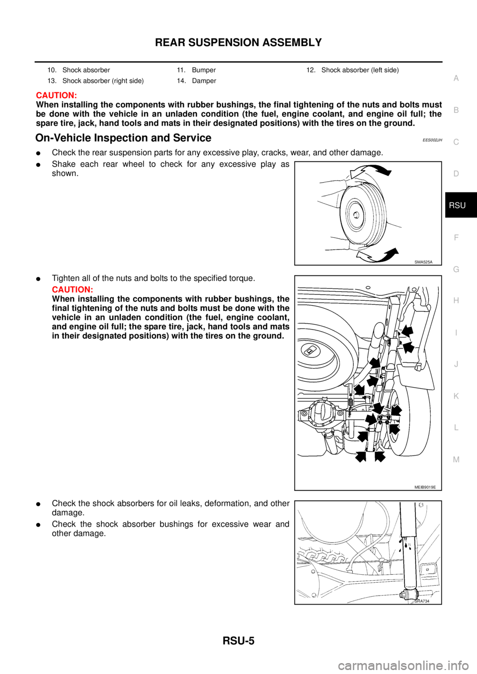
lCheck the rear suspension parts for any excessive play, cracks, wear, and other damage.
lShake each rear wheel to check for any excessive play as
shown.
lTighten all of the nuts and bolts to the specified torque.
CAUTION:
When installing the components with rubber bushings, the
final tightening of the nuts and bolts must be done with the
vehicle in an unladen condition (the fuel, engine coolant,
and engine oil full; the spare tire, jack, hand tools and mats
in their designated positions) with the tires on the ground.
lCheck the shock absorbers for oil leaks, deformation, and other
damage.
lCheck the shock absorber bushings for excessive wear and
other damage.
10. Shock absorber 11. Bumper 12. Shock absorber (left side)
13. Shock absorber (right side) 14. Damper
SMA525A
MEIB9019E
SRA734
Page 3110 of 3171
WHEEL AND TIRE ASSEMBLY
WT-5
C
D
F
G
H
I
J
K
L
MA
B
WT
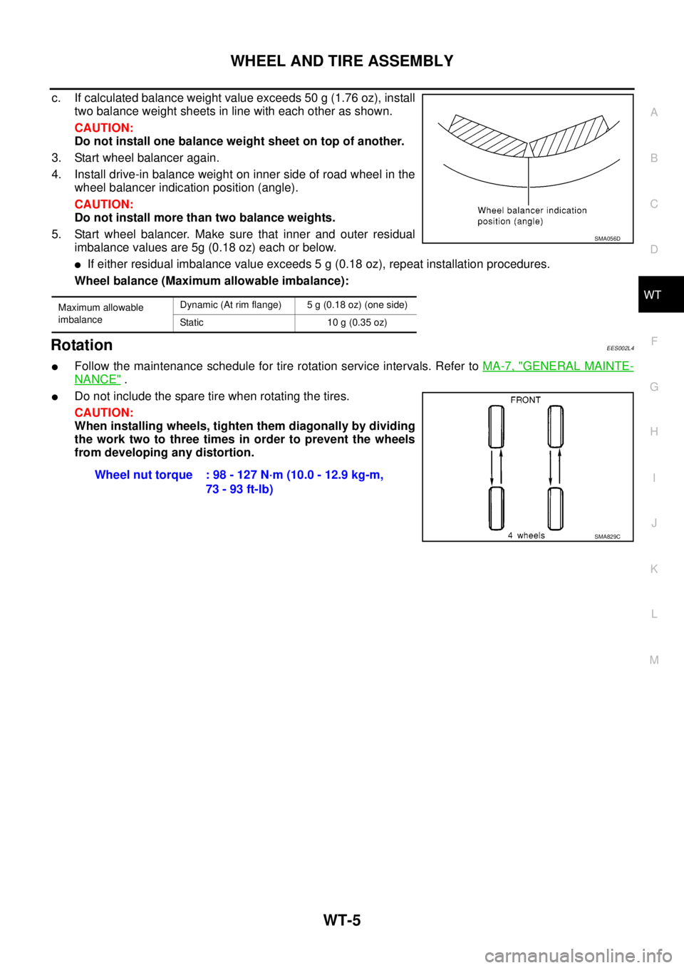
c. If calculated balance weight value exceeds 50 g (1.76 oz), install
two balance weight sheets in line with each other as shown.
CAUTION:
Do not install one balance weight sheet on top of another.
3. Start wheel balancer again.
4. Install drive-in balance weight on inner side of road wheel in the
wheel balancer indication position (angle).
CAUTION:
Do not install more than two balance weights.
5. Start wheel balancer. Make sure that inner and outer residual
imbalance values are 5g (0.18 oz) each or below.
lIf either residual imbalance value exceeds 5 g (0.18 oz), repeat installation procedures.
Wheel balance (Maximum allowable imbalance):
RotationEES002L4
lFollow the maintenance schedule for tire rotation service intervals. Refer toMA-7, "GENERAL MAINTE-
NANCE".
lDo not include the spare tire when rotating the tires.
CAUTION:
When installing wheels, tighten them diagonally by dividing
the work two to three times in order to prevent the wheels
from developing any distortion.
Maximum allowable
imbalanceDynamic (At rim flange) 5 g (0.18 oz) (one side)
Static 10 g (0.35 oz)
SMA056D
Wheel nut torque : 98 - 127 N·m (10.0 - 12.9 kg-m,
73 - 93 ft-lb)
SMA829C