2005 NISSAN NAVARA wheel size
[x] Cancel search: wheel sizePage 1682 of 3171

GI-60
IDENTIFICATION INFORMATION
Dimensions
EAS001DO
KING CAB
Unit: mm (in)
DOUBLE CAB
Unit: mm (in)
Wheels & TyresEAS001DP
Drive Type 2WD 4WD
Tyre size 235/70R16 255/70R16 235/70R16 255/70R16 265/70R16 255/65R17
Overall length 5220 (205.5)
Overall width 1850 (72.8)
Overall height 1743 (68.6) 1756 (69.1) 1751 (68.9) 1766 (69.5) 1777 (70.0) 1771 (69.7)
Front tread width
1570 (61.8)
Rear tread width
Wheelbase 3200 (126.0)
Drive Type 2WD 4WD
Tyre size 255/70R16 255/65R17 235/70R16 255/70R16 265/70R16 255/65R17
Overall length 5220 (205.5)
Overall width 1850 (72.8)
Overall height
(with Roof Rack)1881 (74.1) 1885 (74.2) 1873 (73.7) 1888 (74.3) 1899 (74.8) 1893 (74.5)
Overall height
(without Roof Rack)1771 (69.7) 1775 (69.9) 1764 (69.4) 1779 (70.0) 1789 (70.4) 1784 (70.2)
Front tread width
1570 (61.8)
Rear tread width
Wheelbase 3200 (126.0)
Drive Type Road wheel Tyre Spare tyre size
All16 X 7J Steel 235/70R16 235/70R16
16 X 7J Aluminum Alloy235/70R16 235/70R16
255/70R16 255/70R16
17 X 7J Aluminum Alloy 255/65R17 255/65R17
Page 1758 of 3171
IDX-6
ALPHABETICAL INDEX
P
P/SCKT - Wiring diagram ................................WW-57
Park/Neutral position switch ............................EC-342
Park/neutral position switch (A/T) ......................AT-99
Park/neutral position switch (M/T) ........MT-12,MT-19
Parking brake control ...........................................PB-2
Personal lamp ...................................................LT-145
Pilot bushing replacement ..............................EM-111
Piston pin inspection .......................................EM-125
Piston ring inspection ......................................EM-126
Piston to bore clearance .................................EM-129
Planetary carrier (Transfer) ..............................TF-129
PNP/SW - Wiring diagram ...............................EC-343
POWER - Wiring diagram ....................................PG-5
Power seat .........................................................SE-10
Power steering fluid level ..................................MA-37
Power steering gear ...........................................PS-14
Power steering oil pump ....................................PS-25
Power steering system bleeding ..........................PS-6
Power supply routing ...........................................PG-4
Power window ...................................................GW-15
Precations for Leak detection dye ....ATC-14,MTC-14
Precautions (General) ...........................................GI-4
Pre-delivery inspection .......................................MA-5
Pressure plate - See Clutch cover .....................CL-17
Pressure switch 1 ..............................AT-139,AT-156
Pressure switch 2 ............................................AT-154
Pressure switch 3 ..............................AT-134,AT-158
Pressure switch 5 ..............................AT-144,AT-160
Pressure switch 6 ..............................AT-149,AT-162
Pressure test (A/T) .............................................AT-44
Priming pump .....................................................EC-23
Propeller shaft ............................................PR-3,PR-7
Propeller shaft inspection .................................MA-32
Propeller shaft on vehicle service ........................PR-7
Propeller shaft vibration .............................PR-3,PR-7
Q
Quick-glow system ...........................................EC-295
R
R/FOG - Wiring diagram .....................................LT-89
Radiator ................................................CO-11,CO-15
Rear bumper .......................................................EI-17
Rear case (Transfer) ...........................TF-114,TF-120
Rear combination lamp removal and installation ..........
LT-144
Rear cover packing replacement diff. ..............FFD-14
Rear door ..........................................................GW-38
Rear seat ...........................................................SE-29
Rear seat belt ............................................SB-7,SB-9
Rear window .....................................................GW-43
Rear window defogger ......................................GW-47
Refrigerant connection precaution ........ATC-5,MTC-5
Refrigerant discharging evacuating chargingATC-138,
MTC-118
Refrigerant general precaution ............ATC-5,MTC-5
Refrigerant lines ...........ATC-138,ATC-146,ATC-147,
MTC-118
,MTC-126,MTC-127
Refrigerant pressure sensor ............EC-325,ATC-92,
ATC-147
,MTC-85,MTC-127
Refrigeration cycle ...........................ATC-20,MTC-20
Relay box ..........................................................PG-85
Removal and installation (A/T) .........................AT-247
Removal and installation (Transfer) .................TF-111
Reverse idler shaft (M/T) ..................................MT-21
Reverse lamp switch (M/T) - See Back-up lamp switch
(M/T) .....................................................MT-12
,MT-19
Reverse main gear (M/T) ..................................MT-21
Revolution sensor (A/T) .....................AT-103,AT-238
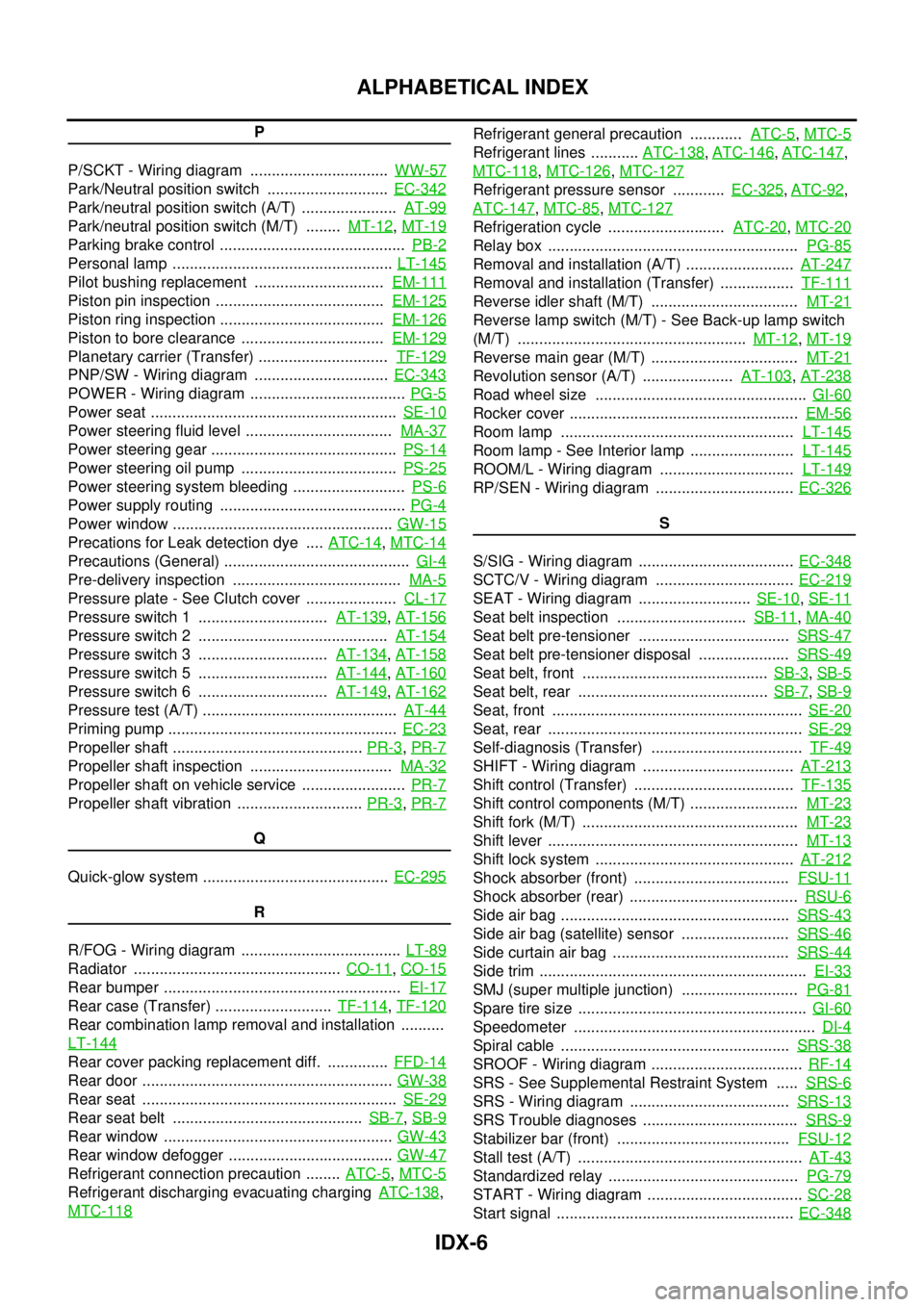
Road wheel size .................................................GI-60
Rocker cover .....................................................EM-56
Room lamp ......................................................LT-145
Room lamp - See Interior lamp ........................LT-145
ROOM/L - Wiring diagram ...............................LT-149
RP/SEN - Wiring diagram ................................EC-326
S
S/SIG - Wiring diagram ....................................EC-348
SCTC/V - Wiring diagram ................................EC-219
SEAT - Wiring diagram ..........................SE-10,SE-11
Seat belt inspection ..............................SB-11,MA-40
Seat belt pre-tensioner ...................................SRS-47
Seat belt pre-tensioner disposal .....................SRS-49
Seat belt, front ...........................................SB-3,SB-5
Seat belt, rear ............................................SB-7,SB-9
Seat, front ..........................................................SE-20
Seat, rear ...........................................................SE-29
Self-diagnosis (Transfer) ...................................TF-49
SHIFT - Wiring diagram ...................................AT-213
Shift control (Transfer) .....................................TF-135
Shift control components (M/T) .........................MT-23
Shift fork (M/T) ..................................................MT-23
Shift lever ..........................................................MT-13
Shift lock system ..............................................AT-212
Shock absorber (front) ....................................FSU-11
Shock absorber (rear) .......................................RSU-6
Side air bag .....................................................SRS-43
Side air bag (satellite) sensor .........................SRS-46
Side curtain air bag .........................................SRS-44
Side trim ..............................................................EI-33
SMJ (super multiple junction) ...........................PG-81
Spare tire size .....................................................GI-60
Speedometer ........................................................DI-4
Spiral cable .....................................................SRS-38
SROOF - Wiring diagram ...................................RF-14
SRS - See Supplemental Restraint System .....SRS-6
SRS - Wiring diagram .....................................SRS-13
SRS Trouble diagnoses ....................................SRS-9
Stabilizer bar (front) ........................................FSU-12
Stall test (A/T) ....................................................AT-43
Standardized relay ............................................PG-79
START - Wiring diagram ....................................SC-28
Start signal .......................................................EC-348
Page 1759 of 3171
IDX-7
A
C
D
E
F
G
H
I
J
K
L B
IDX
ALPHABETICAL INDEX
Starter ................................................................SC-27
Starting system ..................................................SC-27
Steering gear, linkage and transfer gear inspection .....
MA-36
,MA-37
Steering linkage .................................................PS-14
Steering wheel and column .................................PS-8
Step lamp .........................................................LT-145
Stop lamp .........................................................LT-121
Stop lamp switch .............................................EC-330
STOP/L - Wiring diagram .................................LT-121
Striking rod (M/T) ...............................................MT-23
Strut (front) ......................................................FSU-10
Sun roof, electric ................................................RF-10
Sunload sensor ..............................................ATC-112
Sunroof ..................................................RF-10,RF-21
Super lock ...........................................................BL-55
Supplemental Restraint System ........................SRS-6
Symbols and abbreviations .....................GI-10,GI-23
Symptom matrix chart ........................................EC-42
Synchronizer (M/T) ............................................MT-21
T
Tachometer ..........................................................DI-4
Tail lamp ...........................................................LT-125
TAIL/L - Wiring diagram ....................................LT-127
TC boost control solnoid valve ........................EC-309
TC boost sensor ..............................................EC-153
TCC/V - Wiring diagram ..................................EC-311
TCM circuit diagram ..........................................AT-42
TCM inspection table .........................................AT-76
Thermostat ........................................................CO-24
Three way catalyst precautions ............................GI-5
Throttle body ......................................................EM-20
Tie-rod ...............................................................PS-14
Timing chain .........................................EM-73,EM-79
Timing gear ........................................................EM-79
Tire rotation .......................................................MA-34
Tire size ..............................................................GI-60
Torque converter installation ...........................AT-250
Torque convertor clutch solenoid valveAT-110,AT-112
Tow truck towing .................................................GI-53
Towing point .......................................................GI-54
Transfer control device .............TF-74,TF-78,TF-105
Transfer control unit inspection table ..................TF-38
Transfer oil replacement ....................................MA-32
Transfer serial number .......................................GI-58
Transmission case (M/T) ...................................MT-19
Transmission serial number ....................GI-58,GI-59
Tread-FR&RR (Dimensions) ..............................GI-60
Trim .....................................................................EI-33
Trouble diagnoses ..............................................GI-11
Turbine revolution sensor ................................AT-123
Turbocharger .....................................................EM-28
Turbocharger charge air cooler .........................EM-18
Turbocharger precautions ....................................GI-6
TURN - Wiring diagram ....................................LT-100
Turn signal lamp .................................................LT-97
Two-pole lift ........................................................GI-52
V
Vacuum hose drawing (Engine control) .............EC-16
Vacuum pump ...................................................EM-42
Valve clearance ................................................EM-66
Valve guide .....................................................EM-101
Valve lifter .........................................................EM-62
Valve seat .......................................................EM-103
Valve spring ....................................................EM-104
Vanity mirror lamp .............................................LT-145
Vehicle identification number ..............................GI-57
Vehicle recovery (freeing a stuck vehicle) ..........GI-54
VEHSEC - Wiring diagram ...............................BL-143
Viscosity number (SAE) ....................................MA-15
W
Wait detection switch ..............................TF-63
,TF-66
WARN - Wiring diagram .....................................DI-30
Warning chime ....................................................DI-51
Warning lamps ....................................................DI-28
Washer, front .....................................................WW-4
Water pump ......................................................CO-21
Water temperature gauge .....................................DI-4
Wheel alignment (front) .....................................FSU-7
Wheel balance ..................................................MA-34
Wheel bearing (front) .........................................FAX-5
Wheel bearing (rear) .........................................RAX-6
Wheel sensors (ABS) .....................................BRC-37
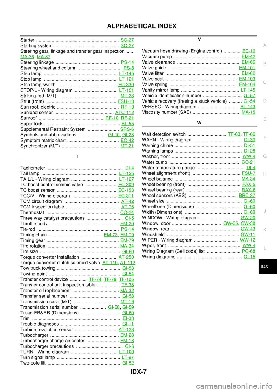
Wheel size ..........................................................GI-60
Wheelbase (Dimensions) ....................................GI-60
Width (Dimensions) ............................................GI-60
WINDOW - Wiring diagram ...............................GW-20
Window, door ......................................GW-35,GW-38
Window, rear .....................................................GW-43
Windshield ........................................................GW-11
WIPER - Wiring diagram ..................................WW-12
Wiper, front ........................................................WW-4
Wiring Diagram (Cell code) list ..........................PG-68
Wiring diagrams ..................................................GI-15
Page 2816 of 3171
SERVICE DATA AND SPECIFICATIONS (SDS)
RSU-11
C
D
F
G
H
I
J
K
L
MA
B
RSU
SERVICE DATA AND SPECIFICATIONS (SDS)PFP:00030
General Specifications (Rear)EES002JK
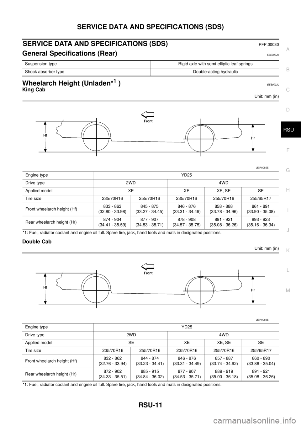
Wheelarch Height (Unladen*1)EES002JL
King Cab
Unit: mm (in)
*1: Fuel, radiator coolant and engine oil full. Spare tire, jack, hand tools and mats in designated positions.
Double Cab
Unit: mm (in)
*1: Fuel, radiator coolant and engine oil full. Spare tire, jack, hand tools and mats in designated positions.Suspension type Rigid axle with semi-elliptic leaf springs
Shock absorber type Double-acting hydraulic
Engine type YD25
Drive type 2WD 4WD
Applied model XE XE XE, SE SE
Tire size 235/70R16 255/70R16 235/70R16 255/70R16 255/65R17
Front wheelarch height (Hf)833 - 863
(32.80 - 33.98)845 - 875
(33.27 - 34.45)846 - 876
(33.31 - 34.49)858 - 888
(33.78 - 34.96)861 - 891
(33.90 - 35.08)
Rear wheelarch height (Hr)874 - 904
(34.41 - 35.59)877 - 907
(34.53 - 35.71)878 - 908
(34.57 - 35.75)891 - 921
(35.08 - 36.26)893 - 923
(35.16 - 36.34)
LEIA0085E
Engine type YD25
Drive type 2WD 4WD
Applied model SE XE XE, SE SE
Tire size 235/70R16 255/70R16 235/70R16 255/70R16 255/65R17
Front wheelarch height (Hf)832 - 862
(32.76 - 33.94)844 - 874
(33.23 - 34.41)846 - 876
(33.31 - 34.49)857 - 887
(33.74 - 34.92)860 - 890
(33.86 - 35.04)
Rear wheelarch height (Hr)872 - 902
(34.33 - 35.51)885 - 915
(34.84 - 36.02)877 - 907
(34.53 - 35.71)889 - 919
(35.00 - 36.18)891 - 921
(35.08 - 36.26)
LEIA0085E
Page 3005 of 3171
TF-38
TROUBLE DIAGNOSIS
Trouble Diagnosis Chart for Symptoms
EDS0031U
If 4WD warning lamp turns ON, perform self-diagnosis. Refer toTF-49, "Self-Diagnostic Procedure".
Transfer Control Unit Input/Output Signal Reference ValuesEDS0031V
TRANSFER CONTROL UNIT INSPECTION TABLE
Specifications with CONSULT-II
Symptom Condition Check item Reference page
4WD shift indicator lamp and 4LO indicator
lamp do not turn ON
(4WD shift indicator lamp and 4LO indicator
lamp check)Ignition switch: ONPower supply and ground for transfer
control unit
TF-88
Transfer shut off relay
Combination meter
4WD warning lamp does not turn ON
(4WD warning lamp check)Ignition switch: ONPower supply and ground for transfer
control unit
TF-91
Transfer shut off relay
Combination meter
4WD shift indicator lamp or 4LO indicator
lamp does not changeEngine running4WD shift switch
TF-94
Wait detection switch
4LO switch
AT P s w i t c h
Transfer inner parts
ATP warning lamp does not turn ON Engine runningCAN communication line
TF-96
4WD shift switch
PNP switch signal
AT P s w i t c h
Combination meter
Transfer inner parts
4WD shift indicator lamp repeats flashing Engine runningWait detection switch
TF-98
4LO switch
Transfer inner parts
4WD warning lamp flashes slowly
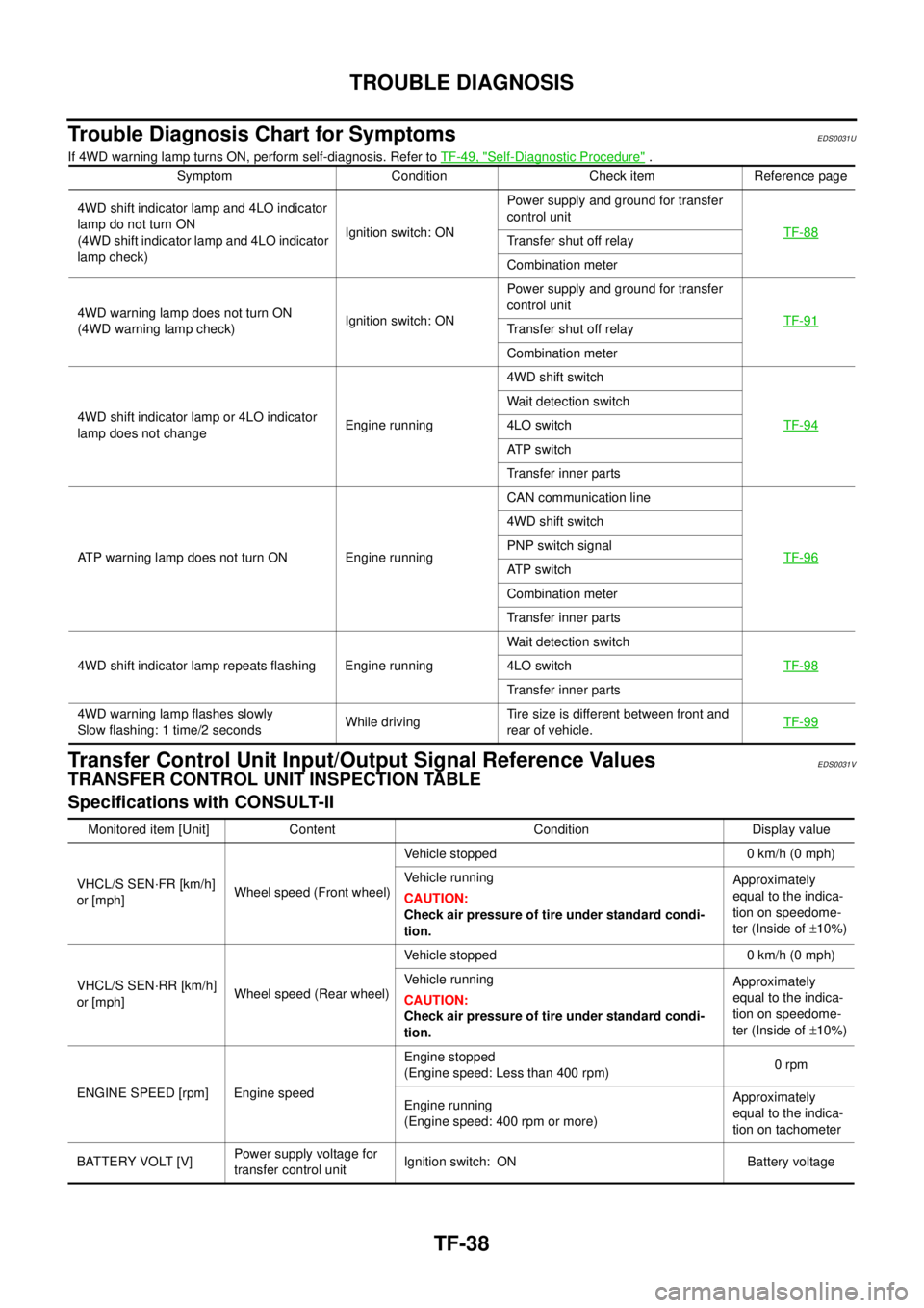
Slow flashing: 1 time/2 secondsWhile drivingTire size is different between front and
rear of vehicle.TF-99
Monitored item [Unit] Content Condition Display value
VHCL/S SEN·FR [km/h]
or [mph]Wheel speed (Front wheel)Vehicle stopped 0 km/h (0 mph)
Vehicle running
CAUTION:
Check air pressure of tire under standard condi-
tion.Approximately
equal to the indica-
tion on speedome-
ter (Inside of±10%)
VHCL/S SEN·RR [km/h]
or [mph]Wheel speed (Rear wheel)Vehicle stopped 0 km/h (0 mph)
Vehicle running
CAUTION:
Check air pressure of tire under standard condi-
tion.Approximately
equal to the indica-
tion on speedome-
ter (Inside of±10%)
ENGINE SPEED [rpm] Engine speedEngine stopped
(Engine speed: Less than 400 rpm)0rpm
Engine running
(Engine speed: 400 rpm or more)Approximately
equal to the indica-
tion on tachometer
BATTERY VOLT [V]Power supply voltage for
transfer control unitIgnition switch: ON Battery voltage
Page 3107 of 3171
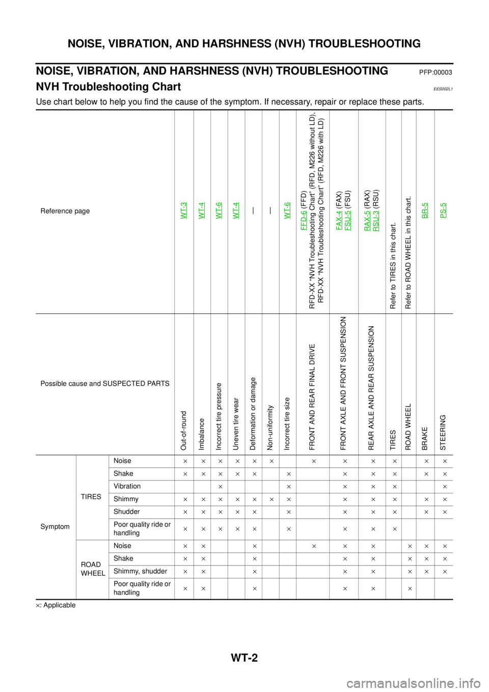
WT-2
NOISE, VIBRATION, AND HARSHNESS (NVH) TROUBLESHOOTING
NOISE, VIBRATION, AND HARSHNESS (NVH) TROUBLESHOOTING
PFP:00003
NVH Troubleshooting ChartEES002L1
Use chart below to help you find the cause of the symptom. If necessary, repair or replace these parts.
´: ApplicableReference page
WT-3WT-4WT-6WT-4—
—
WT-6
FFD-6
(FFD)
RFD-XX “NVH Troubleshooting Chart” (RFD, M226 without LD),
RFD-XX “NVH Troubleshooting Chart” (RFD, M226 with LD)
FAX-4(FAX)
FSU-5(FSU)
RAX-5(RAX)
RSU-3(RSU)
Refer to TIRES in this chart.
Refer to ROAD WHEEL in this chart.
BR-5
PS-5
Possible cause and SUSPECTED PARTS
Out-of-round
Imbalance
Incorrect tire pressure
Uneven tire wear
Deformation or damage
Non-uniformity
Incorrect tire size
FRONT AND REAR FINAL DRIVE
FRONT AXLE AND FRONT SUSPENSION
REAR AXLE AND REAR SUSPENSION
TIRES
ROAD WHEEL
BRAKE
STEERING
SymptomTIRESNoise´ ´´´´´ ´ ´ ´ ´ ´ ´
Shake´´´´´ ´ ´ ´ ´ ´´
Vibration´´´´´´
Shimmy´ ´´´´´´ ´ ´ ´ ´ ´
Shudder´´´´´ ´ ´ ´ ´ ´´
Poor quality ride or
handling´´´´´ ´ ´ ´ ´
ROAD
WHEELNoise´´ ´ ´ ´ ´ ´´´
Shake´´ ´ ´ ´ ´´´
Shimmy, shudder´´ ´ ´ ´ ´´´
Poor quality ride or
handling´´ ´ ´ ´ ´
Page 3111 of 3171

WT-6
SERVICE DATA AND SPECIFICATIONS (SDS)
SERVICE DATA AND SPECIFICATIONS (SDS)
PFP:00030
Road WheelEES002L5
TireEES002L6
Unit: kPa (kg/cm2, psi) Wheel type AluminumSteel
Inside Outside
Maximum radial
runout limitLateral mm (in) 0.3 (0.012) or less 1.0 (0.039) or less 0.9 (0.035) or less
Radial mm (in) 0.3 (0.012) or less 0.8 (0.031) or less 0.4 (0.016) or less
Maximum residual
imbalanceDynamic
(at rim flange)Less than 5 g (0.18 oz) (per side)
Static (at rim flange) Less than 10 g (0.35 oz)
Tire sizeAir pressure
Conventional tire Spare tire
Full size spare tire — 240 (2.4, 35)
235/70R16 240 (2.4, 35) —
255/70R16 240 (2.4, 35) —
265/70R16 240 (2.4, 35) —
255/65R17 240 (2.4, 35) —